laboratory “freak wave” generation for the study of extreme ... - FZK
laboratory “freak wave” generation for the study of extreme ... - FZK
laboratory “freak wave” generation for the study of extreme ... - FZK

You also want an ePaper? Increase the reach of your titles
YUMPU automatically turns print PDFs into web optimized ePapers that Google loves.
cylinder in <strong>the</strong> wave flume (Clauss and Bergmann, 1986; Clauss and Kühnlein,<br />
1997).<br />
Concerning <strong>extreme</strong> wave loadings <strong>of</strong> a structure or <strong>of</strong> a structural component<br />
it is <strong>of</strong> particular interest to analyse single wave effects in a wave flume. Single wave<br />
tests have <strong>the</strong> advantage that very high sampling rates <strong>for</strong> <strong>the</strong> data acquisition can be<br />
used. In <strong>the</strong> present <strong>study</strong>, pressure impact time histories were resolved in <strong>the</strong> range<br />
<strong>of</strong> milliseconds and below. Local loads or pressures were determined exactly and<br />
total <strong>for</strong>ces as well as wave kinematics were measured simultaneously (Wienke et<br />
al., 2000).<br />
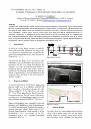
TEST SET-UP<br />
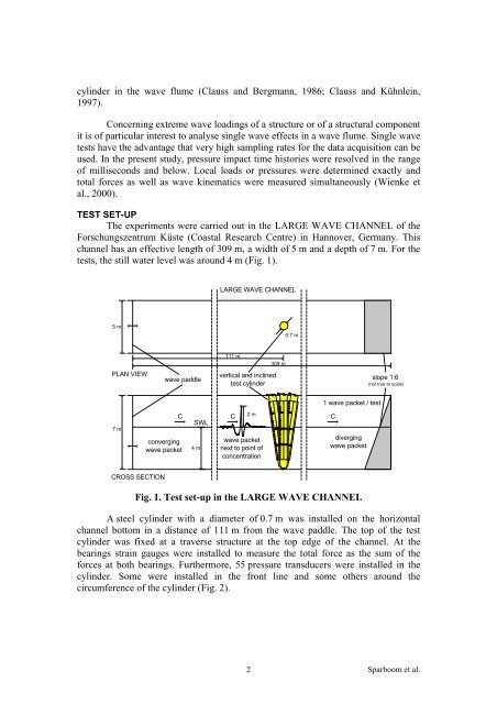
The experiments were carried out in <strong>the</strong> LARGE WAVE CHANNEL <strong>of</strong> <strong>the</strong><br />
Forschungszentrum Küste (Coastal Research Centre) in Hannover, Germany. This<br />
channel has an effective length <strong>of</strong> 309 m, a width <strong>of</strong> 5 m and a depth <strong>of</strong> 7 m. For <strong>the</strong><br />
tests, <strong>the</strong> still water level was around 4 m (Fig. 1).<br />
5 m<br />
PLAN VIEW<br />
7 m<br />
converging<br />
wave packet<br />
CROSS SECTION<br />
wave paddle<br />
C C 2 m<br />
C<br />
SWL<br />
4 m<br />
LARGE WAVE CHANNEL<br />
111 m<br />
vertical and inclined<br />
test cylinder<br />
wave packet<br />
next to point <strong>of</strong><br />
concentration<br />
Fig. 1. Test set-up in <strong>the</strong> LARGE WAVE CHANNEL<br />
A steel cylinder with a diameter <strong>of</strong> 0.7 m was installed on <strong>the</strong> horizontal<br />
channel bottom in a distance <strong>of</strong> 111 m from <strong>the</strong> wave paddle. The top <strong>of</strong> <strong>the</strong> test<br />
cylinder was fixed at a traverse structure at <strong>the</strong> top edge <strong>of</strong> <strong>the</strong> channel. At <strong>the</strong><br />
bearings strain gauges were installed to measure <strong>the</strong> total <strong>for</strong>ce as <strong>the</strong> sum <strong>of</strong> <strong>the</strong><br />
<strong>for</strong>ces at both bearings. Fur<strong>the</strong>rmore, 55 pressure transducers were installed in <strong>the</strong><br />
cylinder. Some were installed in <strong>the</strong> front line and some o<strong>the</strong>rs around <strong>the</strong><br />
circumference <strong>of</strong> <strong>the</strong> cylinder (Fig. 2).<br />
2<br />
309 m<br />
0.7 m<br />
1 wave packet / test<br />
diverging<br />
wave packet<br />
slope 1:6<br />
(not true to scale)<br />
Sparboom et al.