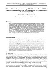
laboratory “freak wave” generation for the study of extreme ... - FZK
laboratory “freak wave” generation for the study of extreme ... - FZK
laboratory “freak wave” generation for the study of extreme ... - FZK

Create successful ePaper yourself
Turn your PDF publications into a flip-book with our unique Google optimized e-Paper software.
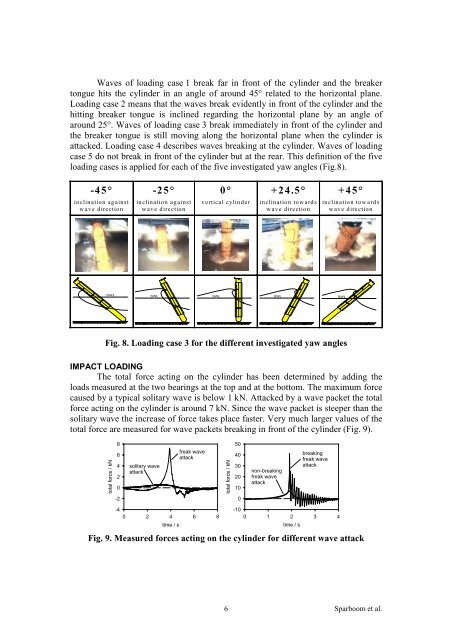
Waves <strong>of</strong> loading case 1 break far in front <strong>of</strong> <strong>the</strong> cylinder and <strong>the</strong> breaker<br />
tongue hits <strong>the</strong> cylinder in an angle <strong>of</strong> around 45° related to <strong>the</strong> horizontal plane.<br />
Loading case 2 means that <strong>the</strong> waves break evidently in front <strong>of</strong> <strong>the</strong> cylinder and <strong>the</strong><br />
hitting breaker tongue is inclined regarding <strong>the</strong> horizontal plane by an angle <strong>of</strong><br />
around 25°. Waves <strong>of</strong> loading case 3 break immediately in front <strong>of</strong> <strong>the</strong> cylinder and<br />
<strong>the</strong> breaker tongue is still moving along <strong>the</strong> horizontal plane when <strong>the</strong> cylinder is<br />
attacked. Loading case 4 describes waves breaking at <strong>the</strong> cylinder. Waves <strong>of</strong> loading<br />
case 5 do not break in front <strong>of</strong> <strong>the</strong> cylinder but at <strong>the</strong> rear. This definition <strong>of</strong> <strong>the</strong> five<br />
loading cases is applied <strong>for</strong> each <strong>of</strong> <strong>the</strong> five investigated yaw angles (Fig.8).<br />
-45°<br />
inclination against<br />
wave direction<br />
-25°<br />
inclination against<br />
wave direction<br />
0°<br />
vertical cylinder<br />
Fig. 8. Loading case 3 <strong>for</strong> <strong>the</strong> different investigated yaw angles<br />
IMPACT LOADING<br />
The total <strong>for</strong>ce acting on <strong>the</strong> cylinder has been determined by adding <strong>the</strong><br />
loads measured at <strong>the</strong> two bearings at <strong>the</strong> top and at <strong>the</strong> bottom. The maximum <strong>for</strong>ce<br />
caused by a typical solitary wave is below 1 kN. Attacked by a wave packet <strong>the</strong> total<br />
<strong>for</strong>ce acting on <strong>the</strong> cylinder is around 7 kN. Since <strong>the</strong> wave packet is steeper than <strong>the</strong><br />
solitary wave <strong>the</strong> increase <strong>of</strong> <strong>for</strong>ce takes place faster. Very much larger values <strong>of</strong> <strong>the</strong><br />
total <strong>for</strong>ce are measured <strong>for</strong> wave packets breaking in front <strong>of</strong> <strong>the</strong> cylinder (Fig. 9).<br />
Fig. 9. Measured <strong>for</strong>ces acting on <strong>the</strong> cylinder <strong>for</strong> different wave attack<br />
6<br />
+24.5°<br />
inclination towards<br />
wave direction<br />
SWL SWL SWL SWL SWL<br />
total <strong>for</strong>ce / kN<br />
8<br />
6<br />
4<br />
2<br />
0<br />
-2<br />
solitary wave<br />
attack<br />
freak wave<br />
attack<br />
-4<br />
0 2 4<br />
time / s<br />
6 8<br />
total <strong>for</strong>ce / kN<br />
50<br />
40<br />
30<br />
20<br />
10<br />
0<br />
non-breaking<br />
freak wave<br />
attack<br />
breaking<br />
freak wave<br />
attack<br />
-10<br />
0 1 2<br />
time / s<br />
3 4<br />
+45°<br />
inclination towards<br />
wave direction<br />
Sparboom et al.