YCW 750 OG Curtain Wall System - Florida Building Code ...
YCW 750 OG Curtain Wall System - Florida Building Code ...
YCW 750 OG Curtain Wall System - Florida Building Code ...

You also want an ePaper? Increase the reach of your titles
YUMPU automatically turns print PDFs into web optimized ePapers that Google loves.
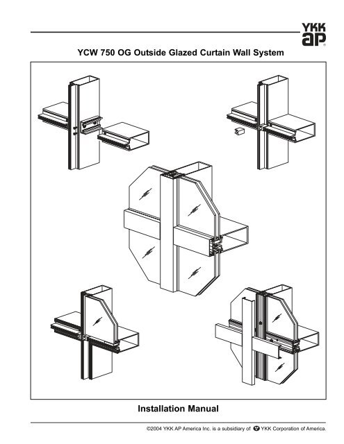
<strong>YCW</strong> <strong>750</strong> <strong>OG</strong> Outside Glazed <strong>Curtain</strong> <strong>Wall</strong> <strong>System</strong><br />
Installation Manual<br />
©2004 YKK AP America Inc. is a subsidiary of YKK Corporation of America.
<strong>YCW</strong> <strong>750</strong> <strong>OG</strong> <strong>Curtain</strong> <strong>Wall</strong> <strong>System</strong><br />
TABLE OF CONTENTS<br />
Installation Notes . . . . . . . . . . . . . . . . . . . . . . . . . . . . . . . . . . . . . . . . Page ii<br />
PARTS DESCRIPTION<br />
<strong>YCW</strong> <strong>750</strong> <strong>OG</strong> Framing Members . . . . . . . . . . . . . . . . . . . . . . . . . . . . Page 1 & 2<br />
<strong>YCW</strong> <strong>750</strong> <strong>OG</strong> Accessories . . . . . . . . . . . . . . . . . . . . . . . . . . . . . . . . . Page 3 to 5<br />
FRAME FABRICATION<br />
Anchoring Methods/Framing Types . . . . . . . . . . . . . . . . . . . . . . . . . . Page 6 & 7<br />
Fabricate Vertical Mullions . . . . . . . . . . . . . . . . . . . . . . . . . . . . . . . . . Page 8 & 9<br />
Using Alternate Reinforcing . . . . . . . . . . . . . . . . . . . . . . . . . . . . . . . . Page 10<br />
Attach Shear Blocks/Clips for Horizontals . . . . . . . . . . . . . . . . . . . . . Page 11<br />
Attach “J” Anchors . . . . . . . . . . . . . . . . . . . . . . . . . . . . . . . . . . . . . . . Page 12<br />
Fabricate Horizontal Members . . . . . . . . . . . . . . . . . . . . . . . . . . . . . . Page 13 to 15<br />
Fabricate Pressure Plates . . . . . . . . . . . . . . . . . . . . . . . . . . . . . . . . . Page 16<br />
Fabricate Face Covers . . . . . . . . . . . . . . . . . . . . . . . . . . . . . . . . . . . . Page 17<br />
FRAME INSTALLATION<br />
Typical Vertical Splice . . . . . . . . . . . . . . . . . . . . . . . . . . . . . . . . . . . . . Page 18 & 19<br />
Install Continuous Perimeter Anchor . . . . . . . . . . . . . . . . . . . . . . . . . Page 20<br />
Jamb/Vertical Installation With Perimeter Anchors . . . . . . . . . . . . . . . Page 21<br />
Jamb/Vertical Installation With Mullion End Anchors . . . . . . . . . . . . . Page 22<br />
Install Wind Load / Dead Load Anchors . . . . . . . . . . . . . . . . . . . . . . . Page 23 & 24<br />
Attach Horizontal Members . . . . . . . . . . . . . . . . . . . . . . . . . . . . . . . . Page 25 to 27<br />
Apply Perimeter Sealant . . . . . . . . . . . . . . . . . . . . . . . . . . . . . . . . . . . Page 28<br />
Install Joint Plugs . . . . . . . . . . . . . . . . . . . . . . . . . . . . . . . . . . . . . . . . Page 29<br />
GLAZING<br />
Install Glazing Adaptors . . . . . . . . . . . . . . . . . . . . . . . . . . . . . . . . . . . Page 30<br />
Install Interior Glazing Gaskets . . . . . . . . . . . . . . . . . . . . . . . . . . . . . . Page 31<br />
Install Setting & Side Blocks . . . . . . . . . . . . . . . . . . . . . . . . . . . . . . . Page 32<br />
Install Exterior Glazing Gaskets . . . . . . . . . . . . . . . . . . . . . . . . . . . . . Page 33<br />
Install Glass . . . . . . . . . . . . . . . . . . . . . . . . . . . . . . . . . . . . . . . . . . . . Page 33<br />
Pressure Plate Layout and Assembly . . . . . . . . . . . . . . . . . . . . . . . . . Page 34<br />
Install Exterior Face Covers . . . . . . . . . . . . . . . . . . . . . . . . . . . . . . . . Page 35<br />
Effective Date: July 15, 2004 Page-i
Page-ii<br />
Installation Notes<br />
<strong>YCW</strong> <strong>750</strong> <strong>OG</strong> <strong>Curtain</strong> <strong>Wall</strong> <strong>System</strong><br />
1. Do not drop, roll or drag boxes of aluminum framing. Move and stack boxes with proper support<br />
to prevent distortion. If fork lifts are used be especially careful about striking the boxes when lifting<br />
or moving.<br />
2. Store in a dry, out of the way area. If rain exposure, condensation or any water contact is likely,<br />
then all packaging material should be removed. Wet packaging materials will discolor and may stain<br />
aluminum finishes and paints.<br />
3. All materials should be checked for quality and quantity upon receipt, YKK must be notified<br />
immediately of any discrepancies in shipment. Check to make sure that you have the required shims,<br />
sealants, supplies and tools necessary for the installation.<br />
4. Carefully check the openings and surrounding conditions that will receive your material.<br />
Remember, if the construction is not per the construction documents, it is your responsibility to notify<br />
the general contractor in writing. Any discrepancies must be brought to the general contractor's<br />
attention before you proceed with the installation.<br />
5. Gather your shop drawings, materials, packing list, and this installation manual. Carefully review<br />
parts location, the sequence it goes therein, when you glaze it and how you seal it. Installation<br />
instructions are of a general nature and may not cover every condition you will encounter. The shop<br />
drawings and/or installation manuals were prepared specifically for the product.<br />
6. Any material substitutions must be of equal or greater quality.<br />
7. Make certain that material samples have been sent for compatibility testing for all manufacturer's<br />
sealants involved. Make certain sealants have been installed in strict accordance with the<br />
manufacturer's recommendations and specifications.<br />
8. Remember to isolate, in an approved manner, all aluminum from uncured masonry or other<br />
incompatible materials.<br />
9. <strong>System</strong>-to-structure fasteners are not supplied by YKK. Fasteners called out on shop drawings<br />
are to indicate minimum sizes for design loading.<br />
10. If any questions arise concerning YKK products or their installation, contact YKK AP for<br />
clarification before proceeding.<br />
11. YKK storefront and/or curtain wall framing is typically completed before drywall, flooring and<br />
other products which may still be in process. Take the extra time to wrap and protect the work that<br />
you have proudly produced, because no one else will.<br />
12. Cutting tolerances are plus zero, minus one thirty second unless otherwise noted.<br />
13. Check our website, www.ykkap.com, for the latest installation manual update prior to<br />
commencing work.<br />
Effective Date: July 15, 2004
<strong>YCW</strong> <strong>750</strong> <strong>OG</strong> <strong>Curtain</strong> <strong>Wall</strong> <strong>System</strong><br />
Vertical / Horizontal<br />
2-1/2” x 5-1/4”<br />
For 1/4” Glazing<br />
Vertical / Horizontal<br />
2-1/2” x 3-3/4”<br />
For 1/4” Glazing<br />
Horizontal<br />
Two Piece<br />
2-1/2” x 5-1/4”<br />
For 1/4” Glazing<br />
Horizontal<br />
Two Piece<br />
2-1/2” x 3-3/4”<br />
For 1/4” Glazing<br />
Vertical / Horizontal<br />
2-1/2” x 5-1/4”<br />
For 1” Glazing<br />
Vertical / Horizontal<br />
2-1/2” x 5-1/4”<br />
For 1” Glazing<br />
Vertical / Horizontal<br />
2-1/2” x 3-3/4”<br />
For 1” Glazing<br />
Vertical / Horizontal<br />
2-1/2” x 3-3/4”<br />
For 1” Glazing<br />
Vertical /<br />
Horizontal<br />
2-1/2” x 6-3/4”<br />
For 1” Glazing<br />
Horizontal<br />
Open Back<br />
2-1/2” x 5-1/4”<br />
For 1” Glazing<br />
Horizontal<br />
Open Back<br />
2-1/2” x 3-3/4”<br />
For 1” Glazing<br />
FRAMING MEMBERS<br />
E9-1246<br />
E9-1250<br />
E9-1258<br />
E9-1259<br />
E9-1215<br />
E9-1225<br />
E9-1235<br />
E9-3537<br />
E9-1242<br />
E9-1255<br />
E9-1257<br />
* Splay mullions and other face covers are available, contact YKK AP.<br />
Horizontal Cover<br />
For 5-1/4” Back Horizontals<br />
Horizontal Cover<br />
For 3-3/4” Back Horizontals<br />
Pressure Plate<br />
E9-1216 with PVC Isolator<br />
Punched 9” O.C.<br />
Perimeter Pressure Plate<br />
For 1/4” Glazing<br />
E9-3572 with PVC Isolator<br />
Punched 9” O.C.<br />
Perimeter Pressure Plate<br />
For 1” Glazing<br />
E9-3569 with PVC Isolator<br />
Punched 9” O.C.<br />
Pressure Plate<br />
For Deep Covers<br />
E9-3574 with PVC Isolator<br />
Punched 9” O.C.<br />
Perimeter Pressure Plate<br />
For Deep Covers, 1” Glazing<br />
E9-3576 with PVC Isolator<br />
Punched 9” O.C.<br />
Face Cover<br />
2-1/2 x 3/4”<br />
Face Cover<br />
2-1/2 x 1-3/4”<br />
Face Cover<br />
2-1/2” x 2-3/8”<br />
Horizontal Face Cover<br />
11/16” x 2-1/2”<br />
E9-1256<br />
E9-1038<br />
AS-1216<br />
AS-3572<br />
AS-3569<br />
AS-3574<br />
AS-3576<br />
E9-1206<br />
E9-1229<br />
E9-1219<br />
E9-1207<br />
Effective Date: July 15, 2004 Page-1
Page-2<br />
Bull Nose Face Cover<br />
2-1/2” x 2”<br />
Glazing Adaptor<br />
For 1/4” glazing<br />
Glazing Adaptor<br />
For 1/2” Glazing<br />
Flush Pocket Filler<br />
For 1” glazing<br />
Perimeter Anchor<br />
For 1/4” Glazing<br />
Perimeter Anchor<br />
For 1” Glazing<br />
Perimeter Channel<br />
For 1” Glazing<br />
90° Outside Corner<br />
Adaptor<br />
For 1/4” Glazing<br />
90° Outside Corner<br />
Adaptor<br />
For 1” Glazing<br />
90° Outside Corner<br />
Pressure Plate<br />
with PVC Isolator, punched<br />
9” O.C., For 1/4” Glazing<br />
90° Outside Corner<br />
Pressure Plate<br />
with PVC Isolator, punched<br />
9” O.C., For 1” Glazing<br />
FRAMING MEMBERS<br />
E9-1293<br />
E9-1220<br />
E9-1232<br />
E9-1253<br />
E9-1248<br />
E9-1223<br />
E9-1231<br />
E9-1236<br />
E9-1226<br />
AS-1237<br />
AS-1227<br />
<strong>YCW</strong> <strong>750</strong> <strong>OG</strong> <strong>Curtain</strong> <strong>Wall</strong> <strong>System</strong><br />
90° Outside Corner<br />
Face Cover<br />
For 1” Glazing<br />
90° Outside Corner<br />
Face Cover<br />
For 1/4” Glazing<br />
Interior Cover Base<br />
Use with E9-1281<br />
Interior Cover<br />
For 90° Outside Corner<br />
Use with E9-1280<br />
Single Acting<br />
Transom Bar<br />
Elastomer Weathering<br />
E2-0051 Included<br />
Standard Door Jamb<br />
For 1/4” Glazing<br />
Use with AS-0417<br />
Standard Door Jamb<br />
For 1” Glazing<br />
Use with AS-0417<br />
Heavy Duty Door Jamb<br />
Use with AS-0441<br />
Heavy Duty Door Stop<br />
Elastomer Weathering<br />
E2-0051 Included<br />
Use with E9-3531<br />
Snap-In Door Stop<br />
Elastomer Weathering<br />
E2-0051 Included<br />
Use with E9-1224<br />
E9-1228<br />
E9-1238<br />
E9-1280<br />
E9-1281<br />
AS-0402<br />
E9-1224<br />
E9-3513<br />
E9-3531<br />
AS-0441<br />
AS-0417<br />
Effective Date: July 15, 2004
<strong>YCW</strong> <strong>750</strong> <strong>OG</strong> <strong>Curtain</strong> <strong>Wall</strong> <strong>System</strong><br />
Standard Shear Block<br />
For E9-1235, E9-1250,<br />
& E9-3537, 3.125” Long<br />
Standard Shear Block<br />
For E9-1215, E9-1225,<br />
E9-1246, 4.375” Long<br />
Standard Shear Block<br />
For E9-1242, 6.000” Long<br />
“J” Anchor<br />
For E9-1235, E9-1250,<br />
& E9-3537, 3.125” Long<br />
“J” Anchor<br />
For E9-1215, E9-1225,<br />
E9-1246, 4.375” Long<br />
“J” Anchor<br />
For E9-1242, 6.000” Long<br />
Shear Block (For E-Slot)<br />
For E9-1235, E9-1250,<br />
& E9-3537, 3.125” Long<br />
Shear Block (For E-Slot)<br />
For E9-1215, E9-1225,<br />
E9-1246, 4.375” Long<br />
Shear Block (For E-Slot)<br />
For E9-1242, 6.000” Long<br />
Shear Clip<br />
For E9-1257 & E9-1259<br />
2.736” Long<br />
Shear Clip<br />
For E9-1255 & E9-1258<br />
3.986” Long<br />
ACCESSORIES<br />
E1-3503<br />
E1-3504<br />
E1-3506<br />
E1-3501<br />
E1-3502<br />
E1-3505<br />
E1-1206<br />
E1-1200<br />
E1-1236<br />
E1-1214<br />
E1-1213<br />
Shear Block for 90°<br />
Outside Corner<br />
For E9-1235, E9-1250,<br />
& E9-3537, 5.794” Long<br />
Shear Block for 90°<br />
Outside Corner<br />
For E9-1215, E9-1225,<br />
E9-1246, 7.562” Long<br />
Shear Block for 90°<br />
Outside Corner<br />
For E9-1242<br />
9.860” Long<br />
Shear Clip for 90°<br />
Outside Corner<br />
For E9-1255 & E9-1258<br />
7.135” Long<br />
Shear Clip for 90°<br />
Outside Corner<br />
For E9-1257 & E9-1259<br />
5.369” Long<br />
“J” Anchor for 90°<br />
Outside Corner (RH)<br />
For E9-1235, E9-1250,<br />
& E9-3537, 5.669” Long<br />
“J” Anchor for 90°<br />
Outside Corner (LH)<br />
For E9-1235, E9-1250,<br />
& E9-3537, 5.669” Long<br />
“J” Anchor for 90°<br />
Outside Corner (RH)<br />
For E9-1215, E9-1225,<br />
E9-1246, 7.437” Long<br />
“J” Anchor for 90°<br />
Outside Corner (LH)<br />
For E9-1215, E9-1225,<br />
E9-1246, 7.437” Long<br />
“J” Anchor for 90°<br />
Outside Cor. (RH)<br />
For E9-1242<br />
9.735” Long<br />
“J” Anchor for 90°<br />
Outside Cor. (LH)<br />
For E9-1242<br />
9.735” Long<br />
Mullion Splice Sleeve<br />
For E9-1235, E9-1250<br />
& E9-3537<br />
E1-3503A<br />
E1-3504A<br />
E1-3506A<br />
E1-1213A<br />
E1-1213B<br />
E1-1214A<br />
E1-1214B<br />
E1-3501A<br />
E1-3501B<br />
E1-3502A<br />
E1-3502B<br />
E1-3505A<br />
E1-3505B<br />
E1-1212<br />
Effective Date: July 15, 2004 Page-3
Page-4<br />
Mullion Splice Sleeve<br />
For E9-1215, E9-1225<br />
& E9-1246<br />
Mullion Splice Sleeve<br />
For E9-1242<br />
Mullion “T” Anchor<br />
For E9-1235, E9-1250,<br />
& E9-3537, 3.462” Long<br />
Mullion “T” Anchor<br />
For E9-1215<br />
4.866” Long<br />
Mullion “T” Anchor<br />
For E9-1225 & E9-1246<br />
4.960” Long<br />
Mullion “T” Anchor<br />
For E9-1242<br />
6.453” Long<br />
Mullion “F” Anchor<br />
For E9-1235, E9-1250<br />
& E9-3537, 3.462” Long<br />
Mullion “F” Anchor<br />
For E9-1215<br />
4.866” Long<br />
Mullion “F” Anchor<br />
For E9-1225 & E9-1246<br />
4.960” Long<br />
Mullion “F” Anchor<br />
For E9-1242<br />
6.453” Long<br />
Temporary Glass<br />
Retainer<br />
2” Long<br />
Mullion End Cap<br />
For Insulated Glazing<br />
2.500” x 2.313” x 0.050”<br />
ACCESSORIES<br />
E1-1201<br />
E1-1299<br />
E1-1207<br />
E1-1208<br />
E1-1209<br />
E1-1238<br />
E1-1232<br />
E1-1233<br />
E1-1231<br />
E1-1240<br />
E1-1294<br />
E1-1286<br />
<strong>YCW</strong> <strong>750</strong> <strong>OG</strong> <strong>Curtain</strong> <strong>Wall</strong> <strong>System</strong><br />
Mullion End Cap for<br />
90° Outside Corner<br />
For 1/4” Glazing<br />
Mullion End Cap for<br />
90° Outside Corner<br />
For 1” Glazing<br />
Face Cover<br />
Splice Sleeve<br />
For E9-1206<br />
Face Cover<br />
Splice Sleeve<br />
For E9-1219<br />
Wind Load Anchor<br />
Steel with Zinc Oxide Paint<br />
Refer to Shop Drawings<br />
for Anchor Dimensions<br />
Dead Load Anchor<br />
Steel with Zinc Oxide Paint<br />
Refer to Shop Drawings<br />
for Anchor Dimensions<br />
Reinforcing Steel<br />
2” x 4” x 1/4”<br />
For 5-1/4” Back Verticals<br />
Steel with Zinc Oxide Paint<br />
Steel Reinforcement<br />
2” x 4-1/2” x 1/4”<br />
For 5-1/4” Back Verticals<br />
Steel with Zinc Oxide Paint<br />
Setting Block<br />
For 1/4” Glazing<br />
EPDM with Pressure<br />
Sensitive Adhesive<br />
Side Block<br />
For 1/4” Glazing<br />
EPDM with Pressure<br />
Sensitive Adhesive<br />
Setting Block<br />
For 1” Glazing<br />
EPDM with Pressure<br />
Sensitive Adhesive<br />
Side Block<br />
For 1” Glazing<br />
EPDM with Pressure<br />
Sensitive Adhesive<br />
E1-3519<br />
E1-3520<br />
E1-1202<br />
E1-1203<br />
E1-1204*<br />
Project<br />
Specific<br />
E1-1205*<br />
Project<br />
Specific<br />
E1-0162<br />
E1-0154<br />
E2-0112<br />
E2-0113<br />
E2-0104<br />
E2-0105<br />
Effective Date: July 15, 2004
<strong>YCW</strong> <strong>750</strong> <strong>OG</strong> <strong>Curtain</strong> <strong>Wall</strong> <strong>System</strong><br />
End Dam Plug<br />
Use with E9-1223 &<br />
E9-1231<br />
Standard Joint Plug<br />
For 1/4” Glazing<br />
EPDM Sponge<br />
Standard Joint Plug<br />
For 1” Glazing<br />
EPDM Sponge<br />
Joint Plug<br />
For slide in mullion<br />
at end bays, 1/4” glazing<br />
Use with E2-0123<br />
Joint Plug<br />
For slide in mullion<br />
at end bays, 1” glazing<br />
Use with E2-0123<br />
E-Slot Plug<br />
For slide in mullion<br />
at end bays<br />
Isolator Tape<br />
1/8” x 7/16”<br />
Use with Perimeter<br />
Pressure Plate<br />
Anchor Slip Pad<br />
For Dead Load<br />
& Wind Load Anchors<br />
Interior/Exterior<br />
Glazing Gasket<br />
#8 x 3/8” PHSMS<br />
For Attachment of<br />
Glazing Adaptors<br />
#8 x 1/2” FHSMS<br />
Type AB, Undercut<br />
For Attachment of Face<br />
Cover Splice Sleeve<br />
ACCESSORIES<br />
E2-0505<br />
E2-0125<br />
E2-0102<br />
E2-0129<br />
E2-0124<br />
E2-0123<br />
E2-0239<br />
E3-0103<br />
E2-0120<br />
PC-0806<br />
FC-0808<br />
#12 x 3/4” FHSMS<br />
Type AB, Exposed Fasteners<br />
For Attachment of<br />
Horizontal to Shear Block<br />
#12 x 1-1/4” FHSMS<br />
Type AB, Concealed Fasten.<br />
For Attachment of<br />
Horizontal to Shear Block<br />
#14 x 5/8” FHSMS<br />
Type AB<br />
For Attachment of Mullion<br />
End Cap E1-1286<br />
1/4” – 20 x 5/8” HWHS<br />
Type F<br />
For Attachment of<br />
Shear Block to Vertical<br />
1/4” – 20 x 1” HWHS<br />
Type F, For Attachment of<br />
Shear Block to Vertical<br />
with Steel Reinforcing<br />
1/4” – 20 x 1” HWHMS<br />
For Attachment of<br />
Pressure Plate to Mullion<br />
& “J” Anchor at Jamb<br />
1/4”-20 x 3-1/2” HWHMS<br />
For Attachment of “J” Anchor<br />
at Intermediate Vertical<br />
1/4”-20 Nut HHMS<br />
For Attachment of “J” Anchor<br />
at Intermediate Vertical<br />
& Jamb<br />
1/4” Flat Washer<br />
For Attachment of “J” Anchor<br />
at Intermediate Vertical<br />
& Jamb<br />
1/4” Lock Washer<br />
For Attachment of “J” Anchor<br />
at Intermediate Vertical<br />
& Jamb<br />
FC-1212<br />
FC-1220<br />
FC-1410<br />
HF-2510<br />
HF-2516<br />
HM-2516<br />
HM-2556<br />
HM-2500<br />
WW-2500<br />
WS-2500<br />
Effective Date: July 15, 2004 Page-5
FRAME TYPES / ANCHORING METHODS<br />
The following is a guideline for common<br />
types of frames. Refer to shop drawings for<br />
exact layout of frames.<br />
Page-6<br />
FRAME FABRICATION<br />
<strong>YCW</strong> <strong>750</strong> <strong>OG</strong> <strong>Curtain</strong> <strong>Wall</strong> <strong>System</strong><br />
Smaller units may be assembled on the<br />
ground and tipped in place. Larger units<br />
require being stick assembled in place.<br />
Note: If YKK does not prepare the shop<br />
drawings for the project, a qualified engineer<br />
must approve all anchors, their arrangement,<br />
and mullion selection.<br />
All anchors must be attached to structurally<br />
sound material that will accommodate the<br />
anchor reactions.<br />
* Vertical end attachment will be continuous<br />
perimeter anchor, “J” anchor, or mullion<br />
end anchor.<br />
Fabrication of <strong>YCW</strong> <strong>750</strong> <strong>OG</strong> varies depending on the type of vertical end attachment<br />
required for a given project:<br />
Perimeter Anchors are for low load anchoring conditions (maximum 500lb. end load reaction):<br />
E9-1248, E9-1223, & E9-1231<br />
“J” Anchors are for medium to high load conditions: E1-3501, E1-3502, & E1-3505.<br />
Mullion End Anchors “F” & “T” are for high load conditions: E1-1207, E1-1208, E1-1209,<br />
E1-1231, E1-1232, E1-1233, E1-1238, & E1-1240<br />
Effective Date: July 15, 2004
<strong>YCW</strong> <strong>750</strong> <strong>OG</strong> <strong>Curtain</strong> <strong>Wall</strong> <strong>System</strong><br />
FRAME TYPES / ANCHORING METHODS<br />
Using Perimeter Anchors:<br />
FRAME FABRICATION<br />
-Vertical mullions must be notched as shown in Detail 1 on Page-8.<br />
Using Mullion End Anchors:<br />
<strong>YCW</strong> <strong>750</strong> <strong>OG</strong> has three possible end<br />
anchoring conditions: “J”, “T”, and “F”.<br />
-”J” anchors are used with jambs and<br />
intermediate verticals at the sill only.<br />
-”T” anchors are used with intermediate<br />
verticals at the head and sill.<br />
-”F” anchors are used with jamb mullions<br />
at the head and sill.<br />
-Anchor usage depends on end reaction,<br />
stress, and attachment.<br />
Mullions should be pre-assembled with<br />
shear blocks/clips, end anchors, and steel<br />
or aluminum reinforcing if necessary.<br />
Framing Members for Stick Build:<br />
-Head and sill members must be notched<br />
as shown Detail 9 on Page-14 to clear the<br />
mullion end anchors.<br />
-Closed horizontal members are used at all<br />
intermediate locations except at end bays.<br />
-Open back intermediate horizontals are<br />
used at end bays to clear the shear clips.<br />
Note: When using stick build construction,<br />
check overall frame width every<br />
fifth mullion as the wall is installed<br />
to prevent the buildup of cumulative<br />
tolerance errors.<br />
Effective Date: July 15, 2004 Page-7
FABRICATE VERTICAL MULLIONS<br />
Page-8<br />
Detail 1<br />
<strong>YCW</strong> <strong>750</strong> <strong>OG</strong> <strong>Curtain</strong> <strong>Wall</strong> <strong>System</strong><br />
FRAME FABRICATION<br />
Step 1<br />
-Cut all vertical and jamb mullions to dimensions as shown on shop drawings.<br />
Allow for 1/2” caulk joint around the frame & 1/2” joint at vertical splices.<br />
Step 2<br />
-If you are using continuous perimeter anchors, E9-1223 or E9-1248, the top and bottom of<br />
vertical and jamb mullions must be notched as shown in Detail 1.<br />
Note: Do not notch verticals when using mullion end anchors: “J”, “T”, or “F”.<br />
Effective Date: July 15, 2004
<strong>YCW</strong> <strong>750</strong> <strong>OG</strong> <strong>Curtain</strong> <strong>Wall</strong> <strong>System</strong><br />
STEP 3<br />
FABRICATE VERTICAL MULLIONS<br />
FRAME FABRICATION<br />
-Mullion hole locations for shear blocks, shear clips, and “J” anchors are shown below.<br />
-Drill 0.213” dia. (#3 drill bit) holes for shear block/clip attachment at the locations indicated.<br />
Drill 0.281” dia. (#9/32 drill bit) holes for “J” anchor attachment at the sill.<br />
See Detail 2.<br />
Note: Hole locations for shear clips, E1-1213 & E1-1214, are not the same as for<br />
shear blocks and “J” anchors.<br />
Detail 2<br />
Effective Date: July 15, 2004 Page-9
STEP 4<br />
USING ALTERNATE REINFORCING<br />
Page-10<br />
FRAME FABRICATION<br />
<strong>YCW</strong> <strong>750</strong> <strong>OG</strong> <strong>Curtain</strong> <strong>Wall</strong> <strong>System</strong><br />
If your engineering calculations require the vertical mullions to be reinforced with either<br />
steel or aluminum, secure the reinforcing to the vertical using the appropriate fasteners.<br />
-Start 3” from both ends of the mullion and install a<br />
fastener on both sides of the mullion tongue.<br />
-Stagger the fasteners on either side of the tongue<br />
going up the vertical.<br />
-Seal all screw heads with sealant.<br />
Note: Exact size of reinforcing, size and location of<br />
fasteners to be determined by a qualified engineer.<br />
Optional reinforcing is also attached on the sides of the<br />
mullion with the attachment of shear blocks.<br />
-Drill 0.281” dia. (9/32 bit) clear holes in the mullion only.<br />
-Match drill 0.213 dia. (#3 bit) tap holes in the reinforcing only.<br />
-Attach the shear blocks with HF-2516 fasteners.<br />
See Detail 3.<br />
Detail 3<br />
Effective Date: July 15, 2004
<strong>YCW</strong> <strong>750</strong> <strong>OG</strong> <strong>Curtain</strong> <strong>Wall</strong> <strong>System</strong><br />
FRAME FABRICATION<br />
STEP 5<br />
ATTACH SHEAR BLOCKS/CLIPS FOR HORIZONTALS<br />
Shear blocks are used to attach one piece horizontal members to the jamb and vertical mullions:<br />
E1-3503 for 3-3/4” back members.<br />
E1-3504 for 5-1/4” back members.<br />
E1-3506 for 6-3/4” back members.<br />
Shear clips are used to attach two piece intermediate horizontal members to the jamb and<br />
vertical mullions:<br />
E1-1213 for 5-1/4” back members.<br />
E1-1214 for 3-3/4” back members.<br />
-Attach the shear blocks/clips to jambs and verticals with two HF-2510 fasteners per block.<br />
See Detail 4.<br />
Note: See Step 4 on the previous page when using alternate reinforcing.<br />
Detail 4<br />
Effective Date: July 15, 2004 Page-11
STEP 6<br />
ATTACH “J” ANCHORS<br />
Page-12<br />
FRAME FABRICATION<br />
<strong>YCW</strong> <strong>750</strong> <strong>OG</strong> <strong>Curtain</strong> <strong>Wall</strong> <strong>System</strong><br />
In addition to anchoring the curtain wall frame to the structure, “J” anchors are used to attach<br />
sill members to jamb and vertical mullions:<br />
E1-3501 for 3-3/4” back members.<br />
E1-3502 for 5-1/4” back members.<br />
E1-3505 for 6-3/4” back members.<br />
Note: “J” anchors are used at the sill only.<br />
Attach “J” anchors at jambs:<br />
-Align the “J” anchor with the mullion and insert the HM-2516 bolts through the inside<br />
of the mullion and out the “J” anchor.<br />
-Install 1/4” flat and lock washers between the anchor and HM-2500 hex nuts.<br />
Attach “J” anchors at intermediate verticals:<br />
-Align the “J” anchors and insert the HM-2556 bolts through both anchors and the mullion.<br />
-Install 1/4” flat and lock washers between the anchor and HM-2500 hex nuts.<br />
See Detail 5.<br />
Detail 5<br />
Effective Date: July 15, 2004
<strong>YCW</strong> <strong>750</strong> <strong>OG</strong> <strong>Curtain</strong> <strong>Wall</strong> <strong>System</strong><br />
STEP 7<br />
FABRICATE HORIZONTAL MEMBERS<br />
FRAME FABRICATION<br />
-Cut all horizontal members to the daylight opening as shown in shop drawings.<br />
-Horizontal members must be fabricated as shown below to attach to shear blocks or clips.<br />
Horizontals with Exposed Fasteners:<br />
-Layout hole locations on the top of the horizontal at both ends as shown below.<br />
-Drill 0.236” diameter (#B bit) holes and countersink for #12 flat head fasteners.<br />
See Detail 6.<br />
Horizontals with Concealed Fasteners:<br />
-Layout hole locations on the face of the horizontal at both ends as shown below.<br />
-Drill 0.236” diameter (#B bit) holes and countersink for #12 flat head fasteners.<br />
See Detail 7.<br />
Detail 7<br />
Detail 6<br />
Effective Date: July 15, 2004 Page-13
STEP 7 (Continued)<br />
FABRICATE HORIZONTAL MEMBERS<br />
Two Piece Horizontals:<br />
Page-14<br />
FRAME FABRICATION<br />
<strong>YCW</strong> <strong>750</strong> <strong>OG</strong> <strong>Curtain</strong> <strong>Wall</strong> <strong>System</strong><br />
-Layout hole locations on the bottom of the horizontal along the “V”-grooves at both ends.<br />
-Drill 0.213” diameter (#3 bit) holes at each location.<br />
Be careful not to penetrate the outer wall of the mullion.<br />
See Detail 8.<br />
Detail 8<br />
If Mullion End Anchors Are Used<br />
Head and Sill Members Require Additional Fabrication:<br />
-Head and sill members must be notched out at each end to clear mullion end anchors<br />
and anchor bolts.<br />
-See Detail 9 below for notch dimensions.<br />
Detail 9<br />
Effective Date: July 15, 2004
<strong>YCW</strong> <strong>750</strong> <strong>OG</strong> <strong>Curtain</strong> <strong>Wall</strong> <strong>System</strong><br />
STEP 7 (Continued)<br />
FABRICATE HORIZONTAL MEMBERS<br />
One Piece Horizontals at End Bays (E-SLOT):<br />
FRAME FABRICATION<br />
When using one piece horizontals at end bays, horizontals must slide in from the interior.<br />
In order to clear the shear blocks on the verticals:<br />
-Notch the face and tongue of the horizontal at both ends as shown below.<br />
See Detail 10.<br />
Detail 10<br />
Effective Date: July 15, 2004 Page-15
STEP 8<br />
FABRICATE PRESSURE PLATES<br />
Horizontal Pressure Plates:<br />
Page-16<br />
FRAME FABRICATION<br />
<strong>YCW</strong> <strong>750</strong> <strong>OG</strong> <strong>Curtain</strong> <strong>Wall</strong> <strong>System</strong><br />
-Cut horizontal pressure plates to the daylight opening between verticals minus(–) 1/8”.<br />
-Pressure plate stock lengths have 0.281” dia. holes factory punched every 9”.<br />
After cutting, drill additional holes if required to ensure that end holes are within<br />
1-1/2” of each end.<br />
-Drill two 0.313” (5/16”) diameter weep holes 3” from each end and one at the<br />
centerline of the pressure plate.<br />
See Detail 11.<br />
Vertical Pressure Plates:<br />
Detail 11<br />
-Cut vertical and jamb pressure plates to the same length as the vertical mullions<br />
unless verticals are spliced.<br />
-If vertical mullions are spliced, cut pressure plates to accommodate for 1/2”<br />
expansion joint as shown in Step 10 on Pages 18 & 19.<br />
-Drill additional attachment holes if required to ensure that end holes are within<br />
1-1/2” of each end.<br />
Effective Date: July 15, 2004
<strong>YCW</strong> <strong>750</strong> <strong>OG</strong> <strong>Curtain</strong> <strong>Wall</strong> <strong>System</strong><br />
STEP 9<br />
FABRICATE FACE COVERS<br />
Horizontal Face Covers:<br />
FRAME FABRICATION<br />
-Cut horizontal face covers to the daylight opening between verticals minus(–) 1/16”.<br />
-Drill two 0.313” diameter weep holes at 1/3 points of cover as shown below.<br />
See Detail 12.<br />
Vertical Face Covers:<br />
Detail 12<br />
-Cut vertical face covers to the same length as the vertical mullions unless the<br />
verticals are spliced.<br />
-If vertical mullions are spliced, cut vertical covers to accommodate for the 1/2”<br />
expansion joint as shown in Step 10 on Pages 18 & 19.<br />
Effective Date: July 15, 2004 Page-17
STEP 10<br />
TYPICAL VERTICAL SPLICE<br />
Page-18<br />
FRAME INSTALLATION<br />
<strong>YCW</strong> <strong>750</strong> <strong>OG</strong> <strong>Curtain</strong> <strong>Wall</strong> <strong>System</strong><br />
Stagger Mullion, Pressure Plate, and Cover Splice Joints as Shown Below.<br />
Detail 13<br />
Effective Date: July 15, 2004
<strong>YCW</strong> <strong>750</strong> <strong>OG</strong> <strong>Curtain</strong> <strong>Wall</strong> <strong>System</strong><br />
STEP 10 (Continued)<br />
TYPICAL VERTICAL SPLICE<br />
FRAME INSTALLATION<br />
-Clean all surfaces as recommended by sealant manufacturer.<br />
-Apply bond breaker tape to the face of the splice sleeve at its midpoint (3” from top or bottom).<br />
-Lower the splice sleeve into top of lower mullion 2-3/4” and attach with two FC-1212 fasteners<br />
on both sides of the mullion. Screws should be installed 3/4” from the front and back of mullion<br />
and 1” down from the top.<br />
-When using 1” glazing mullions, stuff a small piece of backer rod 1/2” down the cavity behind<br />
mullion tongue and pump in sealant to fill the cavity.<br />
-Apply sealant to the face of splice sleeve on the upper half and carefully slide the upper mullion<br />
down onto the splice sleeve. Place a 1/2” temporary shim between the mullions to locate them.<br />
-Secure the upper mullion to the mid anchors and remove the temporary shims.<br />
-Apply and tool sealant to the face and sides of the splice sleeve to<br />
create a water tight joint.<br />
-Leave a 1/2” expansion joint between vertical pressure<br />
plate splices and fill the joint with sealant.<br />
-Locate pressure plate fasteners<br />
1-1/2” from each end of pressure<br />
plate splice as shown.<br />
-Apply bond breaker tape to the face<br />
of the cover splice sleeve and attach<br />
it to the lower face cover with a<br />
FC-0808 fastener on each side.<br />
-Prior to snapping on the upper<br />
portion of the face cover, apply<br />
sealant to the face of the splice.<br />
-Leave a 1/2” expansion joint<br />
between face cover splices.<br />
See Details 13 & 14.<br />
Note: Face covers, pressure<br />
plates, and mullions are<br />
staggered at splice locations.<br />
Detail 14<br />
Effective Date: July 15, 2004 Page-19
STEP 11<br />
INSTALL CONTINUOUS PERIMETER ANCHOR<br />
Page-20<br />
Detail 15<br />
<strong>YCW</strong> <strong>750</strong> <strong>OG</strong> <strong>Curtain</strong> <strong>Wall</strong> <strong>System</strong><br />
FRAME INSTALLATION<br />
-Cut perimeter anchors to size:<br />
Head and sill anchors stop 1/8” short of the structure.<br />
Vertical jamb anchors butt in between head and sill anchors.<br />
-Prepare structure for anchor attachment.<br />
-Install perimeter anchors with appropriate perimeter fasteners. Refer to shop drawings or<br />
engineering calculations for type and spacing of fasteners. Shim as required to install anchors level.<br />
-When splicing head and sill pieces together, leave 3/8” joint for expansion and install end plug,<br />
E2-0505, that has been buttered with sealant on the front, back, and bottom at the joint.<br />
-Run continuous sealant along the perimeter between the anchors and the substrate.<br />
-Seal corners of butted perimeter anchors watertight with sealant.<br />
-Butter E2-0505 end plug with butyl on all sides that touch the anchors. Then push end plug into<br />
place and tool excess sealant that comes through the cracks.<br />
-Field drill 0.313” diameter weep holes in perimeter anchor (exterior face only) at sill 3” from<br />
center line of vertical on each side.<br />
See Detail 15.<br />
Effective Date: July 15, 2004
<strong>YCW</strong> <strong>750</strong> <strong>OG</strong> <strong>Curtain</strong> <strong>Wall</strong> <strong>System</strong><br />
STEP 12<br />
JAMB/VERTICAL INSTALLATION<br />
WITH PERIMETER ANCHORS<br />
FRAME INSTALLATION<br />
-The notched ends of vertical mullions for 1” glazing leaves the interior of the mullion exposed<br />
and must be plugged prior to installation.<br />
-Install a small piece of backer rod into the notched out space directly behind the tongue<br />
at the top and bottom of the vertical mullions.<br />
-Push the backer rod into the opening at the face of the mullion.<br />
-Apply and tool sealant to seal off the opening made by the notch.<br />
-Install interior gasket, E2-0100, to jamb mullion (jamb side only) the full length of the mullion.<br />
-Position jamb into opening as shown in Detail 16.<br />
-Seal the gap between the perimeter anchor and vertical glazing pocket(s) with sealant<br />
(one side for jambs - both sides for intermediate verticals).<br />
-Install temporary retainer clip, E1-1294, at the top and bottom of the mullion.<br />
-Repeat this step for all jamb and vertical mullions.<br />
See Detail 16.<br />
Detail 16<br />
Effective Date: July 15, 2004 Page-21
STEP 13<br />
JAMB/VERTICAL INSTALLATION<br />
WITH MULLION END ANCHORS<br />
Page-22<br />
FRAME INSTALLATION<br />
-Clean all contact surfaces as recommended by<br />
sealant manufacturer.<br />
-Apply sealant into the screw raceway and along<br />
the front edge of the mullion at each end.<br />
-Prior to erecting verticals, install mullion end<br />
caps, E1-1286, at the top and bottom of the<br />
mullions with FC-1410 fasteners.<br />
-Seal all screw heads with sealant.<br />
See Detail 17.<br />
<strong>YCW</strong> <strong>750</strong> <strong>OG</strong> <strong>Curtain</strong> <strong>Wall</strong> <strong>System</strong><br />
-Insert mullion “T” and “F” anchors into the top and bottom of the mullions before erecting<br />
them into the opening.<br />
-Erect and locate the jamb and vertical mullions and temporarily attach them to the structure.<br />
All mullions must be installed plumb and true.<br />
-Field drill holes in “T”, “F”, and “J” anchors for the appropriate anchor fasteners according to<br />
shop drawings or engineering calculations. Consult YKK if load requirements are in question.<br />
See Detail 18.<br />
Detail 18<br />
Detail 17<br />
Effective Date: July 15, 2004
<strong>YCW</strong> <strong>750</strong> <strong>OG</strong> <strong>Curtain</strong> <strong>Wall</strong> <strong>System</strong><br />
FRAME INSTALLATION<br />
STEP 14<br />
INSTALL WIND LOAD / DEAD LOAD ANCHORS<br />
-Install steel wind load and dead load anchor clips. Anchor clips are normally template or<br />
line set before mullions are hung. Outstanding leg of clip must be set at 90° to offset line.<br />
The back of the vertical mullion should set 1” from the anchoring substrate.<br />
See Detail 19.<br />
Detail 19<br />
-Install, plumb, and align vertical mullions. Drill and install appropriate diameter anchor bolts.<br />
If shop drawings are not prepared by YKK AP, all anchors and bolts must be checked by a<br />
qualified engineer.<br />
-Nylon slip pads, E3-0103, must be installed between mullion and anchor.<br />
See Detail 20.<br />
Detail 20<br />
Effective Date: July 15, 2004 Page-23
Note: Drill holes in mullion<br />
centered along the slots<br />
to permit the frame to<br />
contract and expand.<br />
Page-24<br />
Detail 21<br />
Note: Fasteners are shown for<br />
reference only; horizontals<br />
are typically attached before<br />
anchor fasteners are installed.<br />
FRAME INSTALLATION<br />
<strong>YCW</strong> <strong>750</strong> <strong>OG</strong> <strong>Curtain</strong> <strong>Wall</strong> <strong>System</strong><br />
TYPICAL WIND LOAD ANCHOR<br />
TYPICAL DEAD LOAD ANCHOR<br />
Effective Date: July 15, 2004
<strong>YCW</strong> <strong>750</strong> <strong>OG</strong> <strong>Curtain</strong> <strong>Wall</strong> <strong>System</strong><br />
STEP 15<br />
ATTACH HORIZONTAL MEMBERS<br />
-Just prior to attaching the horizontal members<br />
to the vertical, apply sealant to the front of the<br />
shear block as shown below.<br />
Note: Before applying any sealant, clean<br />
aluminum surfaces using cleaner and method<br />
approved by sealant manufacturer.<br />
For Concealed Fasteners:<br />
-Slide the horizontal members towards the<br />
vertical and attach them to the shear blocks<br />
at each end with two FC-1220 fasteners.<br />
-Tool and wipe away any excess sealant at<br />
the vertical to horizontal joints.<br />
See Detail 22.<br />
For Exposed Fasteners:<br />
-Slide the horizontal members towards the<br />
vertical and transfer the hole locations on top<br />
of the horizontal to the shear block.<br />
-Remove the horizontal and drill a 0.189” dia.<br />
(#12 bit) hole at each hole location.<br />
-Slide the horizontal back against the vertical<br />
and attach it to the shear block with two<br />
FC-1212 fasteners at each end.<br />
-Tool and wipe away any excess sealant at<br />
the vertical to horizontal joints.<br />
See Detail 23.<br />
FRAME INSTALLATION<br />
Detail 22<br />
Detail 23<br />
Effective Date: July 15, 2004 Page-25
STEP 15 (Continued)<br />
ATTACH HORIZONTAL MEMBERS<br />
For Two Piece Horizontals:<br />
-Lower the horizontal down onto the shear clip.<br />
Make sure the horizontal and vertical glazing<br />
pockets are flush.<br />
-Attach the horizontal to the shear clip from the<br />
underside of the horizontal using two HF-2510<br />
fasteners at each end.<br />
-Snap on the horizontal cover.<br />
See Detail 24.<br />
At Head and Sills:<br />
Page-26<br />
FRAME INSTALLATION<br />
<strong>YCW</strong> <strong>750</strong> <strong>OG</strong> <strong>Curtain</strong> <strong>Wall</strong> <strong>System</strong><br />
-Mullion end anchors must be installed before head and sill members are attached.<br />
-Provide anchor fasteners as per job requirements. See approved shop drawings or<br />
engineering calculations for appropriate anchor fasteners.<br />
-Install the anchor fasteners as recommended by fastener manufacturer.<br />
-Attach head and sill members according to the procedures previously outlined with the<br />
notched out portion facing the anchors.<br />
See Detail 25.<br />
Caution: There must always be a shim under the mullion to transfer glazing dead loads to<br />
the foundation.<br />
Detail 25<br />
Detail 24<br />
Effective Date: July 15, 2004
<strong>YCW</strong> <strong>750</strong> <strong>OG</strong> <strong>Curtain</strong> <strong>Wall</strong> <strong>System</strong><br />
STEP 15 (Continued)<br />
ATTACH HORIZONTAL MEMBERS<br />
For One Piece Horizontals at End Bays:<br />
-Slide the horizontal into place from the interior;<br />
the shear blocks should easily pass through<br />
the E-Slots at the ends of the horizontal.<br />
Make sure that the glazing pockets are flush.<br />
-Attach the horizontal to the shear block at each<br />
end with FC-1212 fasteners as previously<br />
instructed for exposed fastener attachment.<br />
See Detail 26.<br />
-Apply sealant to all contact sides of the<br />
E-Slot plug, E2-0123.<br />
-Insert the E-Slot plugs into place and press<br />
them firmly against the shear blocks.<br />
-Cover the entire slot with sealant and tool the<br />
sealant to ensure a watertight seal.<br />
See Detail 27.<br />
FRAME INSTALLATION<br />
Detail 26<br />
Detail 27<br />
Effective Date: July 15, 2004 Page-27
STEP 16<br />
APPLY PERIMETER SEALANT<br />
Page-28<br />
FRAME INSTALLATION<br />
<strong>YCW</strong> <strong>750</strong> <strong>OG</strong> <strong>Curtain</strong> <strong>Wall</strong> <strong>System</strong><br />
-Clean the area around the perimeter of the frame with cleaner and method approved by<br />
sealant manufacturer.<br />
-Push in backer rod between the perimeter of the frame and the substrate about 1/4”.<br />
-Apply a quality sealant to the perimeter of the frame.<br />
-Tool the sealant making sure that sealant does not get into the gasket reglets.<br />
See Detail 28.<br />
Detail 28<br />
Effective Date: July 15, 2004
<strong>YCW</strong> <strong>750</strong> <strong>OG</strong> <strong>Curtain</strong> <strong>Wall</strong> <strong>System</strong><br />
STEP 17<br />
INSTALL JOINT PLUGS<br />
FRAME INSTALLATION<br />
Detail 29<br />
The tongue of each horizontal must be sealed to the tongue of the vertical mullions.<br />
The space between the two tongues is closed by using joint plugs, E2-0102 for 1” glazing<br />
or E2-0125 for 1/4” glazing.<br />
-Clean the area around the tongue intersection with an approved cleaner.<br />
-Apply and tool sealant to the intersection of the horizontal and vertical.<br />
-Apply sealant to the three contact sides of the joint plug and at the intersection of the<br />
vertical and horizontal glazing pocket.<br />
-Install joint plug as shown with the long leg of plug against the vertical tongue.<br />
-Press joint plugs firmly against face of mullion.<br />
-Tool the sealant to ensure a watertight seal.<br />
-Seal all exposed screw heads on the face of the mullion.<br />
See Detail 29.<br />
Effective Date: July 15, 2004 Page-29
STEP 18<br />
INSTALL GLAZING ADAPTORS<br />
(When Required)<br />
Page-30<br />
GLAZING<br />
<strong>YCW</strong> <strong>750</strong> <strong>OG</strong> <strong>Curtain</strong> <strong>Wall</strong> <strong>System</strong><br />
Detail 30<br />
-Cut glazing adaptors to size:<br />
Vertical Cut Length = Daylight Opening plus(+) 7/8”.<br />
Horizontal Cut Length = Daylight Opening minus(–) 1/32”.<br />
-Predrill each adaptor with 0.189” dia. (#12) holes 2”<br />
from each end.<br />
-Dry fit adaptors and match drill 0.141” diameter (#28)<br />
holes on mullion to receive PC-0806 screws.<br />
-Clean the area around the mullion glazing reglet and<br />
the glazing adaptor with a cleaner approved by the<br />
sealant manufacturer.<br />
-Apply sealant into the glazing reglet of the mullion<br />
and the ends of the horizontal adaptors.<br />
-Install the adaptors with PC-0806 screws 2” from each end<br />
and at the center of the adaptor. Install the vertical adaptors<br />
first and make sure they are centered along the day light opening.<br />
-Tool sealant at all adaptor intersections and seal all screw heads.<br />
See Detail 30.<br />
Note: 1/4” glazing adaptor, E9-1220 shown<br />
1/2” glazing adaptor, E9-1232 similar.<br />
Effective Date: July 15, 2004
<strong>YCW</strong> <strong>750</strong> <strong>OG</strong> <strong>Curtain</strong> <strong>Wall</strong> <strong>System</strong><br />
STEP 19<br />
INSTALL INTERIOR GLAZING GASKETS<br />
Detail 31<br />
GLAZING<br />
-Cut interior glazing gaskets to size:<br />
Vertical Gasket = Daylight Opening + 1-1/4”.<br />
Horizontal Gasket = Daylight Opening + 1/8” per each foot of opening width.<br />
-Install vertical gaskets first, centered along the daylight opening.<br />
-Install horizontal glazing spacers next.<br />
-Insert the glazing spacer into the reglet at each end first.<br />
-Snap the rest of the glazing spacer into the reglet starting at the center<br />
and work towards each end.<br />
-Pull the last 3” of each gasket away from the reglet.<br />
-With gasket end held out of the way, run a 2-3” bead of sealant into the reglet at the ends.<br />
-Apply sealant at the ends of the horizontal gaskets.<br />
-Reinsert the ends of the gaskets pressing them firmly against the face of the mullions.<br />
-Apply and tool sealant at the intersection of the vertical and horizontal gaskets.<br />
See Detail 31.<br />
Effective Date: July 15, 2004 Page-31
STEP 20<br />
INSTALL SETTING & SIDE BLOCKS<br />
Page-32<br />
GLAZING<br />
Detail 32<br />
<strong>YCW</strong> <strong>750</strong> <strong>OG</strong> <strong>Curtain</strong> <strong>Wall</strong> <strong>System</strong><br />
-Install setting blocks, E2-0104 for 1” glazing or E2-0112 for 1/4” glazing, at 1/4 points of D.L.O.<br />
or minimum of 6” from edge of glass, whichever is greater.<br />
Consult YKK AP for setting block requirements on units that exceed 60” x 90” or 40 sq. ft.<br />
-Install side blocks, E2-0105 for 1” glazing or E2-0113 for 1/4” glazing, centered along the<br />
daylight opening on both sides of glazing material.<br />
See Detail 32.<br />
Effective Date: July 15, 2004
<strong>YCW</strong> <strong>750</strong> <strong>OG</strong> <strong>Curtain</strong> <strong>Wall</strong> <strong>System</strong><br />
STEP 21<br />
INSTALL EXTERIOR GLAZING GASKETS<br />
-Cut exterior vertical glazing gaskets to the same length as the vertical pressure plates.<br />
-Cut exterior horizontal glazing gaskets to daylight opening plus 1/8” per foot of opening width.<br />
-Install vertical glazing gaskets onto the vertical pressure plates.<br />
-Install horizontal gaskets by pushing each end into the reglet of the pressure plate. Next press<br />
center of gasket into reglet; then push gasket into reglet working from center towards the ends.<br />
Caution: Do not stretch the gaskets.<br />
STEP 22<br />
INSTALL GLASS<br />
GLAZING<br />
Glass and Spandrel Size = Daylight Opening + 1”<br />
horizontally and vertically.<br />
-As each lite is installed, attach a temporary<br />
retaining clip, E1-1294, in the middle of<br />
each horizontal and 4” from glass edge at<br />
each end using HM-2516 fasteners.<br />
-Reuse the temporary retaining clips.<br />
-Apply sealant to the face of the joint plugs<br />
just prior to installing vertical pressure plates.<br />
Do not allow sealant to skim over prior to<br />
installing pressure plates.<br />
Note: Sealant must form a complete seal<br />
between the exterior gasket, pressure plate,<br />
thermal isolator, and the joint plug.<br />
See Detail 33.<br />
Detail 33<br />
Effective Date: July 15, 2004 Page-33
GLAZING<br />
STEP 23<br />
PRESSURE PLATE LAYOUT AND ASSEMBLY<br />
Page-34<br />
*Pressure plate layout shown for 1” glazing, 1/4” glazing<br />
similar but use perimeter pressure plate, AS-3572.<br />
<strong>YCW</strong> <strong>750</strong> <strong>OG</strong> <strong>Curtain</strong> <strong>Wall</strong> <strong>System</strong><br />
Detail 34<br />
-Pressure plate stock lengths are factory punched with 0.281” diameter holes at 9” o.c. maximum.<br />
After cutting, additional holes may be required to have bolts within 1-1/2” of each end.<br />
-Install isolator tape, E2-0239, onto the back leg of the perimeter pressure plates.<br />
-Install vertical pressure plates using HM-2516 bolts. Initially torque bolts to 30 inch pounds<br />
with a speed wrench or torque limiting screw gun. Work from the bottom up.<br />
-Center and install horizontal pressure plates in opening, leaving a 1/16” gap at the ends.<br />
-Starting at the center of each pressure plate, tighten each retainer bolt to 50 inch pounds.<br />
-Apply and tool sealant to completely seal gaps at the pressure plate ends.<br />
-Torque all vertical pressure plate bolts to 50 inch pounds.<br />
See Detail 34.<br />
Note: Pressure plate AS-1216 must be used instead of AS-3569 on the perimeter when using<br />
perimeter anchors. Mullion end cap, E1-1286, must be installed when using mullion end<br />
anchors: “F”, “T”, or “J”.<br />
Effective Date: July 15, 2004
<strong>YCW</strong> <strong>750</strong> <strong>OG</strong> <strong>Curtain</strong> <strong>Wall</strong> <strong>System</strong><br />
STEP 24<br />
INSTALL EXTERIOR FACE COVERS<br />
Detail 35<br />
GLAZING<br />
-Snap on exterior covers using a mallet and a clean scrap piece of lumber.<br />
Start at one end and work block and mallet down the vertical and across the horizontal.<br />
See Detail 35.<br />
Effective Date: July 15, 2004 Page-35
YKK AP America Inc.<br />
7680 The Bluffs<br />
Suite 100<br />
Austell, Georgia 30168<br />
www.ykkap.com