
You also want an ePaper? Increase the reach of your titles
YUMPU automatically turns print PDFs into web optimized ePapers that Google loves.
Figure <strong>29</strong>-9. Underwater welding electrode holder. Note that<br />
the holder is well insulated, with no bare metal areas exposed.<br />
(Broco, Inc.)<br />
Solid-State Welding Processes<br />
The American Welding Society lists nine processes<br />
and four subprocesses in the solid-state welding<br />
group. Refer to Figure 2-6. Solid-state welding (SSW)<br />
may be defined as a group of welding processes that<br />
produce a fusion weld by application of pressure at a<br />
welding temperature below the melting temperature<br />
of the base metal and filler metal. Solid-state welding<br />
may be done cold, warm, or hot, but never above the<br />
melting temperature of the base or filler metal. The<br />
following sections describe some of the more common<br />
solid-state welding processes.<br />
Friction Welding (FRW)<br />
When two objects are rubbed together, they generate<br />
heat. This principle is the basis of friction<br />
welding (FRW). Figure <strong>29</strong>-10 shows the steps in a friction<br />
weld. One part is held stationary, while the other<br />
part is held in a chuck and rotated rapidly. The parts<br />
are pressed tightly together. Friction heats the two<br />
parts to their welding temperature. The welding temperature<br />
is lower than the solidus of either part, but<br />
high enough to allow fusion under pressure. When<br />
the welding temperature is reached, the rotation is<br />
stopped. The parts are then suddenly forced together<br />
under heavy pressure. After the heavy pressure is<br />
applied, the parts are held firmly until they cool. The<br />
finished weld is strong, with complete fusion over<br />
the entire joining surface. As shown in Figure <strong>29</strong>-10,<br />
the weld is upset (enlarged) where the parts meet.<br />
Friction welds are often produced in less than<br />
15 seconds. Friction welding has been used successfully<br />
to join some dissimilar (unlike) metals that normally<br />
cannot be welded by other processes.<br />
Friction Stir Welding (FSW)<br />
Friction stir welding (FSW) is similar to friction<br />
welding except a rotating tool, not a rotating part,<br />
creates the heat. This welding process was developed<br />
at TWI, Cambridge UK in 1991.<br />
356<br />
A special rotating tool, firmly pressing on the<br />
parts to be welded develops heat. The rotating tool<br />
has a wide shoulder and a probe or pin that penetrates<br />
the parts along the weld joint. Friction created<br />
by the rapidly rotating tool softens the base metals<br />
and the base metals are mixed together. Full penetration<br />
welds can be made. Figure <strong>29</strong>-11 shows a drawing<br />
of the process and a completed butt weld.<br />
Ultrasonic Welding (USW)<br />
Sound waves can cause vibrations in objects. For<br />
example, a loud stereo can make the walls vibrate. In<br />
ultrasonic welding (USW), a very high-pitched sound is<br />
used to vibrate the surfaces of the metals to be welded.<br />
Ultrasonic welding has many advantages. Since<br />
there is literally no heat, there is no metal distortion.<br />
Fluxes and filler metal are not needed. Very thin metals<br />
can be joined easily. Ultrasonic welds are normally<br />
small welds like resistance spot welds. Seam welds<br />
can also be made.<br />
Figure <strong>29</strong>-10. The steps in making a friction weld on two pieces<br />
of 1″ (25.4 mm) diameter carbon steel. The rod at the left<br />
is spun at a high speed. The rod at the right is then forced against<br />
it. Friction creates enough heat to produce a strong weld.<br />
Welding Technology Fundamentals<br />
A<br />
B<br />
Figure <strong>29</strong>-11. A—A rapidly rotating tool with a large shoulder<br />
and a probe to penetrate the parts being welded softens the base<br />
metal. The base metals are welded together by stirring and<br />
mixing. B—A completed friction stir weld is shown. (TWI)<br />
Figure <strong>29</strong>-12 shows a schematic of an ultrasonic<br />
weld in process. The parts to be joined are placed<br />
between two tips, as in resistance spot welding. An<br />
electronic device called an ultrasonic transducer causes<br />
either a wedge-reed or a lateral drive to vibrate<br />
extremely fast. This, in turn, causes a sonotrode<br />
(sound electrode) to vibrate. A slight force is applied<br />
to the parts through the sonotrode. The vibrations<br />
break up surface films, causing the parts to bond<br />
together without heat. An ultrasonic weld is completed<br />
faster than a resistance spot weld. Ultrasonic welds<br />
can be made on similar or dissimilar metals.<br />
Other Welding Processes<br />
Other welding processes are those that do not<br />
meet the definition of arc welding, oxyfuel gas welding,<br />
resistance welding, or solid state welding. These other<br />
welding processes are listed in Figure 2-6, Master<br />
Chart of Welding, Joining, and Allied Processes. The most<br />
common of these processes will be explained in the<br />
following pages.<br />
<strong>Chapter</strong> <strong>29</strong> Special Welding and Cutting Processes<br />
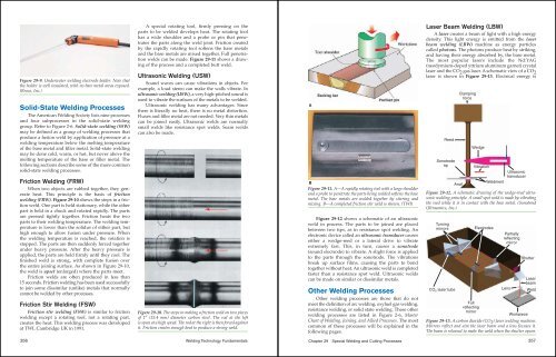
Laser Beam Welding (LBW)<br />
A laser creates a beam of light with a high energy<br />
density. This light energy is emitted from the laser<br />
beam welding (LBW) machine as energy particles<br />
called photons. The photons produce heat by striking,<br />
and having their energy absorbed by, the base metal.<br />
The most popular lasers include the Nd:YAG<br />
(neodymium-doped yttrium aluminum garnet) crystal<br />
laser and the CO 2 gas laser. A schematic view of a CO 2<br />
laser is shown in Figure <strong>29</strong>-13. Electrical energy is<br />
Reed<br />
Sonotrode<br />
tip<br />
Anvil<br />
Clamping<br />
force<br />
Wedge<br />
Vibration<br />
Weldment<br />
Ultrasonic<br />
transducer<br />
Figure <strong>29</strong>-12. A schematic drawing of the wedge-reed ultrasonic<br />
welding principle. A small spot weld is made by vibrating<br />
the reed while it is in contact with the base metal. (Sonobond<br />
Ultrasonics, Inc.)<br />
Turning<br />
mirrors<br />
CO 2 laser tube<br />
Full<br />
reflecting<br />
mirror<br />
Electrodes<br />
Partially<br />
reflecting<br />
mirror<br />
Shutter<br />
Laser<br />
beam<br />
Lens Weld<br />
Workpiece<br />
Figure <strong>29</strong>-13. A carbon dioxide (CO 2 ) laser welding machine.<br />
Mirrors reflect and aim the laser beam and a lens focuses it.<br />
The beam is released to make the weld when the shutter opens.<br />
357