
You also want an ePaper? Increase the reach of your titles
YUMPU automatically turns print PDFs into web optimized ePapers that Google loves.
generally used to excite the lasing material in the laser<br />
source, releasing photons. Photon energy is allowed to<br />
build up in the laser or laser welding machine until the<br />
desired level is reached. The energy is then released to<br />
fuse the weld joint.<br />
Fusion occurs at the point where the laser beam<br />
strikes the weldment. Laser beams may be continuous<br />
or pulsed. They can be focused with lenses to a very<br />
small and accurate beam. Their direction can be<br />
changed through the use of mirrors.<br />
Electron Beam Welding (EBW)<br />
Figure <strong>29</strong>-14 shows the basic parts of an electron<br />
beam welding (EBW) machine. Electrons are emitted<br />
from the electron gun. They are then focused and<br />
directed at the weld joint. The kinetic energy of the<br />
electrons creates the heat for welding. Kinetic energy<br />
is the energy of an object in motion. In this case, the<br />
objects in motion are the electrons.<br />
Electron beam welding may be done in a high vacuum,<br />
a partial vacuum, or under normal atmosphere<br />
pressure. A vacuum is a condition in which atmospheric<br />
pressure in a closed vessel has been decreased.<br />
This is done by pumping out air. Figure <strong>29</strong>-15 shows<br />
an electron beam welder in use in industry. The<br />
beam energy is easier to direct under high vacuum<br />
conditions. Also, less energy is lost in a vacuum.<br />
358<br />
Column<br />
valve<br />
Optics<br />
Magnetic lens<br />
Deflection coil<br />
High vacuum<br />
3″ 75 mm<br />
Base metal Weld joint<br />
Upper<br />
column<br />
Electron<br />
gun<br />
Vacuum<br />
chamber<br />
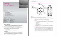
Figure <strong>29</strong>-14. The basic parts of an electron beam welding<br />
machine shown in schematic form. Note that, in this machine,<br />
the weldment is mounted in a vacuum chamber. (PTR-Precision<br />
Technologies, Inc.)<br />
Advantages of Laser and Electron<br />
Beam Welding<br />
Laser and electron beam welding machines are<br />
made in a variety of energy levels. The greater the electrical<br />
energy input, the greater the energy output.<br />
Nd:YAG lasers are produced in sizes from 100W–4000W<br />
(watts). CO 2 lasers are produced in sizes from<br />
500W–25,000W. A 600W Nd:YAG laser will penetrate<br />
steel .01″ (2.5 mm) in thickness.<br />
Electron beam welding machines are produced in<br />
sizes from 1kW–100kW (kilowatts). A 100kW EB<br />
welding machine will produce 100% penetration on<br />
steel 10″ (254 mm) thick. See Figure <strong>29</strong>-16. Laser beam<br />
and electron beam welding offer these advantages:<br />
Figure <strong>29</strong>-15. This electron beam welding machine comes with<br />
an optical viewing system, video, wire feed, vacuum chamber,<br />
and CNC technology. (PTR-Precision Technologies, Inc.)<br />
Figure <strong>29</strong>-16. A cross section of an electron beam weld. Notice<br />
how thin the weld is in relation to the metal thickness.<br />
(PTR-Precision Technologies, Inc.)<br />
Welding Technology Fundamentals<br />
• Low heat input.<br />
• Controlled welding atmospheres.<br />
• The ability to weld dissimilar metals.<br />
• The ability to weld parts as thin as .001″–.002″<br />
(.025 mm–.050 mm).<br />
• No need for filler metal.<br />
• Very precise aiming of beams to produce<br />
accurate and repeatable welds.<br />
Special Cutting Processes<br />
Special cutting processes using oxyfuel gas and<br />
oxygen arc cutting equipment have been developed<br />
for use in underwater salvaging and repairs. Other<br />
special thermal cutting processes were developed to<br />
6<br />
5<br />
4<br />
3<br />
2<br />
1<br />
7<br />
23<br />
<strong>Chapter</strong> <strong>29</strong> Special Welding and Cutting Processes<br />
8<br />
9<br />
25<br />
24<br />
10 11<br />
26<br />
27<br />
12<br />
28<br />
permit the cutting of nonferrous metals and even concrete.<br />
These processes make it possible to cut metals<br />
that cannot be cut using regular oxyfuel gas cutting.<br />
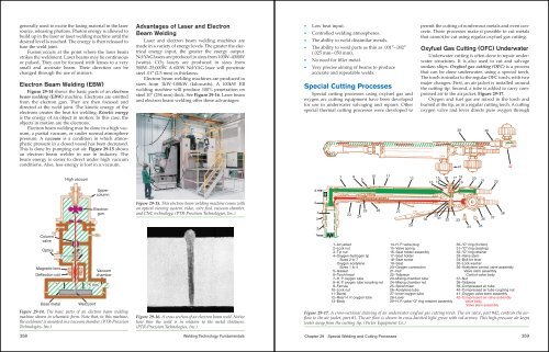
Oxyfuel Gas Cutting (OFC) Underwater<br />
Underwater cutting is often done to repair underwater<br />
structures. It is also used to cut and salvage<br />
sunken ships. Oxyfuel gas cutting (OFC) is a process<br />
that can be done underwater, using a special torch.<br />
The torch is similar to the regular OFC torch, with two<br />
major changes. First, an air jacket is installed around<br />
the cutting tip. Second, a tube is added to carry compressed<br />
air to the air jacket, Figure <strong>29</strong>-17.<br />
Oxygen and fuel gas are mixed in the torch and<br />
burned at the tip, as in a regular cutting torch. A cutting<br />
oxygen valve and lever directs pure oxygen through<br />
39 40<br />
1–Air jacket 14–H. P. valve plug 30–“O” ring (friction)<br />
2–Lock nut 15–Valve spring 31–“O” ring (sealing)<br />
3–Tip nut 16–Seat holder assembly 32–“O” ring retainer<br />
4–Oxygen-hydrogen tip 17–Seat holder 33–Valve stem<br />
Sizes 2 to 7 18–Seat screw 34–Bolt for lever<br />
Oxygen acetylene 19–Seat 35–Lock washer<br />
Sizes 1 to 4 20–Oxygen connection 36–Acetylene control valve assembly<br />
5–Gasket 21–Nut Valve stem assembly<br />
6–Torch head 22–Tailpiece Control valve body<br />
7–H. P. oxygen tube 23–Mixing chamber tube 37–Nut<br />
8–H. P. oxygen tube coupling nut 24–Mixing chamber nut 38–Tailpiece<br />
9–Ferrule 25–Spiral mixer 39–Compressed air tube<br />
10–Lock nut 26–Acetylene tube 40–Compressed air tube coupling nut<br />
11–Barrel 27–Inner oxygen tube 41–Oxygen valve stem assembly<br />
12–Rear H. P. oxygen tube 28–Lever 42–Compressed air valve assembly<br />
13–Body <strong>29</strong>–H. P. valve “O” ring retainer assembly Valve body<br />
Valve stem assembly<br />
30<br />
15<br />
13 14<br />
16 17<br />
Figure <strong>29</strong>-17. A cross-sectional drawing of an underwater oxyfuel gas cutting torch. The air valve, part #42, controls the airflow<br />
to the air jacket, part #1. The air flow is shown in cross-hatched light green with red arrows. This high-pressure air keeps<br />
water away from the cutting tip. (Victor Equipment Co.)<br />
<strong>29</strong><br />
31<br />
OXY<br />
32<br />
41<br />
33<br />
18<br />
19<br />
34<br />
20<br />
21<br />
36<br />
35<br />
37<br />
22<br />
38<br />
42<br />
359