Modeling And Analysis Of Buck-Boost DC/DC Pulse Converter XII ...
Modeling And Analysis Of Buck-Boost DC/DC Pulse Converter XII ...
Modeling And Analysis Of Buck-Boost DC/DC Pulse Converter XII ...

You also want an ePaper? Increase the reach of your titles
YUMPU automatically turns print PDFs into web optimized ePapers that Google loves.
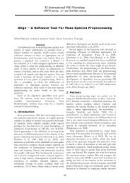
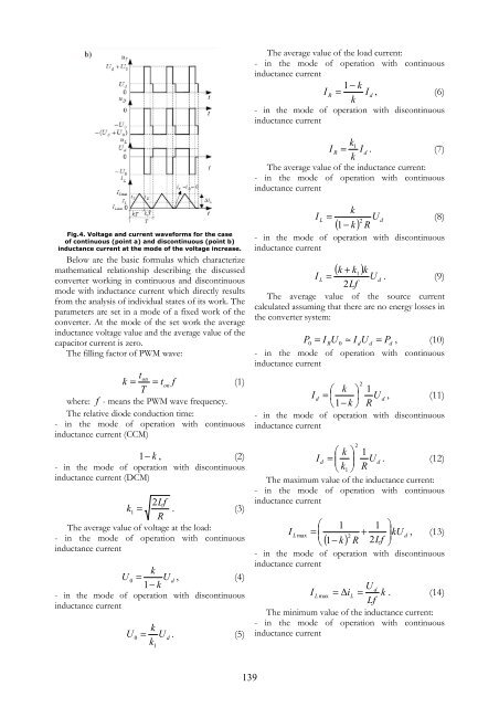
Fig.4. Voltage and current waveforms for the case<br />
of continuous (point a) and discontinuous (point b)<br />
inductance current at the mode of the voltage increase.<br />
Below are the basic formulas which characterize<br />
mathematical relationship describing the discussed<br />
converter working in continuous and discontinuous<br />
mode with inductance current which directly results<br />
from the analysis of individual states of its work. The<br />
parameters are set in a mode of a fixed work of the<br />
converter. At the mode of the set work the average<br />
inductance voltage value and the average value of the<br />
capacitor current is zero.<br />
The filling factor of PWM wave:<br />
ton<br />
k = = ton<br />
f<br />
(1)<br />
T<br />
where: f - means the PWM wave frequency.<br />
The relative diode conduction time:<br />
- in the mode of operation with continuous<br />
inductance current (CCM)<br />
1 − k , (2)<br />
- in the mode of operation with discontinuous<br />
inductance current (<strong>DC</strong>M)<br />
2Lf<br />
k1<br />
= . (3)<br />
R<br />
The average value of voltage at the load:<br />
- in the mode of operation with continuous<br />
inductance current<br />
d U<br />
k<br />
U 0 = , (4)<br />
1−<br />
k<br />
- in the mode of operation with discontinuous<br />
inductance current<br />
U<br />
0<br />
d U<br />
k<br />
= . (5)<br />
k<br />
1<br />
139<br />
The average value of the load current:<br />
- in the mode of operation with continuous<br />
inductance current<br />
− k<br />
I = I<br />
1<br />
, (6)<br />
R<br />
- in the mode of operation with discontinuous<br />
inductance current<br />
k1<br />
I R = I d . (7)<br />
k<br />
The average value of the inductance current:<br />
- in the mode of operation with continuous<br />
inductance current<br />
k<br />
I L = U d<br />
(8)<br />
2 ( 1− k)<br />
R<br />
- in the mode of operation with discontinuous<br />
inductance current<br />
k<br />
( k + k )<br />
1 k<br />
I L = U d . (9)<br />
2Lf<br />
The average value of the source current<br />
calculated assuming that there are no energy losses in<br />
the converter system:<br />
P =<br />
- in the mode of operation with continuous<br />
inductance current<br />
d<br />
0 = I RU<br />
0 ≈ I dU<br />
d Pd<br />
, (10)<br />
⎛ k ⎞ 1<br />
I d = ⎜ ⎟ U d , (11)<br />
⎝1<br />
− k ⎠ R<br />
- in the mode of operation with discontinuous<br />
inductance current<br />
⎛ k ⎞ 1<br />
I d = ⎜ U d<br />
k ⎟ . (12)<br />
⎝ 1 ⎠ R<br />
The maximum value of the inductance current:<br />
- in the mode of operation with continuous<br />
inductance current<br />
⎛ 1 1 ⎞<br />
I ⎜<br />
⎟<br />
L max =<br />
⎜<br />
+ kU d<br />
( k)<br />
R Lf ⎟<br />
, (13)<br />
2<br />
⎝ 1−<br />
2 ⎠<br />
- in the mode of operation with discontinuous<br />
inductance current<br />
U d<br />
I L max = ∆iL<br />
= k . (14)<br />
Lf<br />
The minimum value of the inductance current:<br />
- in the mode of operation with continuous<br />
inductance current<br />
2<br />
2