PRO A CABINET - Foster Spares & Service
PRO A CABINET - Foster Spares & Service
PRO A CABINET - Foster Spares & Service

You also want an ePaper? Increase the reach of your titles
YUMPU automatically turns print PDFs into web optimized ePapers that Google loves.
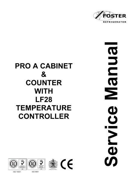
<strong>PRO</strong> A <strong>CABINET</strong><br />
&<br />
COUNTER<br />
WITH<br />
LF28<br />
TEMPERATURE<br />
CONTROLLER<br />
ISO 14001 ISO 9001
Contents<br />
Environmental Management Policy 1<br />
Disposal Requirements 1<br />
Cabinet description 2<br />
Controller Operation 2 to 4<br />
Information Menu 4<br />
Parameter Setting and Adjustment 4<br />
Fuzzy Logic 4 to 5<br />
Controller Electrical Connections 5<br />
Probe Resistance Values 5<br />
Parameters Cabinets & Counters 6 to 11<br />
Parameters Bakery Cabinets & Counters 12 to 14<br />
Technical Specification 15<br />
Wiring Diagrams 16 to 17<br />
Environmental Management Policy for <strong>Service</strong> Manuals and Duets.<br />
Product Support and Installation Contractors<br />
<strong>Foster</strong> Refrigerator recognises that its activities, products and services can have an adverse impact upon the<br />
environment.<br />
The organisation is committed to implementing systems and controls to manage, reduce and eliminate its adverse<br />
environmental impacts wherever possible, and has formulated an Environmental Policy outlining our core aims. A<br />
copy of the Environmental Policy is available to all contractors and suppliers upon request.<br />
The organisation is committed to working with suppliers and contractors where their activities have the potential to<br />
impact upon the environment. To achieve the aims stated in the Environmental Policy we require that all suppliers<br />
and contractors operate in compliance with the law and are committed to best practice in environmental<br />
management.<br />
Product Support and Installation contractors are required to:<br />
1. Ensure that wherever possible waste is removed from the client’s site, where arrangements are in place all<br />
waste should be returned to <strong>Foster</strong> Refrigerator’s premises. In certain circumstances waste may be disposed<br />
of on the clients site; if permission is given, if the client has arrangements in place for the type of waste.<br />
2. If arranging for the disposal of your waste, handle, store and dispose of it in such a way as to prevent its<br />
escape into the environment, harm to human health, and to ensure the compliance with the environmental law.<br />
Guidance is available from the Environment Agency on how to comply with the waste management ‘duty of<br />
care’.<br />
3. The following waste must be stored of separately from other wastes, as they are hazardous to the environment:<br />
refrigerants, polyurethane foam, oils.<br />
4. When arranging for disposal of waste, ensure a waste transfer note or consignment note is completed as<br />
appropriate. Ensure that all waste is correctly described on the waste note and include the appropriate six-digit<br />
code from the European Waste Catalogue. Your waste contractor or <strong>Foster</strong> can provide further information if<br />
necessary.<br />
5. Ensure that all waste is removed by a registered waste carrier, a carrier in possession of a waste management<br />
licence, or a carrier holding an appropriate exemption. Ensure the person receiving the waste at its ultimate<br />
destination is in receipt of a waste management licence or valid exemption.<br />
6. Handle and store refrigerants in such a way as to prevent their emission to atmosphere, and ensure they are<br />
disposed of safely and in accordance with environmental law.<br />
7. Make arrangements to ensure all staff who handle refrigerants do so at a level of competence consistent with<br />
the City Guilds 2078 Handling Refrigerants qualification or equivalent qualification.<br />
8. Ensure all liquid substances are securely stored to prevent leaks and spill, and are not disposed of to storm<br />
drains, foul drain, surface water to soil.<br />
DISPOSAL REQUIREMENTS<br />
If not disposed of properly all refrigerators have components that can be harmful to the environment. All old<br />
refrigerators must be disposed of by appropriately registered and licensed waste contractors, and in accordance<br />
with national laws and regulations.<br />
1
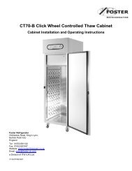
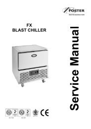
Cabinet Description<br />
Pro cabinets.<br />
The Pro range consists of a choice of capacities and temperature ranges in the full gastronorm format (650 x 530<br />
shelf) and the non gastronorm (530x 550 shelf) formats.<br />
The cabinets are manufactured as a one piece foam shell with easy clean stainless steel exterior<br />
The cabinets conform to current legislation and exceed the Montreal protocol using zero ODP refrigerants and<br />
insulation with Hydrocarbon refrigerant as an option.<br />
There are 3 temperature options exceeding Climate Class 5 operation up to 43°c ambient.<br />
Temperature is controlled by a LAE microprocessor control with digital temperature display.<br />
The standard refrigeration system is integral with an air-cooled condensing unit with the refrigerant distribution into<br />
the evaporator controlled by capillary.<br />
Remote systems are available as an option with the refrigerant distribution into the evaporator controlled by<br />
expansion valve.<br />
The cooled air is circulated through the evaporator, via the fan into the storage area.<br />
Easy removable plug box and lid.<br />
Coated coils prevent corrosion and prolong refrigeration life.<br />
Removable thermal break giving easy access to the door frame heater.<br />
Easy to read temperature display with wipe clean finish.<br />
Wide magnetic gasket giving a positive door seal.<br />
Pro counters.<br />
The Pro range consists of a choice of capacities and temperature ranges in the full gastronorm format (650 x 530<br />
shelf) and the non gastronorm (530x 550 shelf) formats.<br />
The cabinets are manufactured as a one piece foam shell with easy clean stainless steel exterior<br />
The cabinets conform to current legislation and exceed the Montreal protocol using zero ODP refrigerants and<br />
insulation with Hydrocarbon refrigerant as an option.<br />
There are 3 temperature options exceeding Climate Class 5 operation up to 43°c ambient.<br />
Temperature is controlled by a LAE microprocessor control with digital temperature display.<br />
The standard refrigeration system is integral with an air-cooled condensing unit with the refrigerant distribution into<br />
the evaporator controlled by capillary.<br />
Remote systems are available as an option with the refrigerant distribution into the evaporator controlled by<br />
expansion valve.<br />
The cooled air is circulated through the evaporator, via the fan into the storage area.<br />
Easy accessible condensing unit fitted on slides for ease of servicing.<br />
Coated coils prevent corrosion and prolong refrigeration life.<br />
Removable thermal break giving easy access to the door frame heater.<br />
Easy to read temperature display with wipe clean finish.<br />
Wide magnetic gasket giving a positive door seal.<br />
Controller Operation<br />
LF 28B2SE-B (00-555920) Controller<br />
Operation Guidelines<br />
Initial Start Up.<br />
LCD 16 Display (00-555740)<br />
Start Up & self Test:<br />
The indication is only displayed during the first three seconds following the mains electrical power being applied to<br />
the unit. During this period the controller performs a self-check.<br />
Once the self-check has been completed OFF<br />
will be displayed.<br />
Press and hold for three seconds. The unit will start and the air temperature will be displayed.<br />
2
Check temperature set point.<br />
Important to note that the ability to increase and decrease the set point is not a function available to the user as the<br />
set point is fixed. To make adjustments to the set point it is necessary to access the parameter and alter SPL and<br />
SPH accordingly.<br />
Check set point by pressing the button<br />
To increase set point press + until required temperature is displayed.<br />
To decrease set point press + until required temperature is displayed.<br />
Factory Temperature Set Point<br />
Refrigerator +1°C to +4°C<br />
Meat 0°C to 2°C.<br />
Freezer -18°C to -21°C.<br />
Exit from set up occurs after 10 seconds if no button is pressed.<br />
Manual Defrost.<br />
To initiate a manual defrost press and dEF hold will be displayed release.<br />
On completion of the defrost REC will be displayed until the cabinet temperature is achieved and then it will<br />
revert to displaying the normal cabinet temperature.<br />
Set Unit to Standby.<br />
Press display shows<br />
This indication is displayed while the unit is not operating but with mains power applied to the unit. This mode may<br />
be used for internal cleaning regimes and short periods when the unit is not required.<br />
For extended periods of inactivity the mains supply should be isolated.<br />
Alarm and Warnings<br />
High temperature alarm<br />
HI Will be displayed.<br />
The alarm will sound but can be silenced by pressing any of the buttons, however it will return after the<br />
pre-set designated period. The unit returning to normal operating temperature will automatically cancel the alarm.<br />
Possible Causes: Evaporator fan not working. Restricted airflow through airduct. Evaporator iced up. Compressor<br />
not working.<br />
Low temperature alarm.<br />
LO<br />
Will be displayed.<br />
The alarm will sound but can be silenced by pressing any of the buttons and the unit will continue to operate,<br />
however it will return after the pre-set designated period. The unit returning to normal operating temperature will<br />
automatically cancel the alarm.<br />
Possible Causes: Controller faulty (not switching compressor off). Compressor secondary relay will not deenergise<br />
(low temperature models).<br />
Door Open Alarm. (Only applies to cabinets fitted with door switches.)<br />
DO<br />
Will be displayed.<br />
The alarm will sound but can be silenced by pressing.<br />
The display will continue to display the alarm message until cancelled by shutting the door.<br />
If the alarm cannot be cancelled by doing this call your <strong>Foster</strong> Authorised <strong>Service</strong> Company.<br />
Possible Causes: Faulty door switch. Door left open for more than 5minutes.<br />
High Pressure Alarm (Only applies to machines fitted with a condenser probe).<br />
HP<br />
Will be displayed<br />
This alarm relate to the condenser which must be checked and cleaned at regular intervals the frequency being<br />
determined by site conditions.<br />
The alarm will sound but can be silenced by pressing any of the buttons and the unit will continue to operate,<br />
however it will return after the pre-set designated period. The unit returning to normal operating temperature will<br />
automatically cancel the alarm.<br />
Possible Causes: Condenser fan not working. Condenser blocked/ dirty. Condenser obstructed.<br />
Air Temperature Probe Failure.<br />
OFF<br />
3
E1<br />
Will be displayed.<br />
The alarm will sound but can be silenced by pressing any button.<br />
There is no further action that can be taken by the user in this instance. During this period the unit will continue to<br />
operate but have a reduced performance.<br />
Action: Replace Probe.<br />
Evaporator Temperature Probe Failure. (Automatic Defrost Cabinets Only)<br />
E2 Will be displayed.<br />
The alarm will sound but can be silenced by pressing any button.<br />
There is no further action that can be taken by the user in this instance. During this period the unit will continue to<br />
operate satisfactorily, but this failure will have an effect on the defrost and therefore efficiency if allowed to<br />
continue.<br />
Action: Replace Probe.<br />
Information Menu<br />
Pressing and releasing activates the information menu. From this menu you can display the<br />
temperature relating to T1 (air probe), T2 (evaporator probe, if fitted) and T3 (condenser probe, if fitted).<br />
The maximum temperature (THI) and the minimum temperature (TLO) the cabinet has achieved since it was last<br />
re-set.<br />
The total operating time of the condenser (CND), since it was last cleaned, and the keyboard status (LOC).<br />
The information to be displayed can be selected sequentially by pressing repeatedly or scrolling<br />
through the menu using the or buttons.<br />
Once selected press to display the value<br />
Exit from the info menu by pressing or is automatic after 6 seconds if no buttons are pressed.<br />
To reset the temperature settings recorded in THI and TLO and the hours counted in CND, access the info menu<br />
press to display the value plus simultaneously for resetting to be completed.<br />
To check the LOC status scroll through to LOC, press to display status – YES to lock keys. – NO to leave keys<br />
accessible.<br />
NOTE: with the keys locked it is not possible to turn the unit off or ON or to check the set point<br />
Parameter Setting and Adjustment<br />
It is strongly advised that before adjusting any <strong>Service</strong> Parameters a thorough understanding of the<br />
following instructions should be obtained.<br />
The parameters are accessed by pressing the following keys in succession +<br />
and keeping them pressed for 5 seconds.<br />
After this period the first parameter ‘SCL’ will be displayed.<br />
Press button to pass from one parameter to the next and button to go back.<br />
Press to display the value + or to change it.<br />
Exit from set up is by pressing or is automatic if no buttons are pressed for 30 seconds<br />
Fuzzy Logic.<br />
These are settings that maintain the temperature of the cabinet in a more energy efficient manner.<br />
It works by controlling the evaporator fan/s, defrost and temperature in low usage times by transferring the<br />
operation to a second set of economy parameters.<br />
When the cabinet is first switched On the economy settings control the operation of the temperature and will remain<br />
at those settings until the controller, by monitoring the door opening frequency and the air and evaporator<br />
temperatures, identifies a higher usage and switches over to the 11SM (2nd parameter set management).<br />
When the economy settings are activated the cabinet temperature is allowed to rise to the setting (SP) setpoint [1].<br />
This is set to a higher temperature setting to allow the air temperature to rise without having much of an impact on<br />
the product temperature.<br />
4
In addition the fan/s will modulate (cycle for 30 seconds) as set in (FPC) evaporator fan On / Off Ratio.<br />
The parameter is set at 1.<br />
Changing the setting to 0 will have the fan running with the compressor. Set to 1 the fan will run for 30 seconds on<br />
and 60 seconds off. Set to 2 the fan will run for 60 seconds on and 60 seconds off and set to 3 the fan will run for<br />
90 seconds on and 60 seconds off.<br />
With FPC set to 1, 2 or 3 the fans will generate less heat into the cabinet therefore reduce the requirement of the<br />
condensing system.<br />
NOTE:<br />
Parameter FPC will only function with the parameter FTC set for YES. With FTC set to NO the fan will run all of the<br />
time apart from during defrost when it will be off during electric and hot gas defrost but on during a timed off cycle<br />
defrost.<br />
Fan Operation.<br />
The evaporator fan/s will run normally when the compressor is running but will commence cycling when the<br />
compressor is in the off cycle mode.<br />
The fans will run without the compressor during timed off cycle defrost but will not run during hot gas or electric<br />
defrost.<br />
For models that don’t have door switches fitted the fuzzy logic will not function as the controller is unable to monitor<br />
door opening factors.<br />
Auto Defrost operation.<br />
The defrost frequency is determined by the usage of the machine.<br />
In the economy mode it may not perform a defrost as by monitoring the air temperature, evaporator temperature<br />
and door opening factor it may decide that there is insufficient ice build up on the evaporator so defrosting is not<br />
required.<br />
The parameter DFR (defrost frequency) is set for 3. The cabinet will perform at least 1 defrost per day and with the<br />
setting at 3 it has the potential to initiate up to 2 additional defrost in the economy mode.<br />
Should the cabinet experience constant usage the controller will switch automatically to the second parameter<br />
settings indicated by the controller LED adjacent to illuminating, which could under circumstances of heavy<br />
usage initiate up to 6 defrosts per day.<br />
The second parameter settings preceded by 11 will now be active,<br />
It is important to note that during the first few days of operation the defrosting frequency may be at regular intervals<br />
but these will reduce as the controller monitors the operation.<br />
Controller Electrical Connections<br />
Probes<br />
Air and Evaporator Probes<br />
The air and evaporator probes are the same and are identified as T1 Air Probe and T2 Evaporator Probe. These<br />
are the K2 NTC thermistor type and are fully enclosed to make it completely waterproof and resilient to temperature<br />
variation within the limits of rapid cycling. The probe is capable of measuring temperature in excess of -30°C and<br />
50°C with 1°K accuracy at 1°C and no more than 2°K at the upper and lower temperature ranges.<br />
Probe temperature resistance values<br />
°C K ohm °C K ohm °C K ohm °C K ohm °C K ohm<br />
-25 19.402 -15 11.644 5 4.571 15 2.987 25 2<br />
-20 14.961 -10 8.133 10 3.682 20 2.437 40 1.143<br />
5
F 28B2SE-B (00-555920) Controller Parameter lists<br />
Parameter list for High Temperature cabinets including: -<br />
<strong>PRO</strong>B600H-A, <strong>PRO</strong>G1100H-A, <strong>PRO</strong>G1350H, <strong>PRO</strong>G1350HP-A, <strong>PRO</strong>G 300/300HH-A, <strong>PRO</strong>G500H-A,<br />
<strong>PRO</strong>G600H-A, <strong>PRO</strong>G600HP-A, <strong>PRO</strong>G600HE-A, <strong>PRO</strong>S400H-A, PSG1100H-A, PSG1350H-A, PSG300/300H-A,<br />
PSG500H-A, PSG600H-A, PSG600HE-A, PSS1000H-A, PSS450H-A. Also remote condensing unit models (R).<br />
Parameter list for High Temperature counters including: -<br />
LL1/2H-A, <strong>PRO</strong>1/2H-A, <strong>PRO</strong>1/2HR-A, <strong>PRO</strong>1/3H-A, <strong>PRO</strong>1/3HR-A, <strong>PRO</strong>1/4H-A, <strong>PRO</strong>1/4HR-A, <strong>PRO</strong>2/1H-A,<br />
<strong>PRO</strong>2/1HR-A, <strong>PRO</strong>2/2H-A, <strong>PRO</strong>2/2HR-A, <strong>PRO</strong>2/3H-A, <strong>PRO</strong>2/3HR-A, Also remote condensing unit models (R).<br />
Note: For all counters adjust parameter ‘DS’ to NO as door switches are not fitted to these models.<br />
Mnem. Definition Min. Max Default Dim. HT<br />
SCL Readout scale 1°C; 2°C; °F 2 flag 2<br />
SPL Minimum setpoint [ I ] -40 SPH 1 °C 1<br />
SPH Maximum setpoint [ I ] SPL 40 3 °C 3<br />
SP Setpoint [ I ] SPL SPH 2 °C 2<br />
HYS Thermostat hysteresis [ I ] 0.1 10 3 °K 3<br />
CRT Minimum compressor rest time 0 30 2 min. 2<br />
CT1 Compressor run with T1 failure 0 30 7 min. 7<br />
CT2 Compressor stop with T1 failure 0 30 3 min. 3<br />
2CD Start delay 2nd compressor 0 120 0 sec. 0<br />
DFR Defrost frequency / 24h 0 24 2 1/24h 2<br />
DLI Defrost end temperature -40 40 20 °C 20<br />
DTO Maximum defrost duration 1 120 20 min. 20<br />
DTY Defrost type OFF; ELE; GAS OFF flag OFF<br />
DRN Drain down time 0 30 2 min. 2<br />
DDY Defrost display control 0 60 10 min. 10<br />
FID Fan activity during defrost NO YES YES flag YES<br />
FDD Fan re-start delay temperature -40 40 0 °C 0<br />
FTO Evaporator fan maximum time-out 0 120 3 min. 3<br />
FTC Evaporator fan timed control NO YES YES flag YES<br />
FT1 Fan stop delay 0 180 15 sec. 15<br />
FT2 Timed fan stop 0 30 2 min. 2<br />
FT3 Timed fan run 0 30 1 min. 1<br />
ATL Low alarm differential -12 0 -5 °K -5<br />
ATH High alarm differential 0 12 5 °K 5<br />
ATD Alarm Temperature Delay 0 120 90 min. 90<br />
AHT Condenser Alarm Temperature 0 75 60 °C 60<br />
AHM Condenser high temp. alarm operation NON; ALR; STP NON flag NON<br />
ACC Condenser cleaning period 0 52 0 wks 0<br />
HDS Sensitivity function eco / heavy duty 1 5 3 flag 3<br />
IISM 2nd parameter set switching mode NON; MAN; HDD; DI2 HDD flag HDD<br />
IISL Minimum 2nd temp. set -40 IISH 1 °C 1<br />
IISH Maximum 2nd temp. set IISL 40 3 °C 3<br />
IISP Effective 2nd temperature set point IISL IISH 1 °C 1<br />
IIHY Hysteresis 2nd temperature set 0.1 10 3 °K 3<br />
IIFT Evap. fan timed control in mode 2 NO YES NO flag NO<br />
IIDF Defrost Frequency / 24h in mode 2 0 24 4 1/24h 4<br />
SB Button 0/1 enabling NO YES YES flag YES<br />
DS Door switch enabling NO YES YES flag YES<br />
CSD Compressor stop delay from door opening 0 30 1 min. 1<br />
ADO Door alarm delay 0 30 8 min. 8<br />
D12 Function digital input D12 NON; HPS; IISM; RDS NON flag NON<br />
LSM Light switch mode NON; MAN; DOR NON flag NON<br />
OAU Control of AUX output NON; 0-1; LGT; 2CU; 2EU; ALR NON flag NON<br />
OS1 T1 (air) probe offset -12 12 0 °K 0<br />
T2 T2 (evap.) probe enabling NO YES NO flag NO<br />
OS2 T2 (evap.) probe offset -12 12 0 °K 0<br />
T3 T3 (cond.) probe enabling NO YES NO flag NO<br />
OS3 T3 (cond.) probe offset -12 12 0 °K 0<br />
T4 T4 (aux.) probe enabling NON; 2CU; 2EU NON flag NON<br />
OS4 T4 (aux.) probe offset -12 12 0 °K 0<br />
TLD Delay for min./max. temp storage 1 30 5 min. 5<br />
SIM Display slowdown 0 100 3 exp. 3<br />
ADR Unit peripheral address 1 255 1 exp. 1<br />
6
Parameter list for Low Temperature cabinets with hot gas defrost including: -<br />
<strong>PRO</strong>B600L-A, <strong>PRO</strong>G1100L-A, <strong>PRO</strong>G1350L-A, <strong>PRO</strong>G300/300L-A, <strong>PRO</strong>G500L-A, <strong>PRO</strong>G600L-A, <strong>PRO</strong>G600LE-A,<br />
<strong>PRO</strong>S400L-A, PSG1100L-A, PSG1350L-A, PSG300/300L-A, PSG500L-A, PSG600L-A, PSG600LE-A.<br />
PSS1000L-A<br />
Parameter list for Low Temperature counters with hot gas defrost including: -<br />
<strong>PRO</strong>1/2L-A, <strong>PRO</strong>1/3L-A, <strong>PRO</strong>1/4L-A, <strong>PRO</strong>2/1L-A, <strong>PRO</strong>2/2L-A, <strong>PRO</strong>2/3L-A,<br />
Note: For all counters adjust parameter ‘DS’ to NO as door switches are not fitted to these models.<br />
Mnem. Definition Min. Max Default Dim. LT Gas<br />
SCL Readout scale 1°C; 2°C; °F 2 flag 2<br />
SPL Minimum setpoint [ I ] -40 SPH 1 °C -21<br />
SPH Maximum setpoint [ I ] SPL 40 3 °C -19<br />
SP Setpoint [ I ] SPL SPH 2 °C -19<br />
HYS Thermostat hysteresis [ I ] 0.1 10 3 °K 3<br />
CRT Minimum compressor rest time 0 30 2 min. 2<br />
CT1 Compressor run with T1 failure 0 30 7 min. 7<br />
CT2 Compressor stop with T1 failure 0 30 3 min. 3<br />
2CD Start delay 2nd compressor 0 120 0 sec. 0<br />
DFR Defrost frequency / 24h 0 24 2 1/24h 4<br />
DLI Defrost end temperature -40 40 20 °C 20<br />
DTO Maximum defrost duration 1 120 20 min. 20<br />
DTY Defrost type OFF; ELE; GAS OFF flag GAS<br />
DRN Drain down time 0 30 2 min. 2<br />
DDY Defrost display control 0 60 10 min. 10<br />
FID Fan activity during defrost NO YES YES flag NO<br />
FDD Fan re-start delay temperature -40 40 0 °C 0<br />
FTO Evaporator fan maximum time-out 0 120 3 min. 3<br />
FTC Evaporator fan timed control NO YES YES flag YES<br />
FT1 Fan stop delay 0 180 15 sec. 15<br />
FT2 Timed fan stop 0 30 2 min. 3<br />
FT3 Timed fan run 0 30 1 min. 1<br />
ATL Low alarm differential -12 0 -5 °K -5<br />
ATH High alarm differential 0 12 5 °K 5<br />
ATD Alarm Temperature Delay 0 120 90 min. 90<br />
AHT Condenser Alarm Temperature 0 75 60 °C 60<br />
AHM Condenser high temp. alarm operation NON; ALR; STP NON flag NON<br />
ACC Condenser cleaning period 0 52 0 wks 0<br />
HDS Sensitivity function eco / heavy duty 1 5 3 flag 3<br />
IISM 2nd parameter set switching mode NON; MAN; HDD; DI2 HDD flag HDD<br />
IISL Minimum 2nd temp. set -40 IISH 1 °C -21<br />
IISH Maximum 2nd temp. set IISL 40 3 °C -21<br />
IISP Effective 2nd temperature set point IISL IISH 1 °C -21<br />
IIHY Hysteresis 2nd temperature set 0.1 10 3 °K 3<br />
IIFT Evap. fan timed control in mode 2 NO YES NO flag NO<br />
IIDF Defrost Frequency / 24h in mode 2 0 24 4 1/24h 4<br />
SB Button 0/1 enabling NO YES YES flag YES<br />
DS Door switch enabling NO YES YES flag YES<br />
CSD Compressor stop delay from door opening 0 30 1 min. 1<br />
ADO Door alarm delay 0 30 8 min. 8<br />
D12 Function digital input D12 NON; HPS; IISM; RDS NON flag NON<br />
LSM Light switch mode NON; MAN; DOR NON flag NON<br />
OAU Control of AUX output NON; 0-1; LGT; 2CU; 2EU; ALR NON flag NON<br />
OS1 T1 (air) probe offset -12 12 0 °K 0<br />
T2 T2 (evap.) probe enabling NO YES NO flag YES<br />
OS2 T2 (evap.) probe offset -12 12 0 °K 0<br />
T3 T3 (cond.) probe enabling NO YES NO flag NO<br />
OS3 T3 (cond.) probe offset -12 12 0 °K 0<br />
T4 T4 (aux.) probe enabling NON; 2CU; 2EU NON flag NON<br />
OS4 T4 (aux.) probe offset -12 12 0 °K 0<br />
TLD Delay for min./max. temp storage 1 30 5 min. 5<br />
SIM Display slowdown 0 100 3 exp. 3<br />
ADR Unit peripheral address 1 255 1 exp. 1<br />
7
Parameter list for Low Temperature cabinets with electric defrost including: -<br />
<strong>PRO</strong>B600LR-A, <strong>PRO</strong>G500LR-A. <strong>PRO</strong>G600LR-A, <strong>PRO</strong>S400LR-A, PSG500LR-A, PSG600LR-A, PSS1000L-A,<br />
PSS450L-A. <strong>PRO</strong> S 400L-A, <strong>PRO</strong> G600LU-A,<br />
<strong>PRO</strong>B600LW-A & PFB600LW for these models adjust parameter ‘DTO’ to 10.<br />
Parameter list for Low Temperature counters with electric defrost including: -<br />
<strong>PRO</strong>1/2LR-A, <strong>PRO</strong>1/3LR-A, <strong>PRO</strong>1/4LR-A, <strong>PRO</strong>2/1LR, <strong>PRO</strong>2/2LR-A, <strong>PRO</strong>2/3LR-A,<br />
Note: For all counters adjust parameter ‘DS’ to NO as door switches are not fitted to these models.<br />
Mnem. Definition Min. Max Default Dim.<br />
LT<br />
Electric<br />
SCL Readout scale 1°C; 2°C; °F 2 flag 2<br />
SPL Minimum setpoint [ I ] -40 SPH 1 °C -21<br />
SPH Maximum setpoint [ I ] SPL 40 3 °C -19<br />
SP Setpoint [ I ] SPL SPH 2 °C -19<br />
HYS Thermostat hysteresis [ I ] 0.1 10 3 °K 3<br />
CRT Minimum compressor rest time 0 30 2 min. 2<br />
CT1 Compressor run with T1 failure 0 30 7 min. 7<br />
CT2 Compressor stop with T1 failure 0 30 3 min. 3<br />
2CD Start delay 2nd compressor 0 120 0 sec. 0<br />
DFR Defrost frequency / 24h 0 24 2 1/24h 4<br />
DLI Defrost end temperature -40 40 20 °C 20<br />
DTO Maximum defrost duration 1 120 20 min. 20<br />
DTY Defrost type OFF; ELE; GAS OFF flag ELE<br />
DRN Drain down time 0 30 2 min. 2<br />
DDY Defrost display control 0 60 10 min. 10<br />
FID Fan activity during defrost NO YES YES flag NO<br />
FDD Fan re-start delay temperature -40 40 0 °C 0<br />
FTO Evaporator fan maximum time-out 0 120 3 min. 3<br />
FTC Evaporator fan timed control NO YES YES flag YES<br />
FT1 Fan stop delay 0 180 15 sec. 15<br />
FT2 Timed fan stop 0 30 2 min. 3<br />
FT3 Timed fan run 0 30 1 min. 1<br />
ATL Low alarm differential -12 0 -5 °K -5<br />
ATH High alarm differential 0 12 5 °K 5<br />
ATD Alarm Temperature Delay 0 120 90 min. 90<br />
AHT Condenser Alarm Temperature 0 75 60 °C 60<br />
AHM Condenser high temp. alarm operation NON; ALR; STP NON flag NON<br />
ACC Condenser cleaning period 0 52 0 wks 0<br />
HDS Sensitivity function eco / heavy duty 1 5 3 flag 3<br />
IISM 2nd parameter set switching mode NON; MAN; HDD; DI2 HDD flag HDD<br />
IISL Minimum 2nd temp. set -40 IISH 1 °C -21<br />
IISH Maximum 2nd temp. set IISL 40 3 °C -21<br />
IISP Effective 2nd temperature set point IISL IISH 1 °C -21<br />
IIHY Hysteresis 2nd temperature set 0.1 10 3 °K 3<br />
IIFT Evap. fan timed control in mode 2 NO YES NO flag NO<br />
IIDF Defrost Frequency / 24h in mode 2 0 24 4 1/24h 4<br />
SB Button 0/1 enabling NO YES YES flag YES<br />
DS Door switch enabling NO YES YES flag YES<br />
CSD Compressor stop delay from door opening 0 30 1 min. 1<br />
ADO Door alarm delay 0 30 8 min. 8<br />
D12 Function digital input D12 NON; HPS; IISM; RDS NON flag NON<br />
LSM Light switch mode NON; MAN; DOR NON flag NON<br />
OAU Control of AUX output NON; 0-1; LGT; 2CU; 2EU; ALR NON flag NON<br />
OS1 T1 (air) probe offset -12 12 0 °K 0<br />
T2 T2 (evap.) probe enabling NO YES NO flag YES<br />
OS2 T2 (evap.) probe offset -12 12 0 °K 0<br />
T3 T3 (cond.) probe enabling NO YES NO flag NO<br />
OS3 T3 (cond.) probe offset -12 12 0 °K 0<br />
T4 T4 (aux.) probe enabling NON; 2CU; 2EU NON flag NON<br />
OS4 T4 (aux.) probe offset -12 12 0 °K 0<br />
TLD Delay for min./max. temp storage 1 30 5 min. 5<br />
SIM Display slowdown 0 100 3 exp. 3<br />
ADR Unit peripheral address 1 255 1 exp. 1<br />
8
Parameter list for Meat Temperature cabinets with hot gas defrost including: -<br />
<strong>PRO</strong>B600M-A, <strong>PRO</strong>G1350M-A, <strong>PRO</strong>G600M-A, PSG1350M-A, PSG600M-A, <strong>PRO</strong>S525M-A, <strong>PRO</strong>S950M-A,<br />
<strong>PRO</strong>G1100M-A, <strong>PRO</strong>S1500M-A, <strong>PRO</strong>S400M-A, PSG1100M-A, PSG500M-A.<br />
Parameter list for Meat Temperature counters with hot gas defrost including: -<br />
LL2/1MD-A, LL2/1MS-A, LL2/2M-A, LL2/4M-A, <strong>PRO</strong>1/2M-A, <strong>PRO</strong>1/3M-A, <strong>PRO</strong>1/4M-A, <strong>PRO</strong>2/1M-A, <strong>PRO</strong>2/2M-A<br />
<strong>PRO</strong>2/3M-A.<br />
Note: For all counters adjust parameter ‘DS’ to NO as door switches are not fitted to these models.<br />
Mnem. Definition Min. Max Default Dim.<br />
MT<br />
Gas<br />
SCL Readout scale 1°C; 2°C; °F 2 flag 2<br />
SPL Minimum setpoint [ I ] -40 SPH 1 °C -2<br />
SPH Maximum setpoint [ I ] SPL 40 3 °C 0<br />
SP Setpoint [ I ] SPL SPH 2 °C -1<br />
HYS Thermostat hysteresis [ I ] 0.1 10 3 °K 2<br />
CRT Minimum compressor rest time 0 30 2 min. 2<br />
CT1 Compressor run with T1 failure 0 30 7 min. 7<br />
CT2 Compressor stop with T1 failure 0 30 3 min. 3<br />
2CD Start delay 2nd compressor 0 120 0 sec. 0<br />
DFR Defrost frequency / 24h 0 24 2 1/24h 4<br />
DLI Defrost end temperature -40 40 20 °C 20<br />
DTO Maximum defrost duration 1 120 20 min. 20<br />
DTY Defrost type OFF; ELE; GAS OFF flag GAS<br />
DRN Drain down time 0 30 2 min. 2<br />
DDY Defrost display control 0 60 10 min. 10<br />
FID Fan activity during defrost NO YES YES flag NO<br />
FDD Fan re-start delay temperature -40 40 0 °C 0<br />
FTO Evaporator fan maximum time-out 0 120 3 min. 3<br />
FTC Evaporator fan timed control NO YES YES flag YES<br />
FT1 Fan stop delay 0 180 15 sec. 15<br />
FT2 Timed fan stop 0 30 2 min. 3<br />
FT3 Timed fan run 0 30 1 min. 1<br />
ATL Low alarm differential -12 0 -5 °K -5<br />
ATH High alarm differential 0 12 5 °K 5<br />
ATD Alarm Temperature Delay 0 120 90 min. 90<br />
AHT Condenser Alarm Temperature 0 75 60 °C 60<br />
AHM Condenser high temp. alarm operation NON; ALR; STP NON flag NON<br />
ACC Condenser cleaning period 0 52 0 wks 0<br />
HDS Sensitivity function eco / heavy duty 1 5 3 flag 3<br />
IISM 2nd parameter set switching mode NON; MAN; HDD; DI2 HDD flag HDD<br />
IISL Minimum 2nd temp. set -40 IISH 1 °C -2<br />
IISH Maximum 2nd temp. set IISL 40 3 °C 0<br />
IISP Effective 2nd temperature set point IISL IISH 1 °C -2<br />
IIHY Hysteresis 2nd temperature set 0.1 10 3 °K 2<br />
IIFT Evap. fan timed control in mode 2 NO YES NO flag NO<br />
IIDF Defrost Frequency / 24h in mode 2 0 24 4 1/24h 4<br />
SB Button 0/1 enabling NO YES YES flag YES<br />
DS Door switch enabling NO YES YES flag YES<br />
CSD Compressor stop delay from door opening 0 30 1 min. 1<br />
ADO Door alarm delay 0 30 8 min. 8<br />
D12 Function digital input D12 NON; HPS; IISM; RDS NON flag NON<br />
LSM Light switch mode NON; MAN; DOR NON flag NON<br />
OAU Control of AUX output NON; 0-1; LGT; 2CU; 2EU; ALR NON flag NON<br />
OS1 T1 (air) probe offset -12 12 0 °K 0<br />
T2 T2 (evap.) probe enabling NO YES NO flag YES<br />
OS2 T2 (evap.) probe offset -12 12 0 °K 0<br />
T3 T3 (cond.) probe enabling NO YES NO flag NO<br />
OS3 T3 (cond.) probe offset -12 12 0 °K 0<br />
T4 T4 (aux.) probe enabling NON; 2CU; 2EU NON flag NON<br />
OS4 T4 (aux.) probe offset -12 12 0 °K 0<br />
TLD Delay for min./max. temp storage 1 30 5 min. 5<br />
SIM Display slowdown 0 100 3 exp. 3<br />
ADR Unit peripheral address 1 255 1 exp. 1<br />
9
Parameter list for Meat Temperature cabinets with electric defrost including: -<br />
<strong>PRO</strong>B600MW-A, <strong>PRO</strong>G1350MR-A, <strong>PRO</strong>G600MR-A, PSG1350MR-A, PSG600MR-A, CS1350MR-A,<br />
CS600MR-A, <strong>PRO</strong>B600MR-A, <strong>PRO</strong>G600MR-A, <strong>PRO</strong>S525MR-A, <strong>PRO</strong>S950MR-A, <strong>PRO</strong>G1100MR-A,<br />
<strong>PRO</strong>S11502MR-A, <strong>PRO</strong>S400MR-A, PSG1100MR-A, PSG500MR-A, PSS1000M-A, PSS450M-A.<br />
Parameter list for Meat Temperature counters with electric defrost including: -<br />
<strong>PRO</strong>1/2MR-A, <strong>PRO</strong>1/3MR-A, <strong>PRO</strong>1/4MR-A, <strong>PRO</strong>2/1MR-A, <strong>PRO</strong>2/2MR-A, <strong>PRO</strong>2/3MR-A.<br />
Note: For all counters adjust parameter ‘DS’ to NO as door switches are not fitted to these models.<br />
Mnem. Definition Min. Max Default Dim.<br />
MT<br />
Electric<br />
SCL Readout scale 1°C; 2°C; °F 2 flag 2<br />
SPL Minimum setpoint [ I ] -40 SPH 1 °C -2<br />
SPH Maximum setpoint [ I ] SPL 40 3 °C 0<br />
SP Setpoint [ I ] SPL SPH 2 °C -1<br />
HYS Thermostat hysteresis [ I ] 0.1 10 3 °K 2<br />
CRT Minimum compressor rest time 0 30 2 min. 2<br />
CT1 Compressor run with T1 failure 0 30 7 min. 7<br />
CT2 Compressor stop with T1 failure 0 30 3 min. 3<br />
2CD Start delay 2nd compressor 0 120 0 sec. 0<br />
DFR Defrost frequency / 24h 0 24 2 1/24h 4<br />
DLI Defrost end temperature -40 40 20 °C 20<br />
DTO Maximum defrost duration 1 120 20 min. 20<br />
DTY Defrost type OFF; ELE; GAS OFF flag ELE<br />
DRN Drain down time 0 30 2 min. 2<br />
DDY Defrost display control 0 60 10 min. 10<br />
FID Fan activity during defrost NO YES YES flag NO<br />
FDD Fan re-start delay temperature -40 40 0 °C 0<br />
FTO Evaporator fan maximum time-out 0 120 3 min. 3<br />
FTC Evaporator fan timed control NO YES YES flag YES<br />
FT1 Fan stop delay 0 180 15 sec. 15<br />
FT2 Timed fan stop 0 30 2 min. 3<br />
FT3 Timed fan run 0 30 1 min. 1<br />
ATL Low alarm differential -12 0 -5 °K -5<br />
ATH High alarm differential 0 12 5 °K 5<br />
ATD Alarm Temperature Delay 0 120 90 min. 90<br />
AHT Condenser Alarm Temperature 0 75 60 °C 60<br />
AHM Condenser high temp. alarm operation NON; ALR; STP NON flag NON<br />
ACC Condenser cleaning period 0 52 0 wks 0<br />
HDS Sensitivity function eco / heavy duty 1 5 3 flag 3<br />
IISM 2nd parameter set switching mode NON; MAN; HDD; DI2 HDD flag HDD<br />
IISL Minimum 2nd temp. set -40 IISH 1 °C -2<br />
IISH Maximum 2nd temp. set IISL 40 3 °C 0<br />
IISP Effective 2nd temperature set point IISL IISH 1 °C -2<br />
IIHY Hysteresis 2nd temperature set 0.1 10 3 °K 2<br />
IIFT Evap. fan timed control in mode 2 NO YES NO flag NO<br />
IIDF Defrost Frequency / 24h in mode 2 0 24 4 1/24h 4<br />
SB Button 0/1 enabling NO YES YES flag YES<br />
DS Door switch enabling NO YES YES flag YES<br />
CSD Compressor stop delay from door opening 0 30 1 min. 1<br />
ADO Door alarm delay 0 30 8 min. 8<br />
D12 Function digital input D12 NON; HPS; IISM; RDS NON flag NON<br />
LSM Light switch mode NON; MAN; DOR NON flag NON<br />
OAU Control of AUX output NON; 0-1; LGT; 2CU; 2EU; ALR NON flag NON<br />
OS1 T1 (air) probe offset -12 12 0 °K 0<br />
T2 T2 (evap.) probe enabling NO YES NO flag YES<br />
OS2 T2 (evap.) probe offset -12 12 0 °K 0<br />
T3 T3 (cond.) probe enabling NO YES NO flag NO<br />
OS3 T3 (cond.) probe offset -12 12 0 °K 0<br />
T4 T4 (aux.) probe enabling NON; 2CU; 2EU NON flag NON<br />
OS4 T4 (aux.) probe offset -12 12 0 °K 0<br />
TLD Delay for min./max. temp storage 1 30 5 min. 5<br />
SIM Display slowdown 0 100 3 exp. 3<br />
ADR Unit peripheral address 1 255 1 exp. 1<br />
10
Parameter list for Fish cabinets including: -<br />
<strong>PRO</strong>G1350F-A, <strong>PRO</strong>G600F-A, <strong>PRO</strong>G 400F-A,<strong>PRO</strong>S400F-A<br />
Note: For all counters adjust parameter ‘DS’ to NO as door switches are not fitted to these models.<br />
Mnem. Definition Min. Max Default Dim. FT<br />
SCL Readout scale 1°C; 2°C; °F 2 flag 2<br />
SPL Minimum setpoint [ I ] -40 SPH 1 °C -1<br />
SPH Maximum setpoint [ I ] SPL 40 3 °C 1<br />
SP Setpoint [ I ] SPL SPH 2 °C 0<br />
HYS Thermostat hysteresis [ I ] 0.1 10 3 °K 2<br />
CRT Minimum compressor rest time 0 30 2 min. 2<br />
CT1 Compressor run with T1 failure 0 30 7 min. 7<br />
CT2 Compressor stop with T1 failure 0 30 3 min. 3<br />
2CD Start delay 2nd compressor 0 120 0 sec. 0<br />
DFR Defrost frequency / 24h 0 24 2 1/24h 0<br />
DLI Defrost end temperature -40 40 20 °C 20<br />
DTO Maximum defrost duration 1 120 20 min. 20<br />
DTY Defrost type OFF; ELE; GAS OFF flag OFF<br />
DRN Drain down time 0 30 2 min. 2<br />
DDY Defrost display control 0 60 10 min. 10<br />
FID Fan activity during defrost NO YES YES flag YES<br />
FDD Fan re-start delay temperature -40 40 0 °C 0<br />
FTO Evaporator fan maximum time-out 0 120 3 min. 3<br />
FTC Evaporator fan timed control NO YES YES flag YES<br />
FT1 Fan stop delay 0 180 15 sec. 15<br />
FT2 Timed fan stop 0 30 2 min. 2<br />
FT3 Timed fan run 0 30 1 min. 1<br />
ATL Low alarm differential -12 0 -5 °K -5<br />
ATH High alarm differential 0 12 5 °K 5<br />
ATD Alarm Temperature Delay 0 120 90 min. 90<br />
AHT Condenser Alarm Temperature 0 75 60 °C 60<br />
AHM Condenser high temp. alarm operation NON; ALR; STP NON flag NON<br />
ACC Condenser cleaning period 0 52 0 wks 0<br />
HDS Sensitivity function eco / heavy duty 1 5 3 flag 3<br />
IISM 2nd parameter set switching mode NON; MAN; HDD; DI2 HDD flag HDD<br />
IISL Minimum 2nd temp. set -40 IISH 1 °C 1<br />
IISH Maximum 2nd temp. set IISL 40 3 °C 3<br />
IISP Effective 2nd temperature set point IISL IISH 1 °C 1<br />
IIHY Hysteresis 2nd temperature set 0.1 10 3 °K 3<br />
IIFT Evap. fan timed control in mode 2 NO YES NO flag NO<br />
IIDF Defrost Frequency / 24h in mode 2 0 24 4 1/24h 4<br />
SB Button 0/1 enabling NO YES YES flag YES<br />
DS Door switch enabling NO YES YES flag YES<br />
CSD Compressor stop delay from door opening 0 30 1 min. 1<br />
ADO Door alarm delay 0 30 8 min. 8<br />
D12 Function digital input D12 NON; HPS; IISM; RDS NON flag NON<br />
LSM Light switch mode NON; MAN; DOR NON flag NON<br />
OAU Control of AUX output NON; 0-1; LGT; 2CU; 2EU; ALR NON flag NON<br />
OS1 T1 (air) probe offset -12 12 0 °K 0<br />
T2 T2 (evap.) probe enabling NO YES NO flag NO<br />
OS2 T2 (evap.) probe offset -12 12 0 °K 0<br />
T3 T3 (cond.) probe enabling NO YES NO flag NO<br />
OS3 T3 (cond.) probe offset -12 12 0 °K 0<br />
T4 T4 (aux.) probe enabling NON; 2CU; 2EU NON flag NON<br />
OS4 T4 (aux.) probe offset -12 12 0 °K 0<br />
TLD Delay for min./max. temp storage 1 30 5 min. 5<br />
SIM Display slowdown 0 100 3 exp. 3<br />
ADR Unit peripheral address 1 255 1 exp. 1<br />
11
Parameter list for Wine cabinets including: -<br />
<strong>PRO</strong>G600W-A, <strong>PRO</strong>G1350W-A, <strong>PRO</strong>G400W-A,<br />
Note: For all counters adjust parameter ‘DS’ to NO as door switches are not fitted to these models.<br />
Mnem. Definition Min. Max Default Dim. WT<br />
SCL Readout scale 1°C; 2°C; °F 2 flag 2<br />
SPL Minimum setpoint [ I ] -40 SPH 1 °C 8<br />
SPH Maximum setpoint [ I ] SPL 40 3 °C 12<br />
SP Setpoint [ I ] SPL SPH 2 °C 10<br />
HYS Thermostat hysteresis [ I ] 0.1 10 3 °K 2<br />
CRT Minimum compressor rest time 0 30 2 min. 2<br />
CT1 Compressor run with T1 failure 0 30 7 min. 7<br />
CT2 Compressor stop with T1 failure 0 30 3 min. 3<br />
2CD Start delay 2nd compressor 0 120 0 sec. 0<br />
DFR Defrost frequency / 24h 0 24 2 1/24h 4<br />
DLI Defrost end temperature -40 40 20 °C 20<br />
DTO Maximum defrost duration 1 120 20 min. 20<br />
DTY Defrost type OFF; ELE; GAS OFF flag OFF<br />
DRN Drain down time 0 30 2 min. 2<br />
DDY Defrost display control 0 60 10 min. 10<br />
FID Fan activity during defrost NO YES YES flag YES<br />
FDD Fan re-start delay temperature -40 40 0 °C 0<br />
FTO Evaporator fan maximum time-out 0 120 3 min. 3<br />
FTC Evaporator fan timed control NO YES YES flag YES<br />
FT1 Fan stop delay 0 180 15 sec. 15<br />
FT2 Timed fan stop 0 30 2 min. 2<br />
FT3 Timed fan run 0 30 1 min. 1<br />
ATL Low alarm differential -12 0 -5 °K -5<br />
ATH High alarm differential 0 12 5 °K 5<br />
ATD Alarm Temperature Delay 0 120 90 min. 90<br />
AHT Condenser Alarm Temperature 0 75 60 °C 60<br />
AHM Condenser high temp. alarm operation NON; ALR; STP NON flag NON<br />
ACC Condenser cleaning period 0 52 0 wks 0<br />
HDS Sensitivity function eco / heavy duty 1 5 3 flag 3<br />
IISM 2nd parameter set switching mode NON; MAN; HDD; DI2 HDD flag HDD<br />
IISL Minimum 2nd temp. set -40 IISH 1 °C 1<br />
IISH Maximum 2nd temp. set IISL 40 3 °C 3<br />
IISP Effective 2nd temperature set point IISL IISH 1 °C 1<br />
IIHY Hysteresis 2nd temperature set 0.1 10 3 °K 3<br />
IIFT Evap. fan timed control in mode 2 NO YES NO flag NO<br />
IIDF Defrost Frequency / 24h in mode 2 0 24 4 1/24h 4<br />
SB Button 0/1 enabling NO YES YES flag YES<br />
DS Door switch enabling NO YES YES flag YES<br />
CSD Compressor stop delay from door opening 0 30 1 min. 1<br />
ADO Door alarm delay 0 30 8 min. 8<br />
D12 Function digital input D12 NON; HPS; IISM; RDS NON flag NON<br />
LSM Light switch mode NON; MAN; DOR NON flag NON<br />
OAU Control of AUX output NON; 0-1; LGT; 2CU; 2EU; ALR NON flag NON<br />
OS1 T1 (air) probe offset -12 12 0 °K 0<br />
T2 T2 (evap.) probe enabling NO YES NO flag NO<br />
OS2 T2 (evap.) probe offset -12 12 0 °K 0<br />
T3 T3 (cond.) probe enabling NO YES NO flag NO<br />
OS3 T3 (cond.) probe offset -12 12 0 °K 0<br />
T4 T4 (aux.) probe enabling NON; 2CU; 2EU NON flag NON<br />
OS4 T4 (aux.) probe offset -12 12 0 °K 0<br />
TLD Delay for min./max. temp storage 1 30 5 min. 5<br />
SIM Display slowdown 0 100 3 exp. 3<br />
ADR Unit peripheral address 1 255 1 exp. 1<br />
12
Parameter list for Bakery Models including: -<br />
Greggs 20BSR, Greggs 40BSR, <strong>PRO</strong> 20BSR, <strong>PRO</strong> 40BSR.<br />
<strong>PRO</strong> 68HB: Adjust parameter ‘SPL’ to ‘1’.<br />
Mnem. Definition Min. Max Default Dim.<br />
BSR20<br />
/<br />
BSR40<br />
SCL Readout scale 1°C; 2°C; °F 2 flag 2<br />
SPL Minimum setpoint [ I ] -40 SPH 1 °C 0<br />
SPH Maximum setpoint [ I ] SPL 40 3 °C 10<br />
SP Setpoint [ I ] SPL SPH 2 °C 2<br />
HYS Thermostat hysteresis [ I ] 0.1 10 3 °K 3<br />
CRT Minimum compressor rest time 0 30 2 min. 2<br />
CT1 Compressor run with T1 failure 0 30 7 min. 7<br />
CT2 Compressor stop with T1 failure 0 30 3 min. 3<br />
2CD Start delay 2nd compressor 0 120 0 sec. 0<br />
DFR Defrost frequency / 24h 0 24 2 1/24h 6<br />
DLI Defrost end temperature -40 40 20 °C 20<br />
DTO Maximum defrost duration 1 120 20 min. 20<br />
DTY Defrost type OFF; ELE; GAS OFF flag OFF<br />
DRN Drain down time 0 30 2 min. 2<br />
DDY Defrost display control 0 60 10 min. 10<br />
FID Fan activity during defrost NO YES YES flag YES<br />
FDD Fan re-start delay temperature -40 40 0 °C 10<br />
FTO Evaporator fan maximum time-out 0 120 3 min. 3<br />
FTC Evaporator fan timed control NO YES YES flag YES<br />
FT1 Fan stop delay 0 180 15 sec. 15<br />
FT2 Timed fan stop 0 30 2 min. 2<br />
FT3 Timed fan run 0 30 1 min. 1<br />
ATL Low alarm differential -12 0 -5 °K -5<br />
ATH High alarm differential 0 12 5 °K 5<br />
ATD Alarm Temperature Delay 0 120 90 min. 90<br />
AHT Condenser Alarm Temperature 0 75 60 °C 60<br />
AHM Condenser high temp. alarm operation NON; ALR; STP NON flag NON<br />
ACC Condenser cleaning period 0 52 0 wks 0<br />
HDS Sensitivity function eco / heavy duty 1 5 3 flag 3<br />
IISM 2nd parameter set switching mode NON; MAN; HDD; DI2 HDD flag HDD<br />
IISL Minimum 2nd temp. set -40 IISH 1 °C 0<br />
IISH Maximum 2nd temp. set IISL 40 3 °C 10<br />
IISP Effective 2nd temperature set point IISL IISH 1 °C 1<br />
IIHY Hysteresis 2nd temperature set 0.1 10 3 °K 3<br />
IIFT Evap. fan timed control in mode 2 NO YES NO flag NO<br />
IIDF Defrost Frequency / 24h in mode 2 0 24 4 1/24h 4<br />
SB Button 0/1 enabling NO YES YES flag YES<br />
DS Door switch enabling NO YES YES flag YES<br />
CSD Compressor stop delay from door opening 0 30 1 min. 1<br />
ADO Door alarm delay 0 30 8 min. 8<br />
D12 Function digital input D12 NON; HPS; IISM; RDS NON flag NON<br />
LSM Light switch mode NON; MAN; DOR NON flag NON<br />
OAU Control of AUX output NON; 0-1; LGT; 2CU; 2EU; ALR NON flag NON<br />
OS1 T1 (air) probe offset -12 12 0 °K 0<br />
T2 T2 (evap.) probe enabling NO YES NO flag NO<br />
OS2 T2 (evap.) probe offset -12 12 0 °K 0<br />
T3 T3 (cond.) probe enabling NO YES NO flag NO<br />
OS3 T3 (cond.) probe offset -12 12 0 °K 0<br />
T4 T4 (aux.) probe enabling NON; 2CU; 2EU NON flag NON<br />
OS4 T4 (aux.) probe offset -12 12 0 °K 0<br />
TLD Delay for min./max. temp storage 1 30 5 min. 5<br />
SIM Display slowdown 0 100 3 exp. 3<br />
ADR Unit peripheral address 1 255 1 exp. 1<br />
13
Parameter list for Bakery Models including: -<br />
Greggs 20BSF, Greggs 40BSF, <strong>PRO</strong> 20BSF, <strong>PRO</strong> 40BSF.<br />
<strong>PRO</strong> 68LB: Adjust parameter ‘SPL’ to ‘-30’, ‘SPH’ to’5’, ‘SP’ to ‘-18’ and ‘dFr’ to ‘4’.<br />
Mnem. Definition Min. Max Default Dim.<br />
BSF20<br />
/<br />
BSF40<br />
SCL Readout scale 1°C; 2°C; °F 2 flag 2<br />
SPL Minimum setpoint [ I ] -40 SPH 1 °C -21<br />
SPH Maximum setpoint [ I ] SPL 40 3 °C -18<br />
SP Setpoint [ I ] SPL SPH 2 °C -19<br />
HYS Thermostat hysteresis [ I ] 0.1 10 3 °K 3<br />
CRT Minimum compressor rest time 0 30 2 min. 2<br />
CT1 Compressor run with T1 failure 0 30 7 min. 7<br />
CT2 Compressor stop with T1 failure 0 30 3 min. 3<br />
2CD Start delay 2nd compressor 0 120 0 sec. 0<br />
DFR Defrost frequency / 24h 0 24 2 1/24h 6<br />
DLI Defrost end temperature -40 40 20 °C 20<br />
DTO Maximum defrost duration 1 120 20 min. 20<br />
DTY Defrost type OFF; ELE; GAS OFF flag GAS<br />
DRN Drain down time 0 30 2 min. 2<br />
DDY Defrost display control 0 60 10 min. 10<br />
FID Fan activity during defrost NO YES YES flag NO<br />
FDD Fan re-start delay temperature -40 40 0 °C 0<br />
FTO Evaporator fan maximum time-out 0 120 3 min. 3<br />
FTC Evaporator fan timed control NO YES YES flag YES<br />
FT1 Fan stop delay 0 180 15 sec. 15<br />
FT2 Timed fan stop 0 30 2 min. 3<br />
FT3 Timed fan run 0 30 1 min. 1<br />
ATL Low alarm differential -12 0 -5 °K -5<br />
ATH High alarm differential 0 12 5 °K 5<br />
ATD Alarm Temperature Delay 0 120 90 min. 90<br />
AHT Condenser Alarm Temperature 0 75 60 °C 60<br />
AHM Condenser high temp. alarm operation NON; ALR; STP NON flag NON<br />
ACC Condenser cleaning period 0 52 0 wks 0<br />
HDS Sensitivity function eco / heavy duty 1 5 3 flag 3<br />
IISM 2nd parameter set switching mode NON; MAN; HDD; DI2 HDD flag HDD<br />
IISL Minimum 2nd temp. set -40 IISH 1 °C -25<br />
IISH Maximum 2nd temp. set IISL 40 3 °C -15<br />
IISP Effective 2nd temperature set point IISL IISH 1 °C -21<br />
IIHY Hysteresis 2nd temperature set 0.1 10 3 °K 3<br />
IIFT Evap. fan timed control in mode 2 NO YES NO flag NO<br />
IIDF Defrost Frequency / 24h in mode 2 0 24 4 1/24h 4<br />
SB Button 0/1 enabling NO YES YES flag YES<br />
DS Door switch enabling NO YES YES flag YES<br />
CSD Compressor stop delay from door opening 0 30 1 min. 1<br />
ADO Door alarm delay 0 30 8 min. 8<br />
D12 Function digital input D12 NON; HPS; IISM; RDS NON flag NON<br />
LSM Light switch mode NON; MAN; DOR NON flag NON<br />
OAU Control of AUX output NON; 0-1; LGT; 2CU; 2EU; ALR NON flag NON<br />
OS1 T1 (air) probe offset -12 12 0 °K 0<br />
T2 T2 (evap.) probe enabling NO YES NO flag YES<br />
OS2 T2 (evap.) probe offset -12 12 0 °K 0<br />
T3 T3 (cond.) probe enabling NO YES NO flag NO<br />
OS3 T3 (cond.) probe offset -12 12 0 °K 0<br />
T4 T4 (aux.) probe enabling NON; 2CU; 2EU NON flag NON<br />
OS4 T4 (aux.) probe offset -12 12 0 °K 0<br />
TLD Delay for min./max. temp storage 1 30 5 min. 5<br />
SIM Display slowdown 0 100 3 exp. 3<br />
ADR Unit peripheral address 1 255 1 exp. 1<br />
14
Parameter list for Bakery Models including: -<br />
<strong>PRO</strong> 16DR, <strong>PRO</strong> 16VE, <strong>PRO</strong> 24VE, DR 16VE and DR 24VE.<br />
<strong>PRO</strong> 20DR, <strong>PRO</strong> 40DR. Adjust parameter ‘SPL’ to ‘-5’, ‘SPH’ to ‘10’, ‘SP’ to ‘-4’ and ‘FDD’ to ‘-8’<br />
Mnem. Definition Min. Max Default Dim.<br />
Pro 16<br />
Pro 24<br />
DR 16<br />
DR 24<br />
SCL Readout scale 1°C; 2°C; °F 2 flag 2<br />
SPL Minimum setpoint [ I ] -40 SPH 1 °C -4<br />
SPH Maximum setpoint [ I ] SPL 40 3 °C -4<br />
SP Setpoint [ I ] SPL SPH 2 °C -4<br />
HYS Thermostat hysteresis [ I ] 0.1 10 3 °K 2<br />
CRT Minimum compressor rest time 0 30 2 min. 2<br />
CT1 Compressor run with T1 failure 0 30 7 min. 7<br />
CT2 Compressor stop with T1 failure 0 30 3 min. 3<br />
2CD Start delay 2nd compressor 0 120 0 sec. 0<br />
DFR Defrost frequency / 24h 0 24 2 1/24h 3<br />
DLI Defrost end temperature -40 40 20 °C 20<br />
DTO Maximum defrost duration 1 120 20 min. 20<br />
DTY Defrost type OFF; ELE; GAS OFF flag GAS<br />
DRN Drain down time 0 30 2 min. 2<br />
DDY Defrost display control 0 60 10 min. 10<br />
FID Fan activity during defrost NO YES YES flag NO<br />
FDD Fan re-start delay temperature -40 40 0 °C 8<br />
FTO Evaporator fan maximum time-out 0 120 3 min. 3<br />
FTC Evaporator fan timed control NO YES YES flag YES<br />
FT1 Fan stop delay 0 180 15 sec. 15<br />
FT2 Timed fan stop 0 30 2 min. 2<br />
FT3 Timed fan run 0 30 1 min. 1<br />
ATL Low alarm differential -12 0 -5 °K -5<br />
ATH High alarm differential 0 12 5 °K 5<br />
ATD Alarm Temperature Delay 0 120 90 min. 90<br />
AHT Condenser Alarm Temperature 0 75 60 °C 60<br />
AHM Condenser high temp. alarm operation NON; ALR; STP NON flag NON<br />
ACC Condenser cleaning period 0 52 0 wks 0<br />
HDS Sensitivity function eco / heavy duty 1 5 3 flag 3<br />
IISM 2nd parameter set switching mode NON; MAN; HDD; DI2 HDD flag HDD<br />
IISL Minimum 2nd temp. set -40 IISH 1 °C -4<br />
IISH Maximum 2nd temp. set IISL 40 3 °C -4<br />
IISP Effective 2nd temperature set point IISL IISH 1 °C -4<br />
IIHY Hysteresis 2nd temperature set 0.1 10 3 °K 2<br />
IIFT Evap. fan timed control in mode 2 NO YES NO flag NO<br />
IIDF Defrost Frequency / 24h in mode 2 0 24 4 1/24h 6<br />
SB Button 0/1 enabling NO YES YES flag YES<br />
DS Door switch enabling NO YES YES flag NO<br />
CSD Compressor stop delay from door opening 0 30 1 min. 1<br />
ADO Door alarm delay 0 30 8 min. 5<br />
D12 Function digital input D12 NON; HPS; IISM; RDS NON flag NON<br />
LSM Light switch mode NON; MAN; DOR NON flag NON<br />
OAU Control of AUX output NON; 0-1; LGT; 2CU; 2EU; ALR NON flag NON<br />
OS1 T1 (air) probe offset -12 12 0 °K 0<br />
T2 T2 (evap.) probe enabling NO YES NO flag YES<br />
OS2 T2 (evap.) probe offset -12 12 0 °K 0<br />
T3 T3 (cond.) probe enabling NO YES NO flag NO<br />
OS3 T3 (cond.) probe offset -12 12 0 °K 0<br />
T4 T4 (aux.) probe enabling NON; 2CU; 2EU NON flag NON<br />
OS4 T4 (aux.) probe offset -12 12 0 °K 0<br />
TLD Delay for min./max. temp storage 1 30 5 min. 5<br />
SIM Display slowdown 0 100 3 exp. 3<br />
ADR Unit peripheral address 1 255 1 exp. 1<br />
15
TECHNICAL DATA <strong>PRO</strong> <strong>CABINET</strong>S<br />
Model Gas Gas Charge Compressor Capillary Defrost Type Voltage<br />
16<br />
Power<br />
Consumption<br />
Watts Amps<br />
<strong>PRO</strong> S 400H-A R134A 350 grms GL80TB 3.0m x 0.042 Timed Off Cycle 230-1-50 295 2.1 10 Amp<br />
<strong>PRO</strong> S 400M-A R134A 350 grms GL80TB 3.0m x 0.042 Hot Gas 230-1-50 329 2.2 10 Amp<br />
<strong>PRO</strong> S 400L-A R404A 420 grms SC15CLX 3.0m x 0.042 Hot Gas 230-1-50 641 3.1 10 Amp<br />
PREM S 400F R134A 210 grms GL90TB 3.0m x 0.054 Timed Off Cycle 230-1-50 289 1.9 10 Amp<br />
<strong>PRO</strong> G 500H-A R134A 350 grms GL90TB 3.0m x 0.042 Timed Off Cycle 230-1-50 295 2.1 10 Amp<br />
<strong>PRO</strong> G 500M-A R134A 350 grms GL90TB 3.0m x 0.042 Hot Gas 230-1-50 329 2.2 10 Amp<br />
<strong>PRO</strong> G 500L-A R404A 420 grms SC15CLX 3.0m x 0.042 Hot Gas 230-1-50 641 3.1 10 Amp<br />
<strong>PRO</strong> G 600H-A R134A 350 grms GL90TB 3.0m x 0.042 Timed Off Cycle 230-1-50 349 2.5 10 Amp<br />
<strong>PRO</strong> G 600M-A R134A 350 grms GL90TB 3.0m x 0.042 Hot Gas 230-1-50 389 2.7 10 Amp<br />
<strong>PRO</strong> G 600L-A R404A 420 grms ML60TB 3.0m x 0.054 Hot Gas 230-1-50 709 3.4 13 Amp<br />
PREM G 600F R134A 210 grms GL90TB 3.0m x 0.054 Timed Off Cycle 230-1-50 349 2.4 10 Amp<br />
<strong>PRO</strong> G 1100H-A R134A 400 grms MP12TB 3.0m x 0.054 Timed Off Cycle 230-1-50 567 3.8 10 Amp<br />
<strong>PRO</strong> G 1100M-A R134A 400 grms MP12TB 3.0m x 0.054 Hot Gas 230-1-50 638 4.1 10 Amp<br />
<strong>PRO</strong> G 1100L-A R404A 500 grms MS26FB-T 3.0m x 0.054 Hot Gas 230-1-50 920 4.5 13 Amp<br />
<strong>PRO</strong> G 1350H-A R134A 450 grms GP16TB 3.0m x 0.054 Timed Off Cycle 230-1-50 655 4.7 10 Amp<br />
<strong>PRO</strong> G 1350M-A R134A 450 grms MP12TB 3.0m x 0.054 Hot Gas 230-1-50 738 5.0 10 Amp<br />
<strong>PRO</strong> G 1350L-A R404A 500 grms MS26FB-T 3.0m x 0.054 Hot Gas 230-1-50 934 4.6 13 Amp<br />
<strong>PRO</strong> G 1350F-A R134a 360 gms GP14TB 2.5m x 0.054 Timed Off Cycle 230-1-50 1328 658 13 Amp<br />
<strong>PRO</strong> G 300/300 HL-A<br />
R134A 210 grms GL80TB 3.0m x0.042 Timed Off Cycle 230-1-50<br />
936 5.1<br />
10 Amp<br />
R404A 310 grms ML45TB 3.0m x0.042 Electric 230-1-50<br />
<strong>PRO</strong> B 600MW-A R404A 480 grms MP12TB 3.0m x 0.064 Hot Gas & Electric 230-1-50 855 4.6 13 Amps<br />
<strong>PRO</strong> B 600LW-A R404A 440 grms MS26FB-T 3.0m x 0.054 Hot Gas & Electric 230-1-50 1023 4.9 13 Amps<br />
Technical Data Pro Counter<br />
Model Gas Gas Charge Compressor Capillary Defrost Type Voltage<br />
Power<br />
Consumption<br />
Watts Amps<br />
Pro 1/2H-A R134A 360 grms GL80TB 3m X 0.042 Timed Off Cycle 230/50/1 290 2 10<br />
Pro 1/2HP-A R134A 360 grms GL80TB 3m X 0.042 Timed Off Cycle 230/50/1 290 2 10<br />
Pro 1/2MC-A R134A 360 grms GL80TB 3m X 0.042 Hot Gas 230/50/1 330 2.1 10<br />
Pro 1/2L-A R404A 335 grms SC 15CLX 3m X 0.042 Hot Gas 230/50/1 670 3.2 10<br />
Pro 1/2F-A R134A 315 grms GL80TB 3M X 0.042 Manual 230/50/1 350 2.3 10<br />
Pro 1/3H-A R134A 315 grms GL90TB 3m X 0.042 Timed Off Cycle 230/50/1 340 2.4 10<br />
Pro 1/3HP-A R134A 315 grms GL80TB 3M X 0.042 Timed Off Cycle 230/50/1 340 2.4 10<br />
Pro 1/3MC-A R134A 315 grms ML60TB 3m X 0.042 Hot Gas 230/50/1 400 2.6 10<br />
Pro 1/3L-A R404A 360 grms SC 15CLX 2.5M X 0.042 Hot Gas 230/50/1 690 3.3 10<br />
Pro 1/3F-A R134A 260 grms ML60TB 3M X 0.042 Manual 230/50/1 370 2.4 10<br />
Pro 1/4H-A R134A 370 grms ML90TB 3M X 0.054 Timed Off Cycle 230/50/1 520 3.4 10<br />
Pro 1/4HP-A R134A 370 grms ML90TB 3M X 0.054 Timed Off Cycle 230/50/1 520 3.4 10<br />
Pro 1/4MC-A R134A 370 grms ML90TB 3m X 0.054 Hot Gas 230/50/1 600 3.7 10<br />
Pro 1/4L-A R404A 325 grms SC 21CLX 3m X 0.054 Hot Gas 230/50/1 810 3.8 13<br />
Pro 2/2H-A R134A 365 grms ML60TB 3m X 0.042 Timed Off Cycle 230/50/1 380 2.6 10<br />
Pro 2/2MC-A R134A 365 grms ML60TB 3m X 0.042 Hot Gas 230/50/1 420 2.8 10<br />
Pro 2/2L-A R404A 360 grms SC 15CLX 2.5 X 0.042 Hot Gas 230/50/1 710 3.4 10<br />
Pro 2/3H-A R134A 380 grms ML90TB 3m X 0.054 Timed Off Cycle 230/50/1 550 3.6 10<br />
Pro 2/3MC-A R134A 380 grms ML90TB 3m X 0.054 Hot Gas 230/50/1 620 3.9 10<br />
Pro 2/3L-A R404A 415 grms SC 21CLX 3m X 0.054 Hot Gas 230/50/1 840 4 13<br />
Fuse<br />
Rating<br />
13 Amp<br />
Fuse<br />
Rating
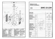
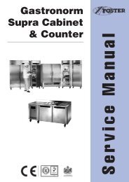
Wiring Diagram for High Temperature Models<br />
17
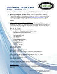
Wiring Diagram for Meat and Low Temperature Models<br />
18
<strong>Foster</strong> European Operations<br />
France<br />
<strong>Foster</strong> Refrigerator France SA<br />
Tel: (33) 01 34 30 22 22. Fax: (33) 01 30 37 68 74.<br />
Email: commercial@fosterfrance.com<br />
Germany<br />
<strong>Foster</strong> Refrigerator Gmbh,<br />
Tel: (49) 781 990 7840. Fax (49) 781 990 7844.<br />
Email: info@foster-gmbh.de<br />
<strong>Foster</strong> Refrigerator<br />
Oldmedow Road<br />
Kings Lynn<br />
Norfolk<br />
PE30 4JU<br />
Tel: 01553 691122<br />
Fax: 01553 691447<br />
Website: www.fosterrefrigerator.co.uk<br />
Email: sales@foster-uk.com<br />
a Division of ‘ITW (UK) Ltd’<br />
<strong>PRO</strong>’A’ LF28 CAB/COUNT/SM 03/08<br />
19