S9 Crane Runway Girder - Frilo
S9 Crane Runway Girder - Frilo
S9 Crane Runway Girder - Frilo

You also want an ePaper? Increase the reach of your titles
YUMPU automatically turns print PDFs into web optimized ePapers that Google loves.
Nemetschek <strong>Frilo</strong> GmbH - Applications for structural calculation and design<br />
<strong>S9</strong><br />
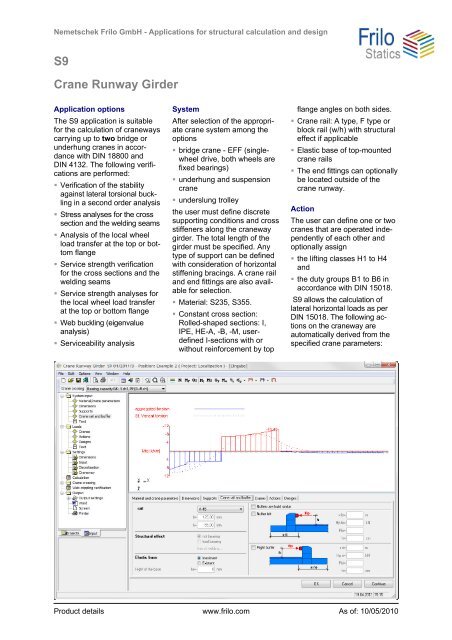
<strong>Crane</strong> <strong>Runway</strong> <strong>Girder</strong><br />
Application options<br />
The <strong>S9</strong> application is suitable<br />
for the calculation of craneways<br />
carrying up to two bridge or<br />
underhung cranes in accordance<br />
with DIN 18800 and<br />
DIN 4132. The following verifications<br />
are performed:<br />
Verification of the stability<br />
against lateral torsional buckling<br />
in a second order analysis<br />
Stress analyses for the cross<br />
section and the welding seams<br />
Analysis of the local wheel<br />
load transfer at the top or bottom<br />
flange<br />
Service strength verification<br />
for the cross sections and the<br />
welding seams<br />
Service strength analyses for<br />
the local wheel load transfer<br />
at the top or bottom flange<br />
Web buckling (eigenvalue<br />
analysis)<br />
Serviceability analysis<br />
System<br />
After selection of the appropriate<br />
crane system among the<br />
options<br />
bridge crane - EFF (singlewheel<br />
drive, both wheels are<br />
fixed bearings)<br />
underhung and suspension<br />
crane<br />
underslung trolley<br />
the user must define discrete<br />
supporting conditions and cross<br />
stiffeners along the craneway<br />
girder. The total length of the<br />
girder must be specified. Any<br />
type of support can be defined<br />
with consideration of horizontal<br />
stiffening bracings. A crane rail<br />
and end fittings are also available<br />
for selection.<br />
Material: S235, S355.<br />
Constant cross section:<br />
Rolled-shaped sections: I,<br />
IPE, HE-A, -B, -M, userdefined<br />
I-sections with or<br />
without reinforcement by top<br />
flange angles on both sides.<br />
<strong>Crane</strong> rail: A type, F type or<br />
block rail (w/h) with structural<br />
effect if applicable<br />
Elastic base of top-mounted<br />
crane rails<br />
The end fittings can optionally<br />
be located outside of the<br />
crane runway.<br />
Action<br />
The user can define one or two<br />
cranes that are operated independently<br />
of each other and<br />
optionally assign<br />
the lifting classes H1 to H4<br />
and<br />
the duty groups B1 to B6 in<br />
accordance with DIN 15018.<br />
<strong>S9</strong> allows the calculation of<br />
lateral horizontal loads as per<br />
DIN 15018. The following actions<br />
on the craneway are<br />
automatically derived from the<br />
specified crane parameters:<br />
Product details www.frilo.com As of: 10/05/2010
Self-weight<br />
Vertical wheel loads<br />
(with HM, if applicable)<br />
Horizontal lateral loads<br />
For standard systems, the<br />
loads are generated automatically.<br />
In special cases, the user<br />
can enter the loads that produce<br />
the actions directly.<br />
Therefore, the system is not<br />
limited to particular crane systems<br />
and other variable loads<br />
can be defined.<br />
The bumper forces are assessed<br />
by <strong>S9</strong>. Forces produced<br />
by start-up and braking operations<br />
of the crane bridge are not<br />
considered in the present software<br />
version.<br />
The combinations of actions<br />
are generated automatically.<br />
The user can take corrective<br />
actions directly here too. Predeformation<br />
is taken into account<br />
in accordance with the<br />
horizontal supporting conditions<br />
right from the beginning.<br />
Types of verifications<br />
Calculation of internal forces,<br />
deformations and stresses<br />
with imperfections in accordance<br />
with the second order<br />
bending torsion theory including<br />
warping torsion.<br />
Automatic assessment of the<br />
most unfavourable load positions<br />
for each verification<br />
Design as per DIN 18800 P1,<br />
P2, P3 and 4132:<br />
Verification of the ultimate<br />
limit states (e-e method) and<br />
the serviceability limit states<br />
Verification of the service<br />
strength as per DIN 4132<br />
Calculation of the stresses<br />
produced by the global supporting<br />
effects and the local<br />
loading resulting from load<br />
application<br />
Calculation of the design<br />
bearing forces, the bearing<br />
forces with a reduced dynamic<br />
coefficient or without<br />
such coefficient for the connected<br />
or foundation structures.<br />
Optionally, the user can take<br />
the mass forces HM and HS<br />
into account for one crane<br />
only or assign common MaxR<br />
and HM values to both cranes.<br />
Limitations<br />
Only the structural steels<br />
S235 and S355 are available.<br />
The reduction of fy,k when t ><br />
4 cm is not taken into account<br />
Constant cross section<br />
No hollow boxes<br />
The user might be required to<br />
adjust the pre-deformation<br />
produced by the decisive action<br />
subsequently<br />
Output<br />
Additional output sections<br />
showing particular calculation<br />
results<br />
Variable output profile optionally<br />
structured according to<br />
the system, the loads, the<br />
general structural safety verifications<br />
or special verifications<br />
of the craneway<br />
3-dimensional graphical representation<br />
of the results of<br />
each superposition for the<br />
structural safety, the serviceability<br />
and the service<br />
strength<br />
Graphical representation of<br />
the limit line of the internal<br />
forces Qz, My, Qy, Mz, Mt<br />
and Mw<br />
Optional bar graph of axial,<br />
shear and comparison<br />
stresses in each relevant<br />
point of the cross section over<br />
the entire craneway girder per<br />
mouse click<br />
Optional graphical representation<br />
of the service strength<br />
verifications per notch case at<br />
each point of the cross section<br />
over the entire craneway<br />
girder per mouse click<br />
If the PLII application is installed,<br />
the user can transfer<br />
the system and the loading<br />
for the verification of the web<br />
buckling stability<br />
Enhanced web buckling examinations<br />
Buckling safety verifications are<br />
always required for craneway<br />
girders. The safety against<br />
buckling failure must be verified<br />
for webs and compression<br />
flanges. The verification of the<br />
buckling safety of compression<br />
flanges is typically done by<br />
verifying the limit ratio of b/t in<br />
accordance with DIN 18800-1,<br />
Tab. 13. Where rolled sections<br />
are concerned, this verification<br />
produces a positive result under<br />
normal conditions. Because<br />
web buckling must be examined<br />
under simultaneous action<br />
of the edge stresses x, y and<br />
, a simplified verification of the<br />
buckling safety as per<br />
DIN 18800-1, merely checking<br />
compliance with the limit b/t<br />
ratio, is not suitable.<br />
In <strong>S9</strong>, the basic combination of<br />
permanent actions and vertical<br />
wheel loads is taken into account<br />
as the largest variable<br />
action in the verification of the<br />
safety against web buckling.<br />
This verification is limited to the<br />
web buckling safety under<br />
wheel loads in the span of the<br />
girder. Under particular conditions,<br />
additional examinations<br />
of the web buckling behaviour<br />
might be required. The application<br />
PLII Plate Buckling is<br />
available for this task. <strong>S9</strong> offers<br />
a corresponding interface to<br />
PLII for the data transfer.