FDS Strip Foundation - Frilo
FDS Strip Foundation - Frilo
FDS Strip Foundation - Frilo

You also want an ePaper? Increase the reach of your titles
YUMPU automatically turns print PDFs into web optimized ePapers that Google loves.
Nemetschek <strong>Frilo</strong> GmbH - Applications for structural calculation and design<br />
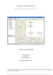
<strong>FDS</strong><br />
<strong>Strip</strong> <strong>Foundation</strong><br />
The <strong>FDS</strong> application allows you<br />
to calculate the required dimensions<br />
of strip foundations<br />
under centric and uniaxial eccentric<br />
loading. The required<br />
bending and shear reinforcement<br />
is calculated for the selected<br />
dimensions.<br />
Standards<br />
DIN EN 1992<br />
ÖNORM EN 1992<br />
BS EN 1992<br />
DIN 1045/1045-1<br />
ÖNorm B4700<br />
Soil standard:<br />
DIN EN 1997-1 in<br />
conjunction with<br />
DIN 1054:2010.<br />
ÖNORM EN 1997-1 in<br />
conjunction with<br />
DIN 1054:2005.<br />
Depending on the selected<br />
concrete standard the<br />
appropriate soil standard is<br />
selected automatically<br />
(DIN 1054:1976/2005/2010).<br />
Loads<br />
Wind loads G and Q<br />
Moments MG and Mq<br />
Loading on the foundation<br />
area left and/or right to the<br />
wall<br />
The self-weight of the foundation<br />
is considered automatically.<br />
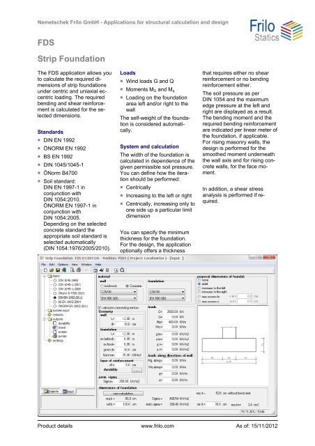
System and calculation<br />
The width of the foundation is<br />
calculated in dependence of the<br />
given permissible soil pressure.<br />
You can define how the iteration<br />
should be performed:<br />
Centrically<br />
Increasing to the left or right<br />
Centrically, increasing only to<br />
one side up a particular limit<br />
dimension<br />
You can specify the minimum<br />
thickness for the foundation.<br />
For the design, the application<br />
optionally offers a thickness<br />
that requires either no shear<br />
reinforcement or no bending<br />
reinforcement either.<br />
The soil pressure as per<br />
DIN 1054 and the maximum<br />
edge pressure at the left and<br />
right are displayed as a result.<br />
The bending moment and the<br />
required bending reinforcement<br />
are indicated per linear meter of<br />
the foundation, if applicable.<br />
For rising masonry walls, the<br />
design is performed for the<br />
smoothed moment underneath<br />
the wall axis and for rising concrete<br />
walls, for the face moment.<br />
In addition, a shear stress<br />
analysis is performed if required.<br />
Product details www.frilo.com As of: 15/11/2012
Optionally, you can design the<br />
connecting reinforcement for<br />
rising concrete walls.<br />
Under permanent load, no gaping<br />
joint must occur and under<br />
the total load, gaping of the<br />
foundation joint is only allowed<br />
up to the centre of gravity.<br />
The permissible soil pressure<br />
refers to a partial surface A'<br />
with the load application point<br />
in its center.<br />
The bending design is performed<br />
in accordance with the<br />
kh-method. The design moment<br />
for the bending design is calculated<br />
in the wall axis with masonry<br />
walls and at the face with<br />
concrete walls.<br />
The shear reinforcement is<br />
located at a distance equal to<br />
h/2 from the left and right wall<br />
edge. Outputs are:<br />
the shear force at the design<br />
section, Tau0,<br />
Tau (including the shear<br />
zone-specific reduction) and<br />
the shear reinforcement resulting<br />
from Tau.<br />
According to DIN 1045, no<br />
shear reinforcement is required<br />
if the following applies:<br />
max Tau0 < k1 . Tau0ll