Future Technology Devices International Ltd. FT120 - FTDI
Future Technology Devices International Ltd. FT120 - FTDI
Future Technology Devices International Ltd. FT120 - FTDI

Create successful ePaper yourself
Turn your PDF publications into a flip-book with our unique Google optimized e-Paper software.
Document No.: FT_000646<br />
<strong>FT120</strong> USB DEVICE CONTROLLER WITH PARALLEL BUS IC<br />
Datasheet Version 1.0<br />
Clearance No.: <strong>FTDI</strong># 291<br />
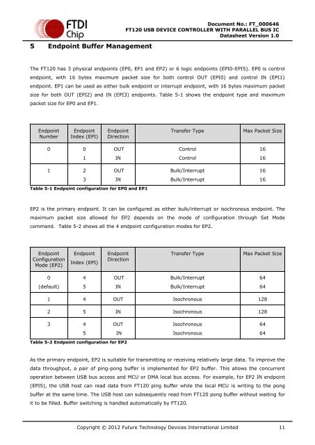
5 Endpoint Buffer Management<br />
The <strong>FT120</strong> has 3 physical endpoints (EP0, EP1 and EP2) or 6 logic endpoints (EPI0-EPI5). EP0 is control<br />
endpoint, with 16 bytes maximum packet size for both control OUT (EPI0) and control IN (EPI1)<br />
endpoint. EP1 can be used as either bulk endpoint or interrupt endpoint, with 16 bytes maximum packet<br />
size for both OUT (EPI2) and IN (EPI3) endpoints. Table 5-1 shows the endpoint type and maximum<br />
packet size for EP0 and EP1.<br />
Endpoint<br />
Number<br />
0<br />
1<br />
Endpoint<br />
Index (EPI)<br />
0<br />
1<br />
2<br />
3<br />
Endpoint<br />
Direction<br />
OUT<br />
IN<br />
OUT<br />
Table 5-1 Endpoint configuration for EP0 and EP1<br />
IN<br />
Transfer Type Max Packet Size<br />
Control<br />
Control<br />
Bulk/Interrupt<br />
Bulk/Interrupt<br />
EP2 is the primary endpoint. It can be configured as either bulk/interrupt or isochronous endpoint. The<br />
maximum packet size allowed for EP2 depends on the mode of configuration through Set Mode<br />
command. Table 5-2 shows all the 4 endpoint configuration modes for EP2.<br />
Endpoint<br />
Configuration<br />
Mode (EP2)<br />
0<br />
(default)<br />
Endpoint<br />
Index (EPI)<br />
4<br />
5<br />
Endpoint<br />
Direction<br />
OUT<br />
IN<br />
Copyright © 2012 <strong>Future</strong> <strong>Technology</strong> <strong>Devices</strong> <strong>International</strong> Limited 11<br />
16<br />
16<br />
16<br />
16<br />
Transfer Type Max Packet Size<br />
Bulk/Interrupt<br />
Bulk/Interrupt<br />
1 4 OUT Isochronous 128<br />
2 5 IN Isochronous 128<br />
3 4<br />
5<br />
OUT<br />
IN<br />
Table 5-2 Endpoint configuration for EP2<br />
Isochronous<br />
Isochronous<br />
As the primary endpoint, EP2 is suitable for transmitting or receiving relatively large data. To improve the<br />
data throughput, a pair of ping-pong buffer is implemented for EP2 buffer. This allows the concurrent<br />
operation between USB bus access and MCU or DMA local bus access. For example, for EP2 IN endpoint<br />
(EPI5), the USB host can read data from <strong>FT120</strong> ping buffer while the local MCU is writing to the pong<br />
buffer at the same time. The USB host can subsequently read from <strong>FT120</strong> pong buffer without waiting for<br />
it to be filled. Buffer switching is handled automatically by <strong>FT120</strong>.<br />
64<br />
64<br />
64<br />
64