White paper - MathWorks
White paper - MathWorks
White paper - MathWorks

Create successful ePaper yourself
Turn your PDF publications into a flip-book with our unique Google optimized e-Paper software.
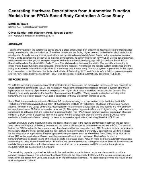
Generating Hardware Descriptions from Automotive Function<br />
Models for an FPGA-Based Body Controller: A Case Study<br />
Matthias Traub<br />
Daimler AG, Research & Development<br />
Oliver Sander, Arik Rathner, Prof. Jürgen Becker<br />
ITIV, Karlsruhe Institute of Technology (KIT)<br />
ABSTRACT<br />
Today's innovations in the automotive sector are, to a great extent, based on electronics. New features are often realized<br />
solely on embedded electronic devices. Therefore, developers are facing higher demand in the field of electric/electronic<br />
architecture. Actually more and more applications are developed using Model-Based Design in the automotive domain.<br />
While C code generation is already used in series development, no satisfying solution for VHDL or Verilog generation was<br />
available on the market yet, for example, to generate hardware description language (HDL) code from Simulink® or<br />
Stateflow® models. Simulink® HDL Coder from The <strong>MathWorks</strong> introduces this ability. The tool offers the ability to<br />
divide model-based functions into hardware- and software-modules. Advantages are flexible system partitioning and the<br />
ability to accelerate time-critical applications in a hardware unit. A case study for such a system is presented in this <strong>paper</strong>.<br />
In a cooperation project between the Karlsruhe Institute of Technology (KIT) and Daimler AG, a field programmable gate<br />
array (FPGA)–based body controller unit (BCU) was developed, including automatically generated HDL code.<br />
INTRODUCTION<br />
To fulfill the increasing requirements of electric/electronic architectures in the automotive environment, new concepts for<br />
future electronic control units (ECUs) are necessary. Novel semiconductor technologies for such a system offer much<br />
higher potential in terms of performance compared with higher clock rates in standard microcontroller devices. The<br />
following case study introduces the benefits of a new concept for a BCU. The system is realized on reconfigurable<br />
hardware, more precisely on an FPGA, and is integrated in the SL-Class from Mercedes-Benz.<br />
Since 2001 the research department of Daimler AG has been working on a cooperation project with the Institut für<br />
Technik der Informationsverarbeitung (ITIV) at the Karlsruhe Institute of Technology. The focus of this project has two<br />
aspects. The first is the usage of dynamic reconfiguration for automotive applications [1]. The second is a new gateway<br />
concept based on an FPGA for automotive networks [2]. This system approach offers much higher routing performance in<br />
comparison to gateways that are realized on a microcontroller. The FPGA-based gateway concept is also part of a case<br />
study for a BCU, which is discussed later in this <strong>paper</strong>. For the applications that are running on the BCU, we have<br />
evaluated a hardware/software codesign process for automotive applications, including Simulink HDL Coder.<br />
Current and future BCUs must fulfill mainly two tasks. The first task is the routing of information between the controller<br />
area network (CAN) bus of the body domain and the several LIN subbuses that are connected to the BCU. The second<br />
task of the BCU is to handle the huge amount of applications that are integrated on it. BCU functions include, for example,<br />
the window lifter, the mirror control, and the front light, to name only a few. For our BCU approach we use two methods<br />
for the integration of applications. First we apply softcore processors such as MicroBlaze from Xilinx [16] or Nios2 from<br />
Altera [17] for the applications. Second we integrate several functions in hardware. The toolflow for such a<br />
hardware/software codesign is one of the main aspects in our case study. Actually, more and more automotive functions<br />
are developed using Model-Based Design. Therefore, we use the embedded code generation of Simulink for our function<br />
models. We generate C code for the software modules that run on a processor and HDL code for the application<br />
modules, which are accelerated in hardware.<br />
The remaining <strong>paper</strong> is organized as follows: In the next section some technical basics are discussed to provide a<br />
common comprehension. The subsequent section introduces the case study. It starts with the system concept, gives an<br />
overview of the design flow used, and discusses an implementation example. The last section provides the results of the<br />
work and gives an outlook.
NETWORK ARCHITECTURE<br />
Today up to 80 ECUs are used in premium cars. In order to guarantee reliable communication between them, complex<br />
networks are necessary. Actual automotive network architectures partition the ECUs into different domains depending on<br />
their functionality (body, chassis, powertrain, infotainment, etc.). For the requirements of the different domains, several<br />
protocols are available. The CAN bus protocol is primarily used for inter-ECU communication. It is an event-driven<br />
multimaster protocol that is not deterministic [11]. The main fields of application for CAN are the body, chassis, and<br />
powertrain domains. Local Interconnect Network (LIN) is a low-cost protocol used for communication among simple<br />
modules such as switch panels [12]. It is deterministic and easy to implement but features low speed only. FlexRay is the<br />
youngest communication standard for automotive networks. It consists of a deterministic and nondeterministic part. It<br />
offers higher throughput compared with CAN and is designed for X-by-wire and backbone applications [13]. Media<br />
Oriented System Transport (MOST) is a communication protocol used for infotainment devices [14]. Additionally Ethernet<br />
will become the diagnostic entrance to the car in the future [15].<br />
FIELD PROGRAMMABLE GATE ARRAY<br />
Reconfigurable hardware such as FPGAs offers many advantages in comparison to fixed architectures. A single device<br />
can be used for numerous and very different tasks by adapting the hardware to the task during design, and even during<br />
runtime. It is very suitable for rapid prototyping but also for limited-lot production of systems if the design of an ASIC is too<br />
expensive or time-consuming. Quite a few reconfigurable hardware platforms are available (for example, Cypress's PSoC<br />
Mixed-Signal Array, Actel Fusion, CPLD, FPGA).<br />
An FPGA is a semiconductor containing programmable logic components called configurable logic blocks (CLBs) as well<br />
as programmable interconnects. The logic function of the block is implemented using look-up tables (LUTs). These are<br />
one-bit-wide memories whose inputs are interpreted as address lines. The one-bit content of the addressed memory is<br />
used as the LUT's output. Thus the CLBs can be programmed to perform any combinatorial function by loading the<br />
appropriate values in the LUT's memory addresses — only constrained by the CLB's number of inputs and outputs.<br />
Through programmable interconnects, so-called switchboxes, CLBs can be interconnected to form very complex digital<br />
circuits and designs. In data-driven applications FPGAs are therefore able to heavily parallelize tasks, thus speeding up<br />
an application substantially. By including a softcore processor, functions can still be carried out in software. At the same<br />
time it is possible to partition functions over software and hardware to exploit the distinct advantages of both and build<br />
complete digital systems-on-chip (SoCs) including functional blocks and their communication infrastructure such as buses<br />
or complete networks-on-chip (NoCs). Configuring FPGAs is done by writing a bitstream to the device over a<br />
programming interface, for example, the JTAG. The LUTs are loaded with appropriate values and the switchboxes are<br />
programmed. Most of the FPGAs are SRAM based (for example, from Xilinx); therefore, loading a bitstream is mandatory<br />
after every power-up in order to have a working system. The bitstreams are usually stored in external flash memory. In<br />
newer devices, memory has been integrated into the FPGA's package, decreasing the need for external memory<br />
components. A bitstream is loaded into the device, initializing the FPGA's look-up tables, internal memory blocks, and<br />
switchboxes to form the chip's digital functionalities.<br />
SIMULINK HDL CODER<br />
Simulink HDL Coder offers the ability to generate synthesizable HDL code from Simulink models and Stateflow charts<br />
[10]. The generated HDL code is target independent. On this account, the generated code can be mapped on an FPGA or<br />
an application-specific integrated circuit (ASIC). Furthermore, Simulink HDL Coder generates test benches, which enable<br />
rapid verification of the generated model using HDL simulation tools such as ModelSim from Mentor Graphics [9].<br />
CASE STUDY<br />
One trend for network architectures in the automotive field is the use of powerful ECUs to realize high function integration.<br />
The main benefits are a reduction of the number of ECUs and better system integration. The BCU of the body domain is<br />
one example (see Figure 1). With the introduction of the LIN bus, new function integration and partitioning are possible.<br />
Figure 1. Actual trend, for example, in the body domain.
In our case study we built such a BCU concept. Based on the network architecture of an existing car, we changed the<br />
partitioning of the architecture. In our project we focused on a part of the comfort domain. The reduction of ECUs was one<br />
main aspect. Another issue was the use of an FPGA as the central computing unit for the BCU prototype. Therefore, we<br />
faced questions of hardware/software codesign for model-based functions. The system example was integrated in the SL-<br />
Class from Mercedes-Benz (DATE). The key aspects of our case study are to find out and understand the necessary<br />
design flow for such systems and to identify differences for the development and qualification process between a<br />
microcontroller and an FPGA-based ECU.<br />
SYSTEM CONCEPT<br />
System partitioning is done on two abstraction levels. First, we define the overall system architecture. Second,<br />
hardware/software partitioning for the central body controller is made. All decisions are based on a functional analysis of<br />
all user-related functions we want to exchange. In principle all body-domain-related functions should run in the BCU. No<br />
additional ECUs are necessary despite small intelligent sensor and actuator modules that communicate with the BCU via<br />
the low-cost LIN bus. In fact we restricted ourselves to a selection of functions, normally located in the door modules and<br />
the roof control ECU. The former are removed from the car; the latter is running in a special mode. The functions of the<br />
removed CAN ECU are implemented in our concept on the BCU. In addition routing between our novel architecture and<br />
the other domains must be handled by the BCU.<br />
The overall function distribution is based on the architecture shown in Figure 2. Two CAN and four LIN buses are<br />
attached to our BCU prototype. The first CAN bus is the existing body CAN, which is the interface to the remaining<br />
electronic architecture of the car. We introduced four LIN buses for our smart sensor and actuator modules. Two of these<br />
buses wired to the front doors with two LIN slaves in each door. The remaining two buses are attached to the rear power<br />
window devices. Of course, fewer LIN buses would be sufficient. However, we decided to demonstrate modularity and the<br />
ability of our FPGA system architecture to run several buses in parallel. To save time we did not realize the analog LIN<br />
interfacing to the roof components on our own. This is the reason a second CAN bus is connected to a special version of<br />
the roof control ECU. This special ECU allows controlling actuators and reading sensors via CAN bus over diagnostic<br />
messages.<br />
Figure 2. System concept.<br />
In general we tried to concentrate as much functionality as possible in the central FPGA system. Only low-level functions<br />
such as debouncing are integrated in the local LIN modules. The antipinch protection of the window lifter is the only<br />
exception. This function is integrated in the LIN slaves. The reason for this partitioning is the performance of the LIN bus,<br />
which does not fulfill the required latency time.<br />
The system demonstrates how standardized sensor and actuator modules could look. The modules used in our project<br />
are a development of Siemens VDO. Moreover, this concept introduces a possible system partitioning approach for<br />
applications in the body domain. Low-level functions, which are application independent, and a standardized bus interface<br />
are integrated in the sensor or actuator module. All these functions can be attached in one single package that probably<br />
builds a small SoC. All application-specific functions are implemented on the BCU. The LIN modules can be used as<br />
convertible standard components possibly delivered by different suppliers. These components can be set up for the<br />
application by parameterization. On the BCU side the interface to the physical world is quite simple because no low-level<br />
functions or analog parts are necessary. Information exchange is based on message transport level via LIN or other bus<br />
systems.
As already mentioned the roof control is the most important function in our system approach, running on the BCU.<br />
Moreover, some higher-level power window control functions are integrated. This includes switch prioritization as well as<br />
monitoring of system conditions (for example, clamp 15). Power management for the LIN nodes is also implicitly done in<br />
the BCU. When scheduling is stopped, the LIN modules fall asleep after a given time. The BCU is master for all LIN<br />
buses. We have integrated parts of the seat control because the control buttons are placed inside the door. The seat<br />
control itself is not realized in our system. Furthermore, the mirror control function runs in the BCU. Some routing tasks<br />
are also realized in the BCU.<br />
The basis for the BCU is an FPGA-based gateway system, which we have already developed within another project. The<br />
evaluation board for the BCU has four CAN and four LIN interfaces. The FPGA is a Spartan3 XC 3S5000 from Xilinx.<br />
Siemens VDO designed the LIN modules for this case study.<br />
Most functionality is integrated in a softcore processor. To evaluate hardware toolflows we decided to test two<br />
implementations of the roof control functionality. The functionality is modeled in MATLAB®, Stateflow, and Simulink. In<br />
our first version, software code was generated and integrated into the softcore processor. Our second version is realized<br />
in hardware. The roof control function runs in parallel to all remaining functions, thereby not influencing other tasks. The<br />
hardware model is also generated from the MATLAB model. The toolflows we used will be described later on. The<br />
interface to our internal communication system has to be done by hand. However, the generated model was not changed<br />
and its behavior is equivalent to that of the model and the software version. In fact we can switch between both<br />
realizations.<br />
Figure 3 shows an abstract overview of our system approach. The system is built by plugging several modules together.<br />
This flexibility is mainly achieved by the central communication structure and a well-defined interface. Four functional<br />
parts can be seen in Figure 3. On the bottom are the bus interfaces to CAN, LIN, and USB. We used USB for debugging<br />
and flashing purposes only. On the upper left is the roof control function, which can be split into three parts (roll bar<br />
control, load help control, and convertible top control). The upper central element is the softcore processor, which runs all<br />
the software applications. In our approach we use a MicroBlaze processor from Xilinx as the softcore processor. The<br />
modules on the upper right are responsible for fast and efficient routing [2].<br />
Figure 3. FPGA-based body controller.<br />
Communication Structure<br />
The communication between the individual modules of the BCU is of paramount importance for the overall system<br />
performance. We decided not to implement a memory-mapped address-based communication structure. In this<br />
application a very simple network on chip (GNoC) approach was used. It is a combination of a bus topology with network<br />
packets being sent. All modules are equal and can receive and send data packets independently. Mechanisms for<br />
broadcast and unicast exist. Our communication structure supports easy adding and removing of modules.<br />
Bus Interfaces<br />
The bus interfaces include the protocol engines as well as low-level bus-related functionality. For example, the bus off<br />
repair procedure of the CAN bus is processed without affecting other modules. We implemented interfaces for CAN, LIN,<br />
FlexRay, and Ethernet; the latter are not a topic of this case study. These transferred messages are buffered in the<br />
modules. The operation mode of the system does not depend on the bus type. The messages that have been received
are broadcast to the internal communication network. The messages, which have to be sent to the attached buses, are<br />
received from the internal communication structure. The internal forwarding of the information on the bus happens as fast<br />
as possible.<br />
Message RAM and Routing Engine Modules<br />
In our system approach, two modules process all gateway routing tasks. The Message RAM module forwards messagerouting<br />
messages and sends all signal-routing messages. Cycle times as well as timeout handling are controlled by this<br />
module. Despite timeout values the data fields are not altered by the Message RAM module. Whenever the content of a<br />
message needs to be changed, for example in case of a signal-routing or bus conversion, another module, the Routing<br />
Engine module, is involved. The main task of the Routing Engine module is to group several signals from many messages<br />
into a new message. Signals are concatenated with hardware support with the new data field as a result. Further<br />
processing is done by the Message RAM, which takes care of all messages’ behavior (cycle times, timeout values, etc.).<br />
Processor System<br />
All parts of the software stack with the exception of the bus drivers and gateway functionality are implemented in the<br />
application module. The main part of the module is a softcore processor (see Figure 4). We use the MicroBlaze processor<br />
from Xilinx and some peripheral elements. In our application a timer, the NoC interface, a UART peripheral (debugging),<br />
and the memories are attached to the processor. We decided to use a simple runtime system instead of a complex OSEK<br />
version for availability reasons. The runtime system implements no preemption. Tasks are called in certain time slots, and<br />
each of them ensures running within the allotted time. If a message is received, the corresponding signal values are<br />
immediately updated by an ISR. Incoming signal values are available for all tasks. We have the following tasks running:<br />
window lifter, seat control, switch prioritization, and roof control (in our software version). The latter includes some<br />
managing tasks of our special roof control ECU. If the hardware implementation is used, the roof control forwards all<br />
controlling signals directly to the hardware implementation.<br />
Figure 4. Softcore processor system.<br />
Hardware Module<br />
The hardware implementation of the roof control is mainly based on the generated VHDL code of the roof control. The<br />
entire hardware module is shown in Figure 5. Of course, the behavior of the system should be the same as that of the<br />
C code version. This was ensured by simulation comparing the output signals for given test cases. As the hardware is<br />
running much faster than the software version, timeout values are extremely different (a factor of 24k). To overcome this<br />
resource-consuming implementation, the model is simply executed less often. As the timer values are originally defined<br />
for the software version in terms of milliseconds, we decided to do a mixture of executing the model less often and<br />
adapting the timeout values of the original model.<br />
Inputs and outputs of the VHDL model are the same as in the software version. These fit neither directly to the MicroBlaze<br />
processor system nor to our internal communication structure. We implemented an interface for the second variant. We<br />
chose this version for two reasons. First, the function can run processor independent, thus reducing the workload of the<br />
processor. Second, the module can easily be added or removed from the internal communication structure without
affecting the other modules. Moreover, the GNoC has a well-defined interface that allows independent testing of the<br />
module.<br />
Figure 5. Hardware module.<br />
Attaching the VHDL model to the GNoC is mainly done by a very small 8-bit processor core (PicoBlaze) not comparable<br />
to 8-bit microcontrollers. The decision for this solution is based on its resource efficiency and flexibility while providing<br />
enough computational performance for the glue logic task. Incoming NoC packets are filtered. The information is targeted<br />
to the roof control function and stored in a special register file. This is read by the hardware task the next time it is<br />
executed. Outgoing information is also transmitted to our small processor. The processor packs the information into<br />
GNoC packages, which will be transmitted to the internal network. Depending on the information, the message is further<br />
processed by the routing modules or in special cases by the application module.<br />
DESIGN FLOW<br />
Identifying and understanding the necessary design flow for an FPGA-based BCU was one main aspect of our case<br />
study. The established design flow for microcontrollers comprises the process for software components. The use of the<br />
FPGA technology requires an extension of the existing design flow. To fulfill these needs, a hardware/software codesign<br />
process must be introduced. A seamless design flow is very important for the development of automotive systems. The<br />
identification and the definition of the interfacing of the different tools must be clear; otherwise, the launch of FPGA-based<br />
systems in the automotive domain is improbable.<br />
Figure 6 shows the design flow used for our system approach. The design process is divided into three paths. The first<br />
path on the left side of the diagram contains the generation of the routing tables for the hardware-accelerated routing unit.<br />
The software part is built in the second path. This part contains the basis software modules (for example, operating<br />
system, system drivers, network management) and the software modules of the application. The right path comprises the<br />
hardware system. Parts of it are the softcore processor, the chip internal communication structure, the bus interfaces, the<br />
routing unit, and the generated application modules.<br />
Most of the applications for the BCU are modeled with Simulink and Stateflow. The software or hardware modules can be<br />
generated by means of code generation, which is part of Simulink. Afterward, the generated modules can be integrated,<br />
depending on their type, in the software or hardware development environment (DEV). The software modules (in C code)<br />
must be integrated on the softcore processor; in our example, it is a 32-bit MicroBlaze processor from Xilinx. The<br />
integration process for the software modules is well known because there is no difference to the design flow for<br />
microcontroller-based systems.<br />
For the automatically generated hardware modules of the applications, the integration process is not established yet in<br />
the automotive field. In our project we have done the design of the hardware part as follows: In the first step the softcore<br />
processor system is built. In the next step this system is coupled with a generic interface of the internal communication<br />
structure. In the hardware DEV the entire system must be integrated, which includes the processor system as well as the
outing unit, the communication interfaces, the internal communication structure, and the hardware application modules,<br />
which are provided by a special library. In the last step the hardware system can be synthesized.<br />
Figure 6. Design flow.<br />
IMPLEMENTATION EXAMPLE<br />
In our case study we have evaluated different approaches for the integration of applications on the BCU. In the first<br />
approach we integrated the entire functionality in software on the softcore processor. In the second approach a part of the<br />
application is implemented in hardware. Among others, this was done for the convertible roof control, which is described<br />
in this section. The demonstration car was from the SL-Class from Mercedes-Benz and has an electrohydraulic roof. The<br />
top opens and closes within 20 seconds. Twelve switches act as sensors for the top control. The actors are seven<br />
hydraulic valves, which are coupled at one pump. The simplified Simulink model of the roof control is shown in Figure 7.<br />
In one variant of our system the top control is integrated on the softcore processor. In a second variant the top control is<br />
realized as a hardware module. Table 1 shows the necessary hardware and memory resources for this module (the<br />
results are based on a Spartan3 FGPA of Xilinx). The hardware module is generated with Simulink HDL Coder from The<br />
<strong>MathWorks</strong> and synthesized with Integrated System Environment (ISE) software from Xilinx. The module needs 1161<br />
slices on a Spartan3 FPGA from Xilinx. In comparison to the size of the MicroBlaze 32-bit softcore processor, which<br />
allocates about 700 slices, the hardware module of the roof control is inefficient in hardware. We got this result with most<br />
of the application modules. However, the use of automatically generated hardware models has some benefits. The<br />
modules run in parallel and do not influence each other. Moreover, a hardware implementation offers much more<br />
computational power, which can be useful for tasks with high computational demands (for example, multimedia). The<br />
given performance can also be used for ECU prototyping purposes.
Figure 7. Simplified model for the convertible top control.<br />
Hardware Module<br />
(Slices)<br />
Software Module<br />
(KB)<br />
Convertible top function 1162 3.552<br />
Table 1. Comparison of hardware and software realization of the roof control.<br />
In general, the control-flow-based functions need a lot of logic elements in hardware. Therefore, the realization of the<br />
application modules in software is the better way. For functions that must handle a high data volume (for example,<br />
gateway systems or video processing units), a hardware realization can be very performant and resource-efficient.<br />
Examples of such a hardware acceleration unit are the routing modules of our system approach. For CAN-CAN message<br />
routing, the systems needs about 8 ms at a system clock of 24 MHz; compared with a software-based solution (120ms at<br />
80 MHz), the performance benefit of such a system is significant.<br />
CONCLUSION<br />
In current and future electric/electronic architectures, the integration of applications on powerful ECUs is a trend. These<br />
powerful computing units offer the opportunity to reduce the number of ECUs inside a car. Furthermore, the high<br />
computing power enables the possibility to integrate new innovations of automotive applications. The usage of<br />
reconfigurable hardware gives an interesting alternative to the well-known microcontroller-based solutions. A modular<br />
body controller prototype based on FPGA technology was developed and realized in this case study. The prototype<br />
utilizes the advantages of this technology such as parallelism and modularity. The main focus of the project, namely the<br />
integration of several functions on one powerful computing unit and usage of Model-Based Design, is presented in this<br />
<strong>paper</strong>. Our future work will focus on open questions regarding qualification, toolflow, and the evaluation of the FPGA<br />
technology for integration in AUTOSAR.<br />
REFERENCES<br />
1. J. Eisenmann, J. Luka (Daimler AG), J. Becker, M. Hübner (Karlsruhe Institute of Technology); “Dynamic<br />
reconfiguration for automotive applications”; Design Automation and Test in Europe (DATE) Conference 2005 in<br />
Munich<br />
2. O. Sander, M. Hübner, M. Dreschmann, J. Becker (Karlsruhe Institute of Technology), M. Traub, J. Luka, T. Weber<br />
(Daimler AG); “Modular system concept for a FPGA-based Automotive Gateway”; Elektronik im Kraftfahrzeug, VDI-<br />
Conference 2007 in Baden-Baden<br />
3. J. Eisenmann, J. Luka (Daimler AG); “FPGA-based Electronic Control Units for Comfort Systems in Vehicle”; Design<br />
Automation and Test in Europe Conference 2006 in Munich<br />
4. M. Traub, J. Luka, V. Lauer, T. Weber (Daimler AG), O. Sander, M. Hübner, Prof. Becker (KIT); “Standards for<br />
Electric/Electronic Components and Architectures”; to be published at Convergence 2008 in Detroit<br />
5. Arik Rathner (KIT); “Approach for a FPGA-based BCU”; seminar <strong>paper</strong> 2007<br />
6. www.mathworks.com<br />
7. www.xilinx.com<br />
8. www.autosar.org<br />
9. Mentor Graphics; “User Handbook for ModelSim”; Version 6.0, 2007<br />
10. The <strong>MathWorks</strong>; “Simulink HDL Coder User’s Guide”; 2007<br />
11. Robert Bosch GmbH; “Controller Area Network Specification”; Version 2.0, 1991<br />
12. “Local Interconnect Network Specification”; Revision 2.0, 2003<br />
13. “FlexRay Communication System, Protocol Specification”; v2.1, Rev. A, 2006<br />
14. MOST Cooperation; “Media Oriented System Transport Specification”; Rev. 4, 05/2005<br />
15. Bernd Schürmann; “Grundlagen der Rechnerkommunikation”; Vieweg Verlag, ISBN 3-528-15562-0, 2004<br />
16. Xilinx; “MicroBlaze Processor Reference Guide”; UG081 (v7.0), 2007<br />
17. Altera; “Nios II Processor Reference Handbook”; NII5V1-6.1, 2007