Grasso Screw compressors Types C ... XF Product Information - GEA ...
Grasso Screw compressors Types C ... XF Product Information - GEA ...
Grasso Screw compressors Types C ... XF Product Information - GEA ...

You also want an ePaper? Increase the reach of your titles
YUMPU automatically turns print PDFs into web optimized ePapers that Google loves.
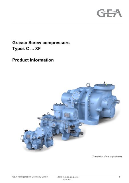
<strong>Grasso</strong> <strong>Screw</strong> <strong>compressors</strong><br />
<strong>Types</strong> C ... <strong>XF</strong><br />
<strong>Product</strong> <strong>Information</strong><br />
(Translation of the original text)<br />
<strong>GEA</strong> Refrigeration Germany GmbH _101011_pi_sc_gbr_2_.doc 1<br />
23.03.2012
PRODUCT INFORMATION<br />
GRASSO SCREW COMPRESSORS<br />
<strong>Types</strong> C ... <strong>XF</strong><br />
COPYRIGHT<br />
All Rights reserved.<br />
No part of this publication may be copied or published<br />
by means of printing, photocopying, microfilm<br />
or otherwise without prior written consent of<br />
• <strong>GEA</strong> Refrigeration Germany GmbH<br />
herein after called manufacturer. This restriction<br />
also applies to the corresponding drawings and diagrams.<br />
LEGAL NOTICE<br />
This documentation has been written in all conscience.<br />
However, the manufacturer cannot be held<br />
responsible, neither for any errors occurring in this<br />
documentation nor for their consequences.<br />
2 _101011_pi_sc_gbr_2_.doc <strong>GEA</strong> Refrigeration Germany GmbH<br />
23.03.2012
PRODUCT INFORMATION<br />
GRASSO SCREW COMPRESSORS<br />
<strong>Types</strong> C ... <strong>XF</strong><br />
SYMBOLS USED IN THIS MANUAL<br />
Danger!<br />
Stands for an immediate danger<br />
which leads to heavy physical injuries<br />
or to the death.<br />
Warning!<br />
Stands for a possibly dangerous situation<br />
which leads to heavy physical<br />
injuries or to the death.<br />
Caution!<br />
Stands for a possibly dangerous situation<br />
which could lead to light physical<br />
injuries or to damages to property.<br />
Hint!<br />
Stands for an important tip whose<br />
attention is important for the designated<br />
use and function of the device.<br />
<strong>GEA</strong> Refrigeration Germany GmbH _101011_pi_sc_gbr_2_.doc 3<br />
23.03.2012
PRODUCT INFORMATION<br />
GRASSO SCREW COMPRESSORS<br />
<strong>Types</strong> C ... <strong>XF</strong><br />
TABLE OF CONTENTS<br />
1 INTRODUCTION ............................................................................................................................ 8<br />
1.1 OPERATIONAL AREA ...................................................................................................... 8<br />
1.2 PRODUCT RANGE ........................................................................................................... 8<br />
1.3 TECHNICAL FEATURES ................................................................................................ 10<br />
2 PRODUCT OVERVIEW ............................................................................................................... 11<br />
3 COMPRESSOR DESCRIPTION .................................................................................................. 12<br />
3.1 <strong>Product</strong> description / <strong>Product</strong> code .................................................................................. 12<br />
4 COMPRESSOR DESIGN CRITERIA ........................................................................................... 17<br />
5 OPERATING LIMITS.................................................................................................................... 19<br />
6 MAIN DIMENSIONS..................................................................................................................... 24<br />
6.1 SERIES SH; TYPE C, D .................................................................................................. 24<br />
6.2 SERIES SH; TYPE E, G .................................................................................................. 28<br />
6.3 SERIES MC; TYPE H, L, M, N ......................................................................................... 32<br />
6.4 SERIES LT; TYPE P, R, S, T, V, W, Y, Z, XA, XB, XC, XD .............................................. 34<br />
6.5 SERIES LT; TYPE XE, <strong>XF</strong> ............................................................................................... 44<br />
7 INSTALLATION CONDITIONS, VIBRATION, SOUND ................................................................. 46<br />
8 COUPLING REQUIREMENTS ..................................................................................................... 49<br />
9 COUPLING HOUSING ................................................................................................................. 51<br />
9.1 COUPLING HOUSING WITH COUPLING (standard), TYPES C, D, E, G ....................... 51<br />
9.2 COUPLING HOUSING WITH COUPLING (USA), TYPES C, D, E, G .............................. 54<br />
10 CONDITIONS FOR REFRIGERANT CONNECTIONS ................................................................. 55<br />
11 CONDITIONS FOR LUBRICATING OIL CONNECTIONS ............................................................ 56<br />
12 ELECTRIC CONNECTIONS ........................................................................................................ 59<br />
13 STARTING CONDITIONS ............................................................................................................ 62<br />
13.1 SH and MC series............................................................................................................ 62<br />
13.2 LT SERIES ...................................................................................................................... 64<br />
14 OPERATION MONITORING ........................................................................................................ 66<br />
15 LUBRICATING OILS FOR SCREW COMPRESSORS ................................................................. 67<br />
15.1 Lubricating oil selection list .............................................................................................. 67<br />
15.2 HINTS FOR SELECTION OF REFRIGERATION OIL ...................................................... 77<br />
16 SCHEMATIC DIAGRAM, CONNECTIONS .................................................................................. 81<br />
16.1 FRAME SIZES C, D, E, G ................................................................................................ 82<br />
16.2 FRAME SIZES H, L, M, N ................................................................................................ 88<br />
16.3 SIZES P; R, S, T; V, W, Y ................................................................................................ 95<br />
16.4 SIZES Z, XA XB, XC, XD; XE, <strong>XF</strong> .................................................................................. 103<br />
<strong>GEA</strong> Refrigeration Germany GmbH _101011_pi_sc_gbr_2_.doc 5<br />
23.03.2012
PRODUCT INFORMATION<br />
GRASSO SCREW COMPRESSORS<br />
<strong>Types</strong> C ... <strong>XF</strong><br />
TABLE OF FIGURES<br />
fig. 1: <strong>Product</strong> Overview / Fields of Applications ................................ Fehler! Textmarke nicht definiert.<br />
fig. 2: Compressor nomenclature ...................................................... Fehler! Textmarke nicht definiert.<br />
fig. 3: Nomenclature .......................................................................... Fehler! Textmarke nicht definiert.<br />
fig. 4: Standard design Type C, D ........................................................................................................ 24<br />
fig. 5: USA-Design, Type C, D ............................................................................................................. 26<br />
fig. 6: Standard design Type E, G ........................................................................................................ 28<br />
fig. 7: USA-Design, Type E, G ............................................................................................................. 30<br />
fig. 8: <strong>Types</strong> H, L .................................................................................................................................. 32<br />
fig. 9: <strong>Types</strong> M, N ................................................................................................................................. 32<br />
fig. 10: Type P ...................................................................................................................................... 34<br />
fig. 11: <strong>Types</strong> R, S, T ........................................................................................................................... 36<br />
fig. 12: compressor types V, W, Y ........................................................................................................ 38<br />
fig. 13: compressor types Z, XA ........................................................................................................... 40<br />
fig. 14: compressor types XB, XC, XD .................................................................................................. 42<br />
fig. 15: <strong>Types</strong> XE, <strong>XF</strong> ........................................................................................................................... 44<br />
fig. 16: spherical washer-conical seat-combination .............................................................................. 46<br />
fig. 17: Position sensor connection diagram ......................................................................................... 59<br />
fig. 18: Valve block 4 ............................................................................................................................ 60<br />
fig. 19: Valve block 2 ............................................................................................................................ 60<br />
fig. 20: Connection diagram directional control valve block capacity control ......................................... 61<br />
fig. 21: Connection diagram directional control valve block Vi position ................................................. 61<br />
fig. 22: Internal oil passage, <strong>Types</strong> C, D, E, G ...................................................................................... 82<br />
fig. 23: Connections male rotor side, <strong>Types</strong> C, D, E, G ........................................................................ 83<br />
fig. 24: Connections discharge end, <strong>Types</strong> C, D, E, G ......................................................................... 83<br />
fig. 25: Connections female rotor side, <strong>Types</strong> C, D, E, G ..................................................................... 84<br />
fig. 26: Oil management versions, <strong>Types</strong> C, D, E, G ............................................................................ 87<br />
fig. 27: Internal oil passage (compressor sectional view), <strong>Types</strong> H, L, M, N. ........................................ 88<br />
fig. 28: Internal oil passage, <strong>Types</strong> H, L, M, N ...................................................................................... 89<br />
fig. 29: Connections sizes H, L ............................................................................................................. 90<br />
fig. 30: Connection, sizes M, N............................................................................................................. 92<br />
fig. 31: Connections, Type P ................................................................................................................ 96<br />
fig. 32: Connections, Type R, S, T ....................................................................................................... 98<br />
fig. 33: Connections, Type V, W, Y .................................................................................................... 100<br />
fig. 34: Type Z .................................................................................................................................... 104<br />
fig. 35: Type XA ................................................................................................................................. 106<br />
fig. 36: <strong>Types</strong> XB, XC, XD .................................................................................................................. 108<br />
fig. 37: <strong>Types</strong> XE, <strong>XF</strong> ......................................................................................................................... 110<br />
<strong>GEA</strong> Refrigeration Germany GmbH _101011_pi_sc_gbr_2_.doc 7<br />
23.03.2012
PRODUCT INFORMATION<br />
GRASSO SCREW COMPRESSORS<br />
<strong>Types</strong> C ... <strong>XF</strong><br />
INTRODUCTION<br />
1 INTRODUCTION<br />
This product information specifically describes screw <strong>compressors</strong> used in the refrigeration, air conditioning and<br />
heat pump technology.<br />
For product information for other applications please contact <strong>GEA</strong> Refrigeration Germany GmbH.<br />
1.1 OPERATIONAL AREA<br />
The screw <strong>compressors</strong> are oil injected dual rotor<br />
positive displacement machines.<br />
The machines are available as standard refrigeration<br />
<strong>compressors</strong> for single-stage operation, as boosters<br />
as well as heat pump <strong>compressors</strong>.<br />
The <strong>compressors</strong> can be applied among other things<br />
for operational areas: In cold stores, in food industry<br />
(slaughter houses, breweries, dairies, food- and<br />
vegetable processing), air conditioning, chemical<br />
and petrochemical industries, refrigerating, cooling<br />
and air conditioning plants onboard ships as well as<br />
heat pump operation.<br />
The refrigerants NH 3 , R744 (CO 2 ), R290 (propane),<br />
R1270 (propylene), R22, R23, R134a, R404A,<br />
R407C, R410A, R507 and refrigerant mixtures can<br />
be used up to a discharge pressure of 52 bar.<br />
For these refrigerants, lubricating oil is chosen in<br />
accordance with lubricating oil information for screw<br />
<strong>compressors</strong> (Chapter 15, page 67).<br />
The <strong>compressors</strong> are suitable as gas <strong>compressors</strong><br />
in various operational areas e.g. process gas, natural<br />
gas or helium compression.<br />
The <strong>compressors</strong> are generally run directly with an<br />
electrical motor via a flexible coupling. Based on the<br />
size they are suitable for speeds between 960 min -1<br />
and 6000 min -1 . The compressor can also have<br />
combustion or gas engines as drives.<br />
1.2 PRODUCT RANGE<br />
The <strong>Grasso</strong> range of screw <strong>compressors</strong> currently<br />
includes 24 models, which are divided into the three<br />
ranges SH, MC, LT and the models AC and MC,<br />
which have suction volume of up to 8560 m³/h (2940<br />
min -1 ). Compressors of the same size can have varying<br />
suction volumes thanks to a special interior design.<br />
The classification of the compressor sizes and<br />
suction volumes can be found based on type descriptions<br />
in the data sheet (Chapter 3, page 12).<br />
The AC size is especially designed for use as a<br />
high-pressure heat pump using CO 2 as a refrigerant.<br />
The series SH include the sizes C, D, E and G.<br />
The series MC include the sizes H, L, M and N.<br />
The LT series has 14 sizes P, R, S, T, V, W, Y, Z,<br />
XA, XB, XC, XD, XE and <strong>XF</strong>.<br />
The series differ primarily based on the integration<br />
level of functional elements in the oil and refrigerant<br />
lines.<br />
The screw <strong>compressors</strong> in the series SH (Small,<br />
High-Integrated) come available with suction and<br />
pressure side check valves, suction filters, oil filters,<br />
oil management systems, attached oil pumps, couplings<br />
and coupling housing with centering flange for<br />
flange motors, as well as integrated solenoid valve<br />
combination for capacity control and setting the volume<br />
ratio (Vi).<br />
The components of series MC – Medium-Compactscrew<br />
<strong>compressors</strong> - include a flanged oil pump, a<br />
check valve on the suction side, suction filter and<br />
attached solenoid valve combinations for capacity<br />
control and Vi adjustment.<br />
<strong>Screw</strong> <strong>compressors</strong> of type CM have a central oil<br />
supply and flanged solenoid valves for Vi adjustment.<br />
<strong>Screw</strong> <strong>compressors</strong> of type CM need external<br />
filters and valves. <strong>Screw</strong> <strong>compressors</strong> of type CM<br />
are currently only available in conjunction with a<br />
"BluAstrum"-Chiller.<br />
<strong>Screw</strong> <strong>compressors</strong> in the LT series have an integrated<br />
solenoid valve combination for capacity control<br />
and adjusting the inner volume ratio (Vi). <strong>Screw</strong><br />
<strong>compressors</strong> in the LT series need external filters<br />
and valves as well as compartmentalized oil intake<br />
systems.<br />
The screw <strong>compressors</strong> in the SH, MC and LT series<br />
have an infinitely adjustable capacity control and<br />
may be equipped with self-regulating, alterable inner<br />
volume ratios (Vi) (parallel slides, system PS, for<br />
series SH and MC; tandem slide, System TS, in the<br />
LT series). Compressors with set installed volume<br />
ratios Vi are available in sizes of 1.8 to 5.5 depending<br />
on the compressor size. The Vi-value in compressor<br />
selection program is calculated for the specific<br />
usage. The specific designs and the necessary<br />
equipment of the compressor are specified during<br />
order processing.<br />
<strong>Screw</strong> <strong>compressors</strong> of type CM offer infinitely adjustable<br />
capacity control using speed control on the<br />
drive motor. A slider system adjusts the inner volume<br />
ratio. The Vi-value in compressor selection<br />
8 _101011_pi_sc_gbr_2_.doc <strong>GEA</strong> Refrigeration Germany GmbH<br />
23.03.2012
PRODUCT INFORMATION<br />
GRASSO SCREW COMPRESSORS<br />
<strong>Types</strong> C ... <strong>XF</strong><br />
INTRODUCTION<br />
program is calculated for the specific usage. The<br />
specific designs and the necessary equipment of the<br />
compressor are specified during order processing.<br />
<strong>Screw</strong> <strong>compressors</strong> in the AC size are designed for<br />
special use as heat pump <strong>compressors</strong> with CO 2<br />
and have a maximum pressure of up to 130 bar.<br />
These <strong>compressors</strong> offer infinitely adjustable capacity<br />
control using speed control on the drive motor and<br />
a fixed inner volume ratio (Vi).<br />
All types are equipped with an economizer connection<br />
and have connections to refrigerant injection as<br />
well as the reverse oil flow from the plant system.<br />
Compressors for high pressure conditions are<br />
equipped for self-controlling systems with low pulse<br />
partial load operations.<br />
All <strong>compressors</strong> have prepared mating surfaces to<br />
install sensors for vibration measurement. The LT<br />
series <strong>compressors</strong> may also be equipped with sensors<br />
for monitoring bearing temperatures as well as<br />
monitoring of the axial rotor position.<br />
<strong>Grasso</strong> screw <strong>compressors</strong> are characterized<br />
amongst other by a compact design, by their reliability,<br />
by the application of high quality components<br />
and by its maintainability.<br />
Before delivery, each compressor is subjected to a<br />
test run with nitrogen in the pressure range of the<br />
future application which is proven by a factory approval<br />
certificate accompanying each compressor.<br />
On request, a certificate of acknowledged classification<br />
societies, e.g. TÜV, Lloyds Register of Shipping,<br />
Germanischer Lloyd, Norske Veritas, Bureau Veritas,<br />
will be provided.<br />
The solenoid valve and position sensors for capacity<br />
controls and Vi adjustment may be delivered with<br />
UL/CSA certification.<br />
The <strong>compressors</strong> are available in explosion-proof<br />
execution.<br />
A comprehensive quality assurance system based<br />
on DIN ISO 9001 and comprising all stages from<br />
design/ development, manufacturing, assembly and<br />
testing through to customer service guarantees an<br />
excellent quality of the <strong>Grasso</strong> <strong>Screw</strong> <strong>compressors</strong>.<br />
The <strong>compressors</strong> are delivered without oil.<br />
All connections are sealed and the <strong>compressors</strong> are<br />
filled with dry nitrogen (0.5 bar over pressure). Every<br />
compressor comes with installation instructions and<br />
safety instructions, notes on the operating principles<br />
and installation, maintenance and repairs as well as<br />
the scope of tools and replacement parts.<br />
<strong>GEA</strong> Refrigeration Germany GmbH _101011_pi_sc_gbr_2_.doc 9<br />
23.03.2012
PRODUCT INFORMATION<br />
GRASSO SCREW COMPRESSORS<br />
<strong>Types</strong> C ... <strong>XF</strong><br />
INTRODUCTION; TECHNICAL FEATURES<br />
1.3 TECHNICAL FEATURES<br />
Rotors<br />
The rotors are made from machined or forged tool<br />
steel. They are designed according to low energy<br />
consumption criteria (patented profile with optimized<br />
main dimensions). The primary rotor is driven by the<br />
motor, whereas the secondary rotor is directly driven<br />
by the primary rotor by means of a thin oil film.<br />
The drive shaft end is cylindrical and does not have<br />
a keyway. To have a compressor in accordance with<br />
ATEX guidelines the end of the drive shaft needs to<br />
have a cylindrical exterior with a keyway.<br />
Casing<br />
The casings for operating pressures up to 28 bar are<br />
made of laminar grey cast iron. The casings for operating<br />
pressures up to 52 bar are made of spheroidal<br />
cast iron. Compressors for special requirements<br />
in accordance with API 619 are available with a cast<br />
steel casing.<br />
Bearings<br />
The <strong>compressors</strong> of series AC, SH, MC and of type<br />
CM have complete anti-friction bearings. Highperformance<br />
cylindrical ball bearings for absorbing<br />
radial forces and angular contact ball bearings for<br />
absorbing axial forces provide for a theoretical live of<br />
up to 100.000 operational hours. A hydraulically<br />
loaded balance piston reduces the force on the axial<br />
ball bearings and increases their lifespan. The <strong>compressors</strong><br />
in the LT series use the low-friction sleeve<br />
bearings on a thin oil film to carry the radial forces in<br />
rotor shafts with no contact and the angular contact<br />
ball bearings absorb the axial forces.<br />
Position indication<br />
For position indication of the hydraulic systems of<br />
the capacity control and the Vi adjustment, a hermetic<br />
path sensor is used which provides an output signal<br />
between 4 and 20 mA.<br />
In compressor version in line with ATEX guidelines<br />
and the required safety levels EEx ia IIC T4 or EEx<br />
ib IIC T4, one of the position sensors from the manufacturer<br />
shall be installed with zener diode.<br />
For screw <strong>compressors</strong> that operate in concert with<br />
additional <strong>compressors</strong> and have a check valve installed,<br />
the adjustment path for the control slide in<br />
the capacity control shall be reduced with a stop<br />
sleeve or through parameters in the compressor<br />
control system with a minim control slide settings<br />
while the compressor is operating. A stop sleeve<br />
limit the min. position of the slide and guarantees a<br />
minimum flow rate for the compressor.<br />
Optional equipment specifications<br />
In addition to the specifications listed above the<br />
<strong>compressors</strong> may also be equipped with other components.<br />
– Doubly-working shaft seal, if the requirements in<br />
API 619 are met.<br />
– Axial slide bearings to fulfill API 619.<br />
– Bearing temperature monitoring for the slide<br />
bearings.<br />
– Rotor positioning system for monitoring the axial<br />
position of the rotors.<br />
Shaft sealing<br />
The oil blocking shaft seal with a rotating and a fixed<br />
ring is responsible for sealing off the drive for the<br />
male rotor shaft. Depending on the anticipated wear<br />
on the shaft seal, various material pairings can be<br />
used. The seal is designed to relieve load variations<br />
whilst containing the oil charge and the thin oil film<br />
between the rings results in a long service life. For<br />
special cases of application the <strong>compressors</strong> can be<br />
equipped with one doubly working axial shaft seal.<br />
Capacity control<br />
Through an infinitely variable control slide with a<br />
hydraulic mechanism the swept volume can be adjusted<br />
from 100% to a minimal value. Compressors<br />
with a variable volume ratio operate according to a<br />
system of combined Vi partial-load control.<br />
10 _101011_pi_sc_gbr_2_.doc <strong>GEA</strong> Refrigeration Germany GmbH<br />
23.03.2012
PRODUCT INFORMATION<br />
GRASSO SCREW COMPRESSORS<br />
<strong>Types</strong> C ... <strong>XF</strong><br />
PRODUCT OVERVIEW<br />
2 PRODUCT OVERVIEW<br />
fig. 1:<br />
<strong>Product</strong> Overview / Fields of Applications<br />
Hint!<br />
For model designation please refer to Chapter 3, page 12.<br />
<strong>GEA</strong> Refrigeration Germany GmbH _101011_pi_sc_gbr_2_.doc 11<br />
23.03.2012
PRODUCT INFORMATION<br />
GRASSO SCREW COMPRESSORS<br />
<strong>Types</strong> C ... <strong>XF</strong><br />
COMPRESSOR DESCRIPTION<br />
3 COMPRESSOR DESCRIPTION<br />
3.1 <strong>Product</strong> description / <strong>Product</strong> code<br />
Nomenclature<br />
fig. 2:<br />
Compressor nomenclature<br />
* applies only to specific <strong>Grasso</strong>-<strong>compressors</strong><br />
1. Compressor frame size<br />
The 24 available frame sizes are described by the following letters.<br />
Series<br />
Compressor frame size<br />
SH C D E G<br />
MC H L M N<br />
LT<br />
P<br />
Z<br />
R<br />
XA<br />
S<br />
XB<br />
T<br />
XC<br />
V<br />
XD<br />
W<br />
XE<br />
Y<br />
<strong>XF</strong><br />
AC<br />
AC<br />
CM<br />
12 _101011_pi_sc_gbr_2_.doc <strong>GEA</strong> Refrigeration Germany GmbH<br />
23.03.2012
PRODUCT INFORMATION<br />
GRASSO SCREW COMPRESSORS<br />
<strong>Types</strong> C ... <strong>XF</strong><br />
COMPRESSOR DESCRIPTION<br />
2. Type of capacity control<br />
applies only to specific <strong>Grasso</strong>-<strong>compressors</strong><br />
S: Speed controlled capacity.<br />
The compressor is run using a speed-controlled machine (capacity control is carried out using speed).<br />
The compressor (only) has a Vi slide.<br />
3. Application Range<br />
R: Refrigeration "Refrigeration"<br />
P: Power generation "Power Generation"<br />
A: API 619-Requirements "API 619 Standard"<br />
E<br />
Expander operation<br />
(energy recovery)<br />
"Expander Operation"<br />
(Energy Recovery)<br />
<strong>GEA</strong> Refrigeration Germany GmbH _101011_pi_sc_gbr_2_.doc 13<br />
23.03.2012
PRODUCT INFORMATION<br />
GRASSO SCREW COMPRESSORS<br />
<strong>Types</strong> C ... <strong>XF</strong><br />
COMPRESSOR DESCRIPTION<br />
4. Swept volume letter<br />
The swept volume letter describes the theoretical swept volume flow of the compressor and will be described with<br />
letters. The letters are identical with the letters of the compressor frame sizes.<br />
The frame size letter and the swept volume letter are the same in standard execution.<br />
If not, the particular frame size has a reduced suction volume flow. This is special compressor design and considered<br />
as a „heavy duty execution”.<br />
Swept volume letter<br />
Suction volume flow<br />
in m³/h *) Swept volume letter<br />
Suction volume flow<br />
in m³/h *)<br />
A 155 **) P 805<br />
C 231 R 1040<br />
D 265 S 1290<br />
E 321 T 1460<br />
G 372 V 1740<br />
W 1990<br />
H 471 Y 2390<br />
L 544 Z 2748<br />
M 690 XA 3250<br />
N 860 XB 4150<br />
XC 4900<br />
XD 5800<br />
XE 7170<br />
<strong>XF</strong> 8560<br />
*) at 2940min -1 (50 Hz-Netz); multiply the value by 1.2 for 60 Hz. Not for flow volume "A".<br />
**) only for series AC, at 6000 min -1<br />
14 _101011_pi_sc_gbr_2_.doc <strong>GEA</strong> Refrigeration Germany GmbH<br />
23.03.2012
PRODUCT INFORMATION<br />
GRASSO SCREW COMPRESSORS<br />
<strong>Types</strong> C ... <strong>XF</strong><br />
COMPRESSOR DESCRIPTION<br />
5. Vi Identification number<br />
The Vi Identification number describes the inner volume ratio of the screw compressor.<br />
Vi fixed - Standard identification numbers<br />
Vi 1.5 **) 1.8 2.0 2.2 2.6 3.0 3.6 4.8 5.5<br />
Code 15 **) 18 20 22 26 30 36 48 55<br />
**) only for series AC<br />
Vi variable - Standard identification numbers<br />
Series SH MC LT<br />
Vi 2.6/4.0 3.2/4.8 2.6/4.8 2.6...5.5 * 2.6...5.5 1.4...2.7 ** 1.8...5.0 ** 1.8...3.0 2.2...4.0 2.6...5.5<br />
Code 2640 3248 2648 2655 * 2655 1427 ** 1850 ** 1830 2240 2655<br />
* only available for type "G"<br />
** only available for speed controlled <strong>compressors</strong> (e.g. CMR-M1427R-28, MSR-M1427R-28)<br />
6. Compressor design<br />
A: Axial bearings in slide-bearing design.<br />
B: Booster. Standard-Axial bearing design, without balance piston.<br />
C: Standard-Axial bearing design, with smaller balance piston.<br />
D: Axial bearing in Triax design, with smaller balance piston<br />
E: Axial bearing in Triax design, without balance piston<br />
R: Axial bearing in Tandem design<br />
S: Standard-Axial bearing design, Standard balance piston.<br />
T: Axial bearing in Triax design, Standard balance piston<br />
7. Maximum allowable pressure<br />
The maximum allowable pressure is based on DIN EN 378-1 and describes the limits for operating pressure,<br />
which may not be exceeded at the compressor during operations or after shut down of the plant. In addition, the<br />
maximum allowable loads on the drive shafts and bearings shall also be taken into account, which then result in<br />
the operating conditions for the compressor (suction pressure, discharge pressure). The maximum allowable<br />
pressure is marked on the nameplate of the compressor.<br />
The <strong>compressors</strong> are available in standard versions for three maximum allowable pressures:<br />
- 28 bar.g<br />
- 52 bar.g<br />
- 130 bar, only for size "AC"<br />
Differing from the standard versions a different maximum allowable pressure can be agreed depending on the<br />
application.<br />
<strong>GEA</strong> Refrigeration Germany GmbH _101011_pi_sc_gbr_2_.doc 15<br />
23.03.2012
PRODUCT INFORMATION<br />
GRASSO SCREW COMPRESSORS<br />
<strong>Types</strong> C ... <strong>XF</strong><br />
COMPRESSOR DESCRIPTION<br />
Summary<br />
Variable values<br />
AC<br />
A 15<br />
130<br />
C, D, E, G<br />
H, L, M, N<br />
S<br />
CM<br />
P, R, S, T<br />
V, W, Y, Z, XA<br />
A<br />
E<br />
P<br />
R<br />
M<br />
P, R, S, T<br />
V, W, Y, Z, XA<br />
XB, XC, XD<br />
XE, <strong>XF</strong><br />
C, D, E, G<br />
H, L, M, N 18, 20<br />
XB, XC, XD<br />
XE, <strong>XF</strong><br />
22, 26, 30<br />
36, 48, 55<br />
1427, 1850<br />
2640, 3248, 2648<br />
1830, 2240, 2655<br />
A<br />
B<br />
C<br />
D<br />
E<br />
R<br />
S<br />
T<br />
28<br />
52<br />
fig. 3:<br />
Nomenclature<br />
* applies only to specific <strong>Grasso</strong>-<strong>compressors</strong><br />
16 _101011_pi_sc_gbr_2_.doc <strong>GEA</strong> Refrigeration Germany GmbH<br />
23.03.2012
PRODUCT INFORMATION<br />
GRASSO SCREW COMPRESSORS<br />
<strong>Types</strong> C ... <strong>XF</strong><br />
COMPRESSOR DESIGN CRITERIA<br />
4 COMPRESSOR DESIGN CRITERIA<br />
Compressor<br />
Type<br />
ZM/ZF<br />
Theoretical<br />
Swept volume<br />
Vi-<br />
Adjustment<br />
Compressorequipment<br />
Bearings<br />
radial/axial<br />
Oil supply<br />
Drivemotor<br />
(0) (1) (2) (3) (4) (5) (6)<br />
AC 155 (7) 5/6 None B W/W M F<br />
C 231 5/6 PS 2 D W/W O/M F<br />
D 265 5/6 PS 2 D W/W O/M F<br />
E 321 5/6 PS 2 D W/W O/M F<br />
G 372 5/6 PS 2 D W/W O/M F<br />
H 471 5/6 PS 0 C W/W O/M E<br />
L 544 5/6 PS 0 C W/W O/M E<br />
M 690 5/6 PS 0 C W/W O/M E<br />
CM 690 5/6 ES 0 E W/W N F<br />
N 860 5/6 PS 0 C W/W O/M E<br />
P 805 5/6 TS 0 A; B G/W M E<br />
R 1040 5/6 TS 0 A; B G/W M E<br />
S 1290 5/6 TS 0 A; B G/W M E<br />
T 1460 5/6 TS 0 A; B G/W M E<br />
V 1740 5/6 TS 0 A; B G/W M E<br />
W 1990 5/6 TS 0 A; B G/W M E<br />
Y 2390 5/6 TS 0 A; B G/W M E<br />
Z 2748 5/6 TS 0 A; B G/W M E<br />
XA 3250 5/6 TS 0 A; B G/W M E<br />
XB 4150 5/6 TS 0 A; B G/W M E<br />
XC 4900 5/6 TS 0 A; B G/W M E<br />
XD 5800 5/6 TS 0 A; B G/W M E<br />
XE 7170 5/6 TS 0 A; B G/W M E<br />
<strong>XF</strong> 8560 5/6 TS 0 A; B G/W M E<br />
<strong>GEA</strong> Refrigeration Germany GmbH _101011_pi_sc_gbr_2_.doc 17<br />
23.03.2012
PRODUCT INFORMATION<br />
GRASSO SCREW COMPRESSORS<br />
<strong>Types</strong> C ... <strong>XF</strong><br />
COMPRESSOR DESIGN CRITERIA<br />
(0) at 2940 min-1 (50 Hz-mains; for 60 Hz multiply by 1.2<br />
The values of the swept volume flow refer to the standard design of the compressor,<br />
when the frame size and the swept volume have the identical letter (see data sheet<br />
model designation )Chapter 3, page 12<br />
(1) ZM numbers of lobes, male rotor<br />
ZF<br />
numbers of lobes, female rotor<br />
(2) PS parallel slide system, PS 0 : infinitely variable Vi adjustment<br />
PS 2 : 2-stage Vi- adjustment<br />
TS tandem slide system TS 0 : infinitely variable Vi adjustment<br />
ES single slide ES 0 : infinitely variable Vi adjustment<br />
(3) A standard configuration with solenoid valve blocks for capacity and Vi-adjustment of the<br />
compressor;<br />
B<br />
C<br />
D<br />
E<br />
special design without solenoid valve blocks,<br />
solenoid valve blocks, suction filter *) , check valve on the suction side *) , oil pump on the<br />
compressor *) ;<br />
Solenoid valve blocks, suction filter *) , check valves (suction and pressure side) *) , oil<br />
pump on compressor *) *) **)<br />
, overflow valve<br />
flanged solenoid valves for Vi-adjustment<br />
(4) W antifriction bearings<br />
G<br />
sleeve bearings<br />
(5) O compressor operation with flanged oil pump for capacity control<br />
M<br />
N<br />
compressor operation with external oil pump<br />
compressor operates without oil pump<br />
(6) F flange motor<br />
E<br />
motor and compressor installed separately<br />
(7) at 6000 min -1<br />
with *) labeled components are optional. For <strong>compressors</strong> without oil pump on the compressor, an external oil<br />
pump is needed.<br />
**) The overflow valve operates based on the differential pressure. Overflow valves are available for various pressure<br />
differentials. The selection is made independent of the suction pressure and permitted discharge pressure of<br />
each operation.<br />
18 _101011_pi_sc_gbr_2_.doc <strong>GEA</strong> Refrigeration Germany GmbH<br />
23.03.2012
PRODUCT INFORMATION<br />
GRASSO SCREW COMPRESSORS<br />
<strong>Types</strong> C ... <strong>XF</strong><br />
OPERATING LIMITS<br />
5 OPERATING LIMITS<br />
The screw <strong>compressors</strong> can be operated under the most varied operating conditions within the given limits of<br />
application according to the requirements involved. The limits of application listed below for the screw <strong>compressors</strong><br />
are based on the operational principle of the screw compressor and thermodynamic ratios and are based on<br />
practical operating conditions and design. The tabulated data apply for single, two-stage and heat pump operation.<br />
Depending on the compressor the manufacturer selected, the specific operating conditions limitations may<br />
occur within the parameters in the table.<br />
Hint!<br />
For specific operations the selection and evaluation will takes place in the manufacturer's<br />
compressor selection program "KAB COM" or "GUD".<br />
Caution!<br />
To avoid "zero flow" in the compressor, which can damage the compressor, the minimum control<br />
slide positions in the manufacturer's compressor selection programs "KAB COM" or<br />
"GUD" need to be adhered to.<br />
"Minimal control slide position % accepted start."<br />
If the value entered is "> 0", then a limitation of the control slide path has to be done put in<br />
place in coordination with the manufacturer. The path limitation can be set created mechanically<br />
with a stop sleeve or by installing virtual controls (virtual stop sleeve) on the compressor.<br />
Maximum permitted pressure p bar g. max.<br />
≤28 bar<br />
or<br />
≤52 bar<br />
Pressure ratio (p / p 0 ) π - min. >1.5<br />
Pressure difference (p - p 0 ) Δp bar min. >0.8<br />
Suction temperature (compressor inlet) t 0h °C min. > - 60<br />
Discharge temperature (compressor outlet) t e °C max.
PRODUCT INFORMATION<br />
GRASSO SCREW COMPRESSORS<br />
<strong>Types</strong> C ... <strong>XF</strong><br />
OPERATING LIMITS<br />
Compressor frame size P R/ S/ T V/ W /Y Z/ XA<br />
XB/ XC/<br />
XD<br />
XE/ <strong>XF</strong><br />
Max. driving power (kW)<br />
50 Hz<br />
60 Hz<br />
530<br />
640<br />
530<br />
640<br />
1250<br />
1500<br />
1250<br />
1500<br />
1800<br />
2160<br />
3000<br />
3600<br />
Max nominal torque **) Nm 1700 1700 4000 4000 5750 9500<br />
Max. allowable speeds<br />
(rpm)<br />
min -1 3600 3600 3600 3600 3600 3600<br />
minimum speed limits min -1 1500 1500 1500 1500 1500 1500<br />
*)<br />
In the size E/G and M/N the <strong>compressors</strong> have different drive shaft ends.<br />
**) When running the compressor the maximum torque falls by 25% as opposed to electrical drives.<br />
The nominal maximum driving power is the upper limit determined by the shaft end. For reasons of bearing loads<br />
mentioned maximum driving power will not be achieved by all delivery flow sizes available within a compressor<br />
type. The examination is done in the compressor selection program.<br />
For more information see chapter regarding compressor model designation.<br />
20 _101011_pi_sc_gbr_2_.doc <strong>GEA</strong> Refrigeration Germany GmbH<br />
23.03.2012
PRODUCT INFORMATION<br />
GRASSO SCREW COMPRESSORS<br />
<strong>Types</strong> C ... <strong>XF</strong><br />
OPERATING LIMITS<br />
Hint!<br />
All of the following requirements must be observed!<br />
Compressors for a discharge pressure up to 52 bar are equipped with housings made of a material of<br />
higher strength and are fitted with special components.<br />
Minimal overheating at suction side: "Wet" operation to be avoided.<br />
For Δ p = p - p o ≤ 4 bar an external oil pump to be taken for frame sizes C to N.<br />
For Δ p = p - p o ≤ 4 bar for <strong>compressors</strong> in the LT with Vi settings range a functional oil pressure of p oil ≥<br />
p 0 + 4,5 bar needs to be maintained.<br />
For π ≥ 8 gas vibration protection is required.<br />
For CO 2 usage the use of a completely electrified oil pump for injection and function oil needs to be<br />
checked in all types of <strong>compressors</strong> depending on the operating conditions; in types Z to <strong>XF</strong> a partially<br />
electrified oil pump or completely electrified oil pump can be examined for the function oil depending on<br />
the operating conditions.<br />
The discharge temperature t e must be 10 K above the condensing temperature (t e ≥ t c + 10 K).<br />
Due to the solubility of refrigerant in the oil following applies:<br />
• for Ammonia:<br />
– t e ≥ t oil + 5 K;<br />
– t e ≥ t oil + 10 K, when using a PAG oil (dissolving of refrigerant in the oil).<br />
• For R22, R134a, R404A, R407C, R410A, R507, CO 2 , natural gas, carbohydrate molecules:<br />
– t e ≥ t oil + 10 K, when refrigerant is dissolved in the oil.<br />
→<br />
To determine the permitted difference between the discharge temperature (t e ) and oil intake temperature<br />
(t oil ) the set viscosity and the solubility diagram for the refrigerant-oil pair from the lubrication<br />
supplier need to be adhered to.<br />
If oil viscosity is ≥7...the 70 cSt needs to provided for the oil solubility. Take into account the drop in viscosity<br />
due to refrigerant dissolved in the oil!<br />
Limits for temperature differences will be considered in compressor selection programs.<br />
The oil temperature at the compressor inlet must be at least 18°C, the oil must be preheated if necessary.<br />
The rate of temperature change at compressor suction side should not exceed 0.1 K/s.<br />
Direction of rotation: view of compressor’s driving shaft: clockwise.<br />
For individual cases outside the permitted speed coordination needs to made with the manufacturer.<br />
p<br />
p 0<br />
Maximum permitted pressure<br />
Suction pressure<br />
Δp Pressure difference (p - p 0 )<br />
π Pressure ratio (p / p 0 )<br />
t 0h<br />
t e<br />
t c<br />
t oil<br />
Suction temperature (compressor inlet)<br />
Discharge temperature (compressor outlet)<br />
Condensing temperature<br />
oil inlet temperature into the compressor<br />
<strong>GEA</strong> Refrigeration Germany GmbH _101011_pi_sc_gbr_2_.doc 21<br />
23.03.2012
PRODUCT INFORMATION<br />
GRASSO SCREW COMPRESSORS<br />
<strong>Types</strong> C ... <strong>XF</strong><br />
OPERATING LIMITS<br />
Notes:<br />
1. During tests of a certain application case, all the conditions specified in the table must be considered and<br />
adhered to.<br />
2. Should the given limits not be adhered to in individual cases, then the manufacturer needs to be contacted.<br />
3. In addition to the operation limits listed the operating conditions relevant to the compressor type need to be<br />
taken into account (e.g. start routine, oil pressure, oil quantity etc.)<br />
4. Depending on the requirements of refrigeration economizer operation proceeds between the 100% and approx.<br />
70% control slide positions.<br />
5. If R134a is used as a refrigerant with liquefaction temperature of > 60 °C the manufacturer needs to be<br />
contacted.<br />
22 _101011_pi_sc_gbr_2_.doc <strong>GEA</strong> Refrigeration Germany GmbH<br />
23.03.2012
PRODUCT INFORMATION<br />
GRASSO SCREW COMPRESSORS<br />
<strong>Types</strong> C ... <strong>XF</strong><br />
MAIN DIMENSIONS<br />
<strong>GEA</strong> Refrigeration Germany GmbH _101011_pi_sc_gbr_2_.doc 23<br />
23.03.2012
PRODUCT INFORMATION<br />
GRASSO SCREW COMPRESSORS<br />
<strong>Types</strong> C ... <strong>XF</strong><br />
MAIN DIMENSIONS<br />
6 MAIN DIMENSIONS<br />
6.1 SERIES SH; TYPE C, D<br />
Standard design<br />
fig. 4:<br />
Standard design Type C, D<br />
Compressor with coupling housing and coupling *)<br />
Coupling module<br />
Main dimensions<br />
A; B C; G D H K E; F<br />
l 1 (overall length) (mm) 914 [944] 944 [974]<br />
l 2 (mm) 351 381<br />
l 3 (mm) 381 [411] 411 [441]<br />
b 1 (overall width) (mm) 544 660 588<br />
h 1 (overall height) (mm) 492 510 615 560<br />
d<br />
diameter<br />
drive shaft<br />
(mm)<br />
40 h6<br />
d 1)<br />
(centering<br />
flange-Ø)<br />
(mm) 250 300 350 550 450<br />
d 2) (hole circle-Ø) (mm) 300 350 400 600 500<br />
24 _101011_pi_sc_gbr_2_.doc <strong>GEA</strong> Refrigeration Germany GmbH<br />
23.03.2012
PRODUCT INFORMATION<br />
GRASSO SCREW COMPRESSORS<br />
<strong>Types</strong> C ... <strong>XF</strong><br />
MAIN DIMENSIONS<br />
Compressor with coupling housing and coupling *)<br />
Coupling module<br />
Main dimensions<br />
A; B C; G D H K E; F<br />
m (thread size) M16 M20 M16<br />
n<br />
(number of<br />
bolts)<br />
4 8<br />
suction side DN 80<br />
Port<br />
discharge side DN 65<br />
Charge (economizer)<br />
DN 25<br />
Coolant injection DN 8<br />
approx. weight,<br />
max.<br />
(kg) 282 [293] 292 [303] 300 [310] 320 [330] 352 [362] 313 [324]<br />
[...] - Values used for compressor type D<br />
*) refer Section 9.1, page 51, Coupling housing with coupling<br />
<strong>GEA</strong> Refrigeration Germany GmbH _101011_pi_sc_gbr_2_.doc 25<br />
23.03.2012
PRODUCT INFORMATION<br />
GRASSO SCREW COMPRESSORS<br />
<strong>Types</strong> C ... <strong>XF</strong><br />
MAIN DIMENSIONS<br />
USA-Design<br />
fig. 5:<br />
USA-Design, Type C, D<br />
Compressor with coupling housing and coupling<br />
Main dimensions<br />
Booster<br />
High stage<br />
High stage<br />
Special design<br />
Order No. 2501650 2501750 2501740<br />
L1 (overall length) mm 944 [974] 936 [966]<br />
L2 mm 381 373<br />
L3 mm 381 383 [413]<br />
B1 (overall width) mm 526 576<br />
H1 (overall height) mm 510 560<br />
D<br />
diameter<br />
drive shaft<br />
mm<br />
40 h6<br />
D1<br />
(centering flange<br />
Ø)<br />
mm 266.7 317.5 355.6<br />
D2 (hole circle Ø) mm 228.6 279.4 355.6<br />
m (thread size) mm 15.5 17.5<br />
n (number of bolts) 4 8<br />
26 _101011_pi_sc_gbr_2_.doc <strong>GEA</strong> Refrigeration Germany GmbH<br />
23.03.2012
PRODUCT INFORMATION<br />
GRASSO SCREW COMPRESSORS<br />
<strong>Types</strong> C ... <strong>XF</strong><br />
MAIN DIMENSIONS<br />
Compressor with coupling housing and coupling<br />
Main dimensions<br />
Booster<br />
High stage<br />
High stage<br />
Special design<br />
Order No. 2501650 2501750 2501740<br />
suction side DN 80<br />
Port<br />
discharge side DN 65<br />
Load (economizer)<br />
DN 25<br />
Coolant injection DN 8<br />
approx. weight,<br />
max.<br />
(kg) 328 [338] 364 [374] 368 [378]<br />
[...] - Values used for compressor type D<br />
<strong>GEA</strong> Refrigeration Germany GmbH _101011_pi_sc_gbr_2_.doc 27<br />
23.03.2012
PRODUCT INFORMATION<br />
GRASSO SCREW COMPRESSORS<br />
<strong>Types</strong> C ... <strong>XF</strong><br />
MAIN DIMENSIONS; SERIES SH; TYPE E, G<br />
6.2 SERIES SH; TYPE E, G<br />
Standard design<br />
fig. 6:<br />
Standard design Type E, G<br />
Compressor with coupling housing and coupling *)<br />
Main dimensions<br />
M; N P; V R W S; T U<br />
l 1 (overall length) (mm) 1000 [1030] 1030 [1060]<br />
l 2 (mm) 362 392<br />
l 3 (mm) 432 [461] 462 [491]<br />
b 1 (overall width) (mm) 620 675<br />
h 1 (overall height) (mm) 595 615 670<br />
d<br />
diameter<br />
drive shaft<br />
(mm)<br />
Compressor for 28 bar max. pressure permitted : 40 h6<br />
Compressor for 52 bar max. pressure permitted : 45 h6<br />
d 1)<br />
(centering<br />
flange-Ø)<br />
(mm) 250 300 350 450 550<br />
28 _101011_pi_sc_gbr_2_.doc <strong>GEA</strong> Refrigeration Germany GmbH<br />
23.03.2012
PRODUCT INFORMATION<br />
GRASSO SCREW COMPRESSORS<br />
<strong>Types</strong> C ... <strong>XF</strong><br />
MAIN DIMENSIONS; SERIES SH; TYPE E, G<br />
Compressor with coupling housing and coupling *)<br />
Main dimensions<br />
M; N P; V R W S; T U<br />
d 2) (hole circle-Ø) (mm) 300 350 400 500 600<br />
m (thread size) M16 M20<br />
n<br />
(number of<br />
bolts)<br />
4 8<br />
suction side DN 100<br />
Port<br />
discharge side DN 65<br />
Charge (economizer)<br />
DN 25<br />
Coolant injection DN 8<br />
approx. weight,<br />
max.<br />
(kg) 412 [423] 418 [429] 423 [433] 442 [452] 438 [448] 461 [472]<br />
[...] - Values apply to type G compressor<br />
*) refer Section 9.1, page 51, Coupling housing with coupling<br />
<strong>GEA</strong> Refrigeration Germany GmbH _101011_pi_sc_gbr_2_.doc 29<br />
23.03.2012
PRODUCT INFORMATION<br />
GRASSO SCREW COMPRESSORS<br />
<strong>Types</strong> C ... <strong>XF</strong><br />
MAIN DIMENSIONS; SERIES SH; TYPE E, G<br />
USA-Design<br />
fig. 7:<br />
USA-Design, Type E, G<br />
Compressor with coupling housing and coupling<br />
Main dimensions<br />
Booster<br />
High stage<br />
High stage<br />
Special design<br />
Order No. 2501660 2501770 2501760<br />
L1 (overall length) mm 1030 [1060] 1023 [1052]<br />
L2 mm 392 384<br />
L3 mm 395 [424] 397 [426]<br />
B1 (overall width) mm 545 595<br />
H1 (overall height) mm 510 560<br />
D<br />
diameter<br />
drive shaft<br />
mm<br />
40 h6<br />
D1<br />
(centering flange<br />
Ø)<br />
mm 266.7 317.5 406.7<br />
D2 (hole circle Ø) mm 228.6 279.4 355.6<br />
m (thread size) mm 15.5 17.5<br />
n (number of bolts) 4 8<br />
30 _101011_pi_sc_gbr_2_.doc <strong>GEA</strong> Refrigeration Germany GmbH<br />
23.03.2012
PRODUCT INFORMATION<br />
GRASSO SCREW COMPRESSORS<br />
<strong>Types</strong> C ... <strong>XF</strong><br />
MAIN DIMENSIONS; SERIES SH; TYPE E, G<br />
Compressor with coupling housing and coupling<br />
Main dimensions<br />
Booster<br />
High stage<br />
High stage<br />
Special design<br />
Order No. 2501660 2501770 2501760<br />
suction side DN 100<br />
Port<br />
discharge side DN 65<br />
Load (economizer)<br />
DN 25<br />
liquid injection DN 8<br />
approx. weight,<br />
max.<br />
(kg) 451 [461] 509 [519] 513 [523]<br />
[...] - Values apply to type G compressor<br />
<strong>GEA</strong> Refrigeration Germany GmbH _101011_pi_sc_gbr_2_.doc 31<br />
23.03.2012
PRODUCT INFORMATION<br />
GRASSO SCREW COMPRESSORS<br />
<strong>Types</strong> C ... <strong>XF</strong><br />
MAIN DIMENSIONS; SERIES MC; TYPE H, L, M, N<br />
6.3 SERIES MC; TYPE H, L, M, N<br />
fig. 8:<br />
<strong>Types</strong> H, L<br />
fig. 9:<br />
<strong>Types</strong> M, N<br />
32 _101011_pi_sc_gbr_2_.doc <strong>GEA</strong> Refrigeration Germany GmbH<br />
23.03.2012
PRODUCT INFORMATION<br />
GRASSO SCREW COMPRESSORS<br />
<strong>Types</strong> C ... <strong>XF</strong><br />
MAIN DIMENSIONS; SERIES MC; TYPE H, L, M, N<br />
Type<br />
H L M N<br />
theoretical swept volume (m 3 /h) at 2940 rpm<br />
Main dimensions 471 544 690 860<br />
b1 425 510<br />
b2 350 425<br />
b3 109 138<br />
b4 132 150<br />
d<br />
50 h6<br />
50 h6 (28 bar.g)<br />
60 h6 (52 bar.g)<br />
dm 18 22<br />
h1 537 646<br />
h2 215 270<br />
h3 36 50<br />
h4 23 26<br />
l1 931 967 1094 1145<br />
l2 350 386 406 457<br />
l3 165 219<br />
l4 249 296<br />
l5 219 260<br />
l6 60 55<br />
l7 *) 75 95<br />
suction side DN 125 DN 150<br />
Port<br />
discharge<br />
side<br />
Charge<br />
(economizer)<br />
DN 80 DN 100<br />
DN 32 DN 40<br />
approx. weight, max. (kg) 366 381 660 690<br />
*) Note should be made of the coupling's centrifugal area.<br />
<strong>GEA</strong> Refrigeration Germany GmbH _101011_pi_sc_gbr_2_.doc 33<br />
23.03.2012
PRODUCT INFORMATION<br />
GRASSO SCREW COMPRESSORS<br />
<strong>Types</strong> C ... <strong>XF</strong><br />
MAIN DIMENSIONS; SERIES LT; TYPE P, R, S, T, V, W, Y, Z, XA, XB, XC, XD<br />
6.4 SERIES LT; TYPE P, R, S, T, V, W, Y, Z, XA, XB, XC, XD<br />
fig. 10: Type P<br />
** position discharge connection<br />
34 _101011_pi_sc_gbr_2_.doc <strong>GEA</strong> Refrigeration Germany GmbH<br />
23.03.2012
PRODUCT INFORMATION<br />
GRASSO SCREW COMPRESSORS<br />
<strong>Types</strong> C ... <strong>XF</strong><br />
MAIN DIMENSIONS; SERIES LT; TYPE P, R, S, T, V, W, Y, Z, XA, XB, XC, XD<br />
Type<br />
P<br />
theoretical swept volume (m 3 /h) at 2940 rpm<br />
Main dimensions 805<br />
b 1 600<br />
d 1) Ø 26<br />
d 2)<br />
Ø 60 h6<br />
e 1 375.4<br />
e 2 500<br />
e 3 160<br />
e 4 170<br />
e ** 5 250<br />
h 1 525<br />
h 2 290<br />
h 3 50<br />
h 4 110<br />
l 1 845<br />
l 1 T 865<br />
l 2 272<br />
l *) 3 (coupling nut) 95<br />
l 4 65<br />
suction side DN 150<br />
discharge side DN 100<br />
Port<br />
Charge (economizer)<br />
HR<br />
Charge (economizer)<br />
NR<br />
DN 40<br />
-<br />
liquid injection DN 15<br />
approx. weight, max. (kg) 598<br />
L 1 T: at maximum permitted pressure of 52 bar or on triax bearings (only male rotor side) see also Chapter 3,<br />
page 12, type description<br />
*) Centrifugal area of the coupling needs to be taken into account<br />
<strong>GEA</strong> Refrigeration Germany GmbH _101011_pi_sc_gbr_2_.doc 35<br />
23.03.2012
PRODUCT INFORMATION<br />
GRASSO SCREW COMPRESSORS<br />
<strong>Types</strong> C ... <strong>XF</strong><br />
MAIN DIMENSIONS; SERIES LT; TYPE P, R, S, T, V, W, Y, Z, XA, XB, XC, XD<br />
fig. 11: <strong>Types</strong> R, S, T<br />
** position discharge connection<br />
36 _101011_pi_sc_gbr_2_.doc <strong>GEA</strong> Refrigeration Germany GmbH<br />
23.03.2012
PRODUCT INFORMATION<br />
GRASSO SCREW COMPRESSORS<br />
<strong>Types</strong> C ... <strong>XF</strong><br />
MAIN DIMENSIONS; SERIES LT; TYPE P, R, S, T, V, W, Y, Z, XA, XB, XC, XD<br />
Type<br />
R S T<br />
theoretical swept volume (m 3 /h) at 2940 rpm<br />
Main dimensions 1040 1290 1460<br />
b 1 660<br />
d 1) Ø 26<br />
d 2)<br />
Ø 60 h6<br />
e 1 419 485.5 525.5<br />
e 2 566<br />
e 3 176.3<br />
e 4 195<br />
e ** 5 283<br />
h 1 570<br />
h 2 330<br />
h 3 70<br />
h 4 130<br />
l 1 1001 1067 1107<br />
l 1 T 1020 1086 1126<br />
l 2 347<br />
l *) 3 (coupling seat) 110<br />
l 4 45<br />
suction side DN 175<br />
discharge side DN 100<br />
Port<br />
Load (economizer)<br />
HR<br />
Load (economizer)<br />
NR<br />
DN 40<br />
-<br />
liquid injection DN 15<br />
approx. weight, max. (kg) 890 960 1060<br />
L 1 T: at maximum permitted pressure of 52 bar or on triax bearings (only male rotor side) see also Chapter 3,<br />
page 12, type description<br />
*) The centrifugal area of the coupling needs to be taken into account.<br />
<strong>GEA</strong> Refrigeration Germany GmbH _101011_pi_sc_gbr_2_.doc 37<br />
23.03.2012
PRODUCT INFORMATION<br />
GRASSO SCREW COMPRESSORS<br />
<strong>Types</strong> C ... <strong>XF</strong><br />
MAIN DIMENSIONS; SERIES LT; TYPE P, R, S, T, V, W, Y, Z, XA, XB, XC, XD<br />
fig. 12: compressor types V, W, Y<br />
** position discharge connection<br />
38 _101011_pi_sc_gbr_2_.doc <strong>GEA</strong> Refrigeration Germany GmbH<br />
23.03.2012
PRODUCT INFORMATION<br />
GRASSO SCREW COMPRESSORS<br />
<strong>Types</strong> C ... <strong>XF</strong><br />
MAIN DIMENSIONS; SERIES LT; TYPE P, R, S, T, V, W, Y, Z, XA, XB, XC, XD<br />
Type<br />
V W Y<br />
theoretical swept volume (m 3 /h) at 2940 rpm<br />
Main dimensions 1740 1990 2390<br />
b 1 750<br />
d 1) Ø 26<br />
d 2)<br />
Ø 80 h6<br />
e 1 480.5 535.5 600.5<br />
e 2 600<br />
e 3 200<br />
e 4 200<br />
e ** 5 300<br />
h 1 670<br />
h 2 350<br />
h 3 70<br />
h 4 145<br />
l 1 1076 1130 1195<br />
l 1 T 1103 1158 1223<br />
l 2 360<br />
l *) 3 (coupling seat) 100<br />
l 4 100<br />
suction side DN 250<br />
discharge side DN 150<br />
Port<br />
Load (economizer)<br />
HR<br />
Load (economizer)<br />
NR<br />
DN 65<br />
DN 65<br />
Coolant injection DN 15<br />
approx. weight, max. (kg) 1280 1330 1390<br />
L 1 T: at maximum permitted pressure of 52 bar or on triax bearings (only male rotor side) see also Chapter 3,<br />
page 12, type description<br />
*) The centrifugal area of the coupling needs to be taken into account.<br />
<strong>GEA</strong> Refrigeration Germany GmbH _101011_pi_sc_gbr_2_.doc 39<br />
23.03.2012
PRODUCT INFORMATION<br />
GRASSO SCREW COMPRESSORS<br />
<strong>Types</strong> C ... <strong>XF</strong><br />
MAIN DIMENSIONS; SERIES LT; TYPE P, R, S, T, V, W, Y, Z, XA, XB, XC, XD<br />
fig. 13: compressor types Z, XA<br />
** position discharge connection<br />
40 _101011_pi_sc_gbr_2_.doc <strong>GEA</strong> Refrigeration Germany GmbH<br />
23.03.2012
PRODUCT INFORMATION<br />
GRASSO SCREW COMPRESSORS<br />
<strong>Types</strong> C ... <strong>XF</strong><br />
MAIN DIMENSIONS; SERIES LT; TYPE P, R, S, T, V, W, Y, Z, XA, XB, XC, XD<br />
Type<br />
Z<br />
XA<br />
theoretical swept volume (m 3 /h) at 2940 rpm<br />
Main dimensions 2748 3250<br />
b 1 760<br />
d 1) Ø 26<br />
d 2)<br />
Ø 80 h6<br />
e 1 630 705<br />
e 2 660<br />
e 3 220.3<br />
e 4 230<br />
e ** 5 353<br />
h 1 700<br />
h 2 400<br />
h 3 70<br />
h 4 140<br />
l 1 1348 1423<br />
l 1 T 1368 1443<br />
l 2 435<br />
l *) 3 (coupling seat) 120<br />
l 4 85<br />
suction side DN 250<br />
discharge side DN 150<br />
Port<br />
Load (economizer)<br />
HR<br />
Load (economizer)<br />
NR<br />
DN 100<br />
DN 100<br />
liquid injection DN 15<br />
approx. weight, max. (kg) 1670 1740<br />
L 1 T: at maximum permitted pressure of 52 bar or on triax bearings (only male rotor side) see also Chapter 3,<br />
page 12, type description<br />
*) The centrifugal area of the coupling needs to be taken into account.<br />
<strong>GEA</strong> Refrigeration Germany GmbH _101011_pi_sc_gbr_2_.doc 41<br />
23.03.2012
PRODUCT INFORMATION<br />
GRASSO SCREW COMPRESSORS<br />
<strong>Types</strong> C ... <strong>XF</strong><br />
MAIN DIMENSIONS; SERIES LT; TYPE P, R, S, T, V, W, Y, Z, XA, XB, XC, XD<br />
fig. 14: compressor types XB, XC, XD<br />
** position discharge connection<br />
42 _101011_pi_sc_gbr_2_.doc <strong>GEA</strong> Refrigeration Germany GmbH<br />
23.03.2012
PRODUCT INFORMATION<br />
GRASSO SCREW COMPRESSORS<br />
<strong>Types</strong> C ... <strong>XF</strong><br />
MAIN DIMENSIONS; SERIES LT; TYPE P, R, S, T, V, W, Y, Z, XA, XB, XC, XD<br />
Type<br />
XB XC XD<br />
theoretical swept volume (m 3 /h) at 2940 rpm<br />
Main dimensions 4150 4900 5800<br />
b 1 900<br />
d 1) Ø 26<br />
d 2)<br />
Ø 90 h6<br />
e 1 650 717 800<br />
e 2 800<br />
e 3 272<br />
e 4 278<br />
e ** 5 443<br />
h 1 850<br />
h 2 495<br />
h 3 90<br />
h 4 195<br />
l 1 1410 1477 1560<br />
l 1 T 1447 1514 1597<br />
l 2 462<br />
l *) 3 (coupling seat) 122<br />
l 4 120<br />
suction side DN 300<br />
discharge side DN 200<br />
Port<br />
Load (economizer)<br />
HR<br />
Load (economizer)<br />
NR<br />
DN 125<br />
DN 125<br />
Coolant injection DN 18<br />
approx. weight, max. (kg) 2400 2560 2650<br />
L 1 T: at maximum permitted pressure of 52 bar or on triax bearings (only male rotor side) see also Chapter 3,<br />
page 12, type description<br />
*) The centrifugal area of the coupling needs to be taken into account.<br />
<strong>GEA</strong> Refrigeration Germany GmbH _101011_pi_sc_gbr_2_.doc 43<br />
23.03.2012
PRODUCT INFORMATION<br />
GRASSO SCREW COMPRESSORS<br />
<strong>Types</strong> C ... <strong>XF</strong><br />
MAIN DIMENSIONS; SERIES LT; TYPE XE, <strong>XF</strong><br />
6.5 SERIES LT; TYPE XE, <strong>XF</strong><br />
fig. 15: <strong>Types</strong> XE, <strong>XF</strong><br />
** position discharge connection<br />
44 _101011_pi_sc_gbr_2_.doc <strong>GEA</strong> Refrigeration Germany GmbH<br />
23.03.2012
PRODUCT INFORMATION<br />
GRASSO SCREW COMPRESSORS<br />
<strong>Types</strong> C ... <strong>XF</strong><br />
MAIN DIMENSIONS; SERIES LT; TYPE XE, <strong>XF</strong><br />
Type<br />
XE<br />
<strong>XF</strong><br />
theoretical swept volume (m 3 /h) at 2940 rpm<br />
Main dimensions 7170 8560<br />
b 1 1078<br />
d 1) 33<br />
d 2)<br />
Ø110 h6<br />
e 1 806 905<br />
e 2 800<br />
e 3 320<br />
e 4 255<br />
e ** 5 430<br />
h 1 980<br />
h 2 580<br />
h 3 95<br />
h 4 220<br />
l 1 1614 1713<br />
l 1 T 1672 1771<br />
l 2 500<br />
l *) 3 124<br />
l 4 130<br />
suction side DN 400<br />
discharge side DN 250<br />
Port<br />
Charge (economizer)<br />
HR<br />
Charge (economizer)<br />
NR<br />
DN 150<br />
DN 150<br />
Oil injection DN 50<br />
liquid injection DN 25<br />
approx. weight, max. (kg) 3500 3800<br />
L 1 T: for maximum pressure of 52 bar or triax bearings (only male rotor side), see also Chapter 3, page 12, type<br />
description.<br />
*) The centrifugal area of the coupling needs to be taken into account.<br />
<strong>GEA</strong> Refrigeration Germany GmbH _101011_pi_sc_gbr_2_.doc 45<br />
23.03.2012
PRODUCT INFORMATION<br />
GRASSO SCREW COMPRESSORS<br />
<strong>Types</strong> C ... <strong>XF</strong><br />
INSTALLATION CONDITIONS, VIBRATION, SOUND<br />
7 INSTALLATION CONDITIONS, VIBRATION, SOUND<br />
INSTALLATION CONDITIONS:<br />
compressor mounting surface<br />
- overall evenness of mounting feet: 0.5 mm<br />
- shim thickness: ≥ 25 mm<br />
Ambient temperature -20°C ...50 °C *)<br />
*) All requirements described in chapter "Operating Limits" must be observed, Chapter 5, page 19.<br />
MOUNTING THE COMPRESSOR:<br />
Hint!<br />
For the mechanical mounting of the screw compressor on the<br />
compressor package an angle compensating support such as<br />
a spherical washer-conical seat-combination according to<br />
DIN 6319 has to be used, refer Figure 16, page 46.<br />
fig. 16: spherical washer-conical seat-combination<br />
1 spherical washer<br />
2 conical seat<br />
3 screw compressor foot<br />
4 compressor package (frame)<br />
VIBRATIONS:<br />
Main exciting frequencies [Hz]<br />
at 3000 rpm (3600 rpm)<br />
Frame size<br />
C, D, E, G, H, L, M, N, P, R, S, T, V, W, Y, Z, XA, XB, XC, XD, XE, <strong>XF</strong><br />
f 1 50 (60)<br />
f 2 100 (120)<br />
f 3 250 (300)<br />
f 4 500 (600)<br />
Frame size<br />
Balance grade of rotors<br />
C, D, E, G H, L, M, N<br />
P, R, S, T, V, W, Y, Z, XA,<br />
XB, XC, XD, XE, <strong>XF</strong><br />
Balance grade G (mm/s)<br />
acc. DIN ISO 1940<br />
G 6,3 G 4.0 G 2.5<br />
46 _101011_pi_sc_gbr_2_.doc <strong>GEA</strong> Refrigeration Germany GmbH<br />
23.03.2012
PRODUCT INFORMATION<br />
GRASSO SCREW COMPRESSORS<br />
<strong>Types</strong> C ... <strong>XF</strong><br />
INSTALLATION CONDITIONS, VIBRATION, SOUND<br />
Frame size<br />
Effective vibration velocity/ RMS [mm/s] 1)<br />
at frequency range between 10 and 1000 Hz 2)<br />
maximum emitted actual value 3)<br />
permissible<br />
limit value 4)<br />
1) according to DIN ISO 10816.<br />
C, D, E, G 2,0 4,0<br />
H, L, M, N 2,5 5,0<br />
P, R, S, T 3,0 6,0<br />
V, W, Y, Z, XA 3,5 7,0<br />
XB, XC, XD 4,0 8,0<br />
XE, <strong>XF</strong> 4,5 9,0<br />
2) at 2940 rpm (50 Hz power system); for 60 Hz power system multiply with 1,2.<br />
3) In case of steep installation of compressor.<br />
4) The installation of compressor as well as the design of frame and pipes of the package must be considered so<br />
that the limit values of vibration velocity do not overlap.<br />
CRITICAL TORSIONAL NATURAL FREQUENCY:<br />
(with consideration to the total mass moment of inertia of rotor pair)<br />
Frame size C-N P R S T V W Y<br />
Torsional frequency (Hz)<br />
more<br />
than<br />
200<br />
191,8 146,3 131,1 123,7 158,6 146,4 135,4<br />
Frame size Z XA XB XC XD XE <strong>XF</strong><br />
Torsional frequency (Hz) 111,5 103,2 97,6 90,8 84,0 89,6 82,5<br />
SOUND POWER LEVEL:<br />
Frame size C D E G H L M N P R S T<br />
Sound power level<br />
L WA<br />
dB (A) 82 83 84 85 86 87 88 88 88 89 90 90<br />
Frame size V W Y Z XA XB XC XD XE <strong>XF</strong><br />
Sound power level<br />
L WA<br />
dB (A) 91 91 92 93 94 96 97 98 99 100<br />
<strong>GEA</strong> Refrigeration Germany GmbH _101011_pi_sc_gbr_2_.doc 47<br />
23.03.2012
PRODUCT INFORMATION<br />
GRASSO SCREW COMPRESSORS<br />
<strong>Types</strong> C ... <strong>XF</strong><br />
INSTALLATION CONDITIONS, VIBRATION, SOUND<br />
PERMISSIBLE PIPING FORCES AND MOMENTS:<br />
Point of application<br />
Frame size<br />
C, D, E, G H, L, M, N P R, S, T<br />
Suction nozzle<br />
Discharge nozzle<br />
drive shaft<br />
force *) [Newton] 700 900 1500 1600<br />
tightening torque **) [Newtonmeter] 350 500 700 850<br />
force [Newton] 600 700 1200 1300<br />
tightening torque [Newtonmeter] 300 450 600 700<br />
radial force [Newton] 500 700 900 900<br />
axial force [Newton] 200 300 400 400<br />
Point of application<br />
Suction nozzle<br />
Discharge nozzle<br />
drive shaft<br />
Frame size<br />
V, W, Y, Z, XA XB, XC, XD XE, <strong>XF</strong><br />
force *) [Newton] 1700 2000 2400<br />
tightening torque **) [Newtonmeter] 1000 1150 1400<br />
force [Newton] 1500 1800 2100<br />
tightening torque [Newtonmeter] 900 1000 1200<br />
radial force [Newton] 1300 1500 1700<br />
axial force [Newton] 600 800 1000<br />
*) respectively in all 3 force directions.<br />
**) respectively in all axis directions.<br />
Hint!<br />
Due to the working principle of screw <strong>compressors</strong> dynamic pressure rates, input speed multiplied<br />
by number of lobes of male rotor, exist at compressor connections. The dynamic pressure<br />
rates and the static pressures at connections interfere with each other. Pay attention to the<br />
active load when calculating the pipework layout.<br />
48 _101011_pi_sc_gbr_2_.doc <strong>GEA</strong> Refrigeration Germany GmbH<br />
23.03.2012
PRODUCT INFORMATION<br />
GRASSO SCREW COMPRESSORS<br />
<strong>Types</strong> C ... <strong>XF</strong><br />
COUPLING REQUIREMENTS<br />
8 COUPLING REQUIREMENTS<br />
When using a coupling not supplied from the manufacturer the following conditions need to be met:<br />
Frame size<br />
E, G<br />
Parameters<br />
C, D<br />
28<br />
bar<br />
52<br />
bar<br />
H, L<br />
M, N * P<br />
28<br />
bar<br />
52<br />
bar<br />
R, S,<br />
T<br />
V, W,<br />
Y<br />
Z, XA<br />
XB,<br />
XC,<br />
XD<br />
XE, <strong>XF</strong><br />
maximum driving<br />
power (60 Hz)<br />
kW 180<br />
nominal torque Nm 500<br />
maximum starting<br />
torque<br />
Nm 1250<br />
180<br />
360<br />
360<br />
265 640<br />
500<br />
960<br />
960<br />
700 1700<br />
1250 2400<br />
2400<br />
1750 4200<br />
640 640 1500 1500 2160 3600<br />
1700 1700 4000 4000 5750 9500<br />
4200 4200 10000 10000 14300 23500<br />
maximum speed min -1 6000 4500 3600<br />
maximum dynamic<br />
unbalance allowable<br />
gcm 20 30 40 50 60 70<br />
permissible<br />
1) N 500 700 900 1300 1400 1500 1600<br />
Radial power F R<br />
permissible<br />
axial force F A<br />
shaft diameter<br />
Compressor<br />
N 200 300 400 600 600 800 800<br />
mm<br />
40 h6<br />
40 h6<br />
50 h6<br />
50 h6<br />
45 h6 60 h6<br />
60 h6 80 h6 80 h6 90 h6 110 h6<br />
min. distance between<br />
shaft ends<br />
mm 60 +5 70 +5 70 +5 80 +5 80 +5 80 +5 90 +5<br />
compressor/motor 2)<br />
* For type E/G and M/N shaft ends are different for 28 bar.g and 52 bar.g version.<br />
1)<br />
Allowable forces that may impact the compressor shaft end. The selection of coupling and the orientation are to<br />
be set up so that this force is not exceeded.<br />
2) Values apply to simply functioning mechanical shaft seals (Standard). When using double mechanical seals<br />
contact needs to be made with manufacturer.<br />
The maximum permitted drive capacities listed are upper limits determined by the drive shaft ends. Due to wear<br />
on the bearings, these drive forces shall not be achieved within a compressor size for all the available flow volumes.<br />
The testing will be carried out in the compressor selection program.<br />
For more information see chapter 3, page 12 regarding compressor model designation.<br />
<strong>GEA</strong> Refrigeration Germany GmbH _101011_pi_sc_gbr_2_.doc 49<br />
23.03.2012
PRODUCT INFORMATION<br />
GRASSO SCREW COMPRESSORS<br />
<strong>Types</strong> C ... <strong>XF</strong><br />
COUPLING REQUIREMENTS<br />
Further requirements:<br />
design of the compressor shaft end:<br />
attachment of the compressor shaft end:<br />
Direction of rotation:<br />
Start up and shut down frequency<br />
operating temperature range:<br />
cylindrical<br />
ATEX type <strong>compressors</strong>. cylindrical with feather key.<br />
by means of a firmly tightened clamping joint;<br />
Compressor in ATEX execution: Non-positive stack assembly with<br />
additional adjustment springs.<br />
clockwise and counter clockwise<br />
maximum 10 per hour<br />
- 20 °C to + 55 °C for dynamic operating load<br />
50 _101011_pi_sc_gbr_2_.doc <strong>GEA</strong> Refrigeration Germany GmbH<br />
23.03.2012
PRODUCT INFORMATION<br />
GRASSO SCREW COMPRESSORS<br />
<strong>Types</strong> C ... <strong>XF</strong><br />
COUPLING HOUSING<br />
9 COUPLING HOUSING<br />
9.1 COUPLING HOUSING WITH COUPLING (standard), TYPES C, D, E, G<br />
The following table shows only a selection of electric flange motors and the associated coupling types. In addition<br />
the manufacturer can also supply the appropriate coupling assemblies for other motors. Send either the motor<br />
manufacturer, capacity, description of the motor as well as the protection type or the corresponding motor information<br />
sheet to the manufacturer.<br />
Electric flange motor, type IM B 5 *)<br />
Coupling type<br />
Manufacturer output in kW Name Protection class SC Type C/D SC Type E/G<br />
Siemens AG 15 160M 1LA5 IP 54<br />
18.5 160L 1LA5<br />
A<br />
M<br />
22 180M 1LA6 B N<br />
30; 37 200L 1LA6 C P<br />
45 225M 1LA6 D R<br />
55 250M 1LA6 E S<br />
75 280S 1LA6<br />
90 280M 1LA6<br />
F<br />
T<br />
110 315S 1LA6<br />
132 315M 1LA6<br />
- U<br />
150 1PL6186-4HL -<br />
W/1<br />
(speed controlled)<br />
ABB 75, 90 250 SA2 IP 23 K<br />
110 250 MA2<br />
132 280 SMA2<br />
-<br />
U<br />
55 M2BA 250SMA IP 55 E -<br />
75 280 SA<br />
90 280 SMA<br />
F<br />
T<br />
110 315 SA<br />
132 315 SMA<br />
- U<br />
Leroy Somer 15 P160MG IP 23<br />
18.5 P160L<br />
30 P180M<br />
37 P180L<br />
G<br />
C<br />
V<br />
P<br />
55 PLS200LP H W<br />
75 P225M E S<br />
<strong>GEA</strong> Refrigeration Germany GmbH _101011_pi_sc_gbr_2_.doc 51<br />
23.03.2012
PRODUCT INFORMATION<br />
GRASSO SCREW COMPRESSORS<br />
<strong>Types</strong> C ... <strong>XF</strong><br />
COUPLING HOUSING<br />
Electric flange motor, type IM B 5 *)<br />
Coupling type<br />
Manufacturer output in kW Name Protection class SC Type C/D SC Type E/G<br />
AEG<br />
(Schorch)<br />
90 P250S<br />
110 P250M<br />
132 P280M<br />
15 LS 160M IP 55<br />
18.5 LS 160L<br />
- U<br />
22 LS 180MT B N<br />
30 LS 200LT<br />
37 LS 200L<br />
55 LS 250MP<br />
S<br />
F<br />
75 LS 280SP/MP T<br />
110 LS 315SP/MP - U<br />
30 KN7 180M IP 23<br />
37 KN7 180L<br />
45 KN7 200M<br />
55 KN7 200L<br />
75 KN7 225M E S<br />
90 KN7 250S<br />
110 KN7 250M<br />
132 KN7 280M<br />
A<br />
C<br />
C<br />
H<br />
M<br />
P<br />
P<br />
W<br />
- U<br />
22 KA7 180M IP 54 B N<br />
30 KA7 207L<br />
37 KA7 200L<br />
45 KA7 225M D R<br />
55 KA7 250M E S<br />
75 KA7 280S<br />
90 KA7 280M<br />
110 KA7 315S<br />
132 KA7 315M<br />
Frank & Dvorak 15 160 MB IP 55<br />
18.5 160 L<br />
C<br />
F<br />
P<br />
T<br />
- U<br />
22 180 M B N<br />
A<br />
M<br />
52 _101011_pi_sc_gbr_2_.doc <strong>GEA</strong> Refrigeration Germany GmbH<br />
23.03.2012
PRODUCT INFORMATION<br />
GRASSO SCREW COMPRESSORS<br />
<strong>Types</strong> C ... <strong>XF</strong><br />
COUPLING HOUSING<br />
Electric flange motor, type IM B 5 *)<br />
Coupling type<br />
Manufacturer output in kW Name Protection class SC Type C/D SC Type E/G<br />
30 200 LA<br />
37 200 LB<br />
C<br />
P<br />
45 225 M D R<br />
55 250 M E S<br />
75 280 S<br />
90 280 M<br />
VEM 15 K11R 160 MX2 IP 55<br />
18.5 K11R 160 L2<br />
F<br />
A<br />
T<br />
M<br />
22 K11R 180 M2 B N<br />
30 K11R 200 L2<br />
37 K11R 200 LX2<br />
C<br />
P<br />
45 K11R 225 M2 D R<br />
55 K11R 250 M2 E S<br />
75 K11R 280 S2<br />
90 K11R 280 M2<br />
F<br />
T<br />
110 K11R 315 S2<br />
132 K11R 315 M2<br />
- U<br />
WEG 75 225 S/M IP 23 - S<br />
special request Z Z<br />
*) in accordance with IEC standard 34-7; Use in design IM B 35 (flange motor with feet) also possible.<br />
<strong>GEA</strong> Refrigeration Germany GmbH _101011_pi_sc_gbr_2_.doc 53<br />
23.03.2012
PRODUCT INFORMATION<br />
GRASSO SCREW COMPRESSORS<br />
<strong>Types</strong> C ... <strong>XF</strong><br />
COUPLING HOUSING; COUPLING HOUSING WITH COUPLING (USA), TYPES C,<br />
D, E, G<br />
9.2 COUPLING HOUSING WITH COUPLING (USA), TYPES C, D, E, G<br />
The following table shows only a selection of electric flange motors and the associated coupling types. In addition<br />
the manufacturer can also supply the appropriate coupling assemblies for other motors. Send either the motor<br />
manufacturer, capacity, description of the motor as well as the protection type or the corresponding motor information<br />
sheet to the manufacturer.<br />
Coupling type<br />
Manufacturer<br />
output in PS<br />
(HP - Horse<br />
Power)<br />
Name Protection class SC Type C/D SC Type E/G<br />
USA<br />
(Nema-face)<br />
40 40 HP - 286 TS IP 23 D/1 R/1<br />
50 50 HP - 324 TS<br />
60 60 HP - 326 TS<br />
75 75 HP - 364 /5 TS<br />
100<br />
100 HP - 364 /5<br />
TS<br />
D/2 R/2<br />
125<br />
125 HP - 404 /5<br />
TS<br />
USA<br />
RAM Industries<br />
(C-face)<br />
50<br />
60<br />
75<br />
100<br />
125<br />
150<br />
E/ FES S/ FES<br />
54 _101011_pi_sc_gbr_2_.doc <strong>GEA</strong> Refrigeration Germany GmbH<br />
23.03.2012
PRODUCT INFORMATION<br />
GRASSO SCREW COMPRESSORS<br />
<strong>Types</strong> C ... <strong>XF</strong><br />
CONDITIONS FOR REFRIGERANT CONNECTIONS<br />
10 CONDITIONS FOR REFRIGERANT CONNECTIONS<br />
Port<br />
Suction nozzle<br />
Discharge nozzle<br />
Economizer port<br />
Liquid injection<br />
Port<br />
Filter mesh size<br />
[μm]<br />
Series SH, MC:<br />
100 μm<br />
Series LT:<br />
140 μm<br />
Remarks<br />
During pressure equalization after stopping of the compressor, care<br />
should be taken to prevent foreign matter which are bigger than the<br />
mesh size in the suction filter from getting into the compressor together<br />
with refrigerant vapour flowing back from the plant components<br />
arranged downstream of the compressor.<br />
The operating range is between control slide positions of 100% and<br />
70% depending on operating conditions. At part-load operation, care<br />
should be taken to maintain the projected intermediate pressure.<br />
Refrigerant injection should only be used in conjunction with inertiafree<br />
temperature measurement on the compressor discharge side<br />
(Delay time k
PRODUCT INFORMATION<br />
GRASSO SCREW COMPRESSORS<br />
<strong>Types</strong> C ... <strong>XF</strong><br />
CONDITIONS FOR LUBRICATING OIL CONNECTIONS<br />
11 CONDITIONS FOR LUBRICATING OIL CONNECTIONS<br />
Type<br />
Function, purpose<br />
Oil<br />
pump<br />
Volume flow<br />
Q oil<br />
Oil pressure<br />
p oil<br />
*) **)<br />
t oil<br />
Oil viscosity<br />
V<br />
Filter<br />
Filtration<br />
mesh<br />
C, D,<br />
E, G<br />
H, L,<br />
M, N<br />
P, R,<br />
S, T<br />
functional oil 1)<br />
without<br />
l/min bar °C mm 2 /s μm<br />
min max min max max min max<br />
see hints<br />
page 58<br />
p+0.5 5)<br />
p-4.5<br />
p+3.5 5) 80 7 70 ≤ 15 4)<br />
functional oil 2) p+0.5 5)<br />
without see hints<br />
p+3.5 5) 80 7 70 ≤ 15<br />
p-2,5<br />
page 58<br />
Oil injection without p-2.5 p+3.5 5) 100 1 70 ≤ 100<br />
functional oil 3) with see hints p+0.5 p+4 80 7 70 ≤ 15<br />
Oil injection without page 58 p-2.5 p+3.5 5) 100 1 70 ≤ 140<br />
Capacity control with 2 6<br />
balancing piston<br />
heat pump<br />
Chamber 1 6) p+0.5... 4.5<br />
Chamber 2 6) p 0 +7<br />
Chamber 3 6) p 0 4.5<br />
80 1 70 ≤ 15<br />
without 10 20 p-1.5 p 100 1 70 ≤ 15<br />
V, W, Y functional oil 3) with see hints p+0.5 p+4 80 7 70 ≤ 15<br />
Oil injection without page 58 p-2.5 p+3.5 5) 100 1 70 ≤ 140<br />
Z, XA;<br />
XB, XC,<br />
XD,<br />
XE, <strong>XF</strong><br />
Capacity control with 3 7<br />
balancing piston<br />
Heat pump<br />
Chamber 1 6) p+0.5... 4.5<br />
Chamber 2 6) p 0 +7<br />
Chamber 3 6) p 0 4.5<br />
80 1 70 ≤ 15<br />
without 15 25 p-1.5 p 100 1 70 ≤ 15<br />
functional oil 3) with see hints p+0.5 p+4 80 7 70 ≤ 15<br />
Oil injection without page 58 p-2.5 p+3.5 5) 100 1 70 ≤ 140<br />
Capacity control with 4 8<br />
balancing piston<br />
Heat pump<br />
Chamber 1 6) p+0.5... 4.5<br />
Chamber 2 6) p 0 +7<br />
Chamber 3 6) p 0 4.5<br />
80 1 70 ≤ 15<br />
without 20 35 p-1.5 p 100 1 70 ≤ 15<br />
p Discharge pressure [bar.g] p oil Oil pressure [bar.g]<br />
p 0 Suction pressure [bar.g] t oil Oil temperature [°C]<br />
Q oil Volume flow rate oil [l/min] V Viscosity [mm²/s] = [cSt]<br />
56 _101011_pi_sc_gbr_2_.doc <strong>GEA</strong> Refrigeration Germany GmbH<br />
23.03.2012
PRODUCT INFORMATION<br />
GRASSO SCREW COMPRESSORS<br />
<strong>Types</strong> C ... <strong>XF</strong><br />
CONDITIONS FOR LUBRICATING OIL CONNECTIONS<br />
p oil<br />
p<br />
1 )<br />
2)<br />
3)<br />
4)<br />
functional oil flow<br />
functional oil flow<br />
functional oil flow<br />
oil filter in compressor<br />
oil pressure at the respective connection point of the compressor<br />
Discharge pressure<br />
For bearing, shaft seal, balance piston, oil injection and internal oil<br />
pump<br />
(for capacity control and Vi setting)<br />
For bearings, shaft seal, balance piston, oil injection and internal oil<br />
pump<br />
(for capacity control and Vi setting)<br />
For bearings, cam seals, balance pistons, capacity control, Vi setting<br />
5)<br />
6)<br />
*)<br />
**)<br />
Oil pressures when using an external oil pump<br />
Chambers 1,2 and 3 are defined in schematic diagram overleaf<br />
Values may deviate depending on the operating conditions. The requirements in the manufacturer specifications<br />
for operating conditions need to be adhered to.<br />
After start-up of the compressor drive motor, a failure of the oil pressure p oil is permissible for 10 sec within<br />
the first minute, and afterwards for 6 sec.<br />
Hint!<br />
Due to the screw <strong>compressors</strong> working principles, dynamic pressure points occur proportionally<br />
to the drive speed multiplied by the number of teeth on the male rotor on the connection<br />
with the screw compressor. These dynamic pressure effects occur in concert with the static<br />
pressure on the connections. These loads need to be included when designing the connection<br />
pipes.<br />
<strong>GEA</strong> Refrigeration Germany GmbH _101011_pi_sc_gbr_2_.doc 57<br />
23.03.2012
PRODUCT INFORMATION<br />
GRASSO SCREW COMPRESSORS<br />
<strong>Types</strong> C ... <strong>XF</strong><br />
CONDITIONS FOR LUBRICATING OIL CONNECTIONS<br />
Hints for the oil circuit<br />
Hint!<br />
1. "KAB COM" and "GUD" compressor selection programs from the manufacturer shall be used for selection and<br />
testing the screw compressor for the operating conditions. It gives additional information about the oil circuit of<br />
the compressor and application limits of the <strong>compressors</strong> belonging to the series SH and MC with integral oil<br />
pump. The compressor selection program explains what operating conditions will require an external oil pump<br />
for the functional oil circuit (external oil pump required).<br />
2. The oil volume flows needed to safely operate the compressor will be indicated in the compressor selection<br />
program based on operating conditions. The oil pump shall be measured so that the swept volume reaches<br />
the value of<br />
V oil pump = K • V functional oil.<br />
K= 1.25 for ammonia<br />
K = 1.4 for all other media to be pumped<br />
In the <strong>Grasso</strong> selection programme the terms<br />
- Functional oil flow<br />
- Total oil flow<br />
are used.<br />
3. LT Series<br />
Hydraulic chambers for capacity control and Vi adjustment:<br />
The hydraulic chamber for capacity control and Vi adjustments shall be supplied via solenoid valve blocks that<br />
are flanged on the compressor housing. The pressures entered in the table Chapter 11, page 56via the functional<br />
oil pressure as well as from the regulating valves integrated in the blocks.<br />
Schematic diagram: hydraulic chambers for capacity control and Vi adjustment.<br />
1, 2 : Hydraulic chambers for capacity control<br />
1, 2, 3 : Hydraulic chambers for combined Vi-partial load adjustment<br />
58 _101011_pi_sc_gbr_2_.doc <strong>GEA</strong> Refrigeration Germany GmbH<br />
23.03.2012
PRODUCT INFORMATION<br />
GRASSO SCREW COMPRESSORS<br />
<strong>Types</strong> C ... <strong>XF</strong><br />
ELECTRIC CONNECTIONS<br />
12 ELECTRIC CONNECTIONS<br />
Position sensors / Valve blocks<br />
Part<br />
connected load<br />
output<br />
signal<br />
Purpose<br />
<strong>Screw</strong> compressor<br />
Type<br />
Position sensor 24 V (DC) 4-20 mA<br />
position display<br />
Primary slide/ Control slide<br />
Vi slide position display<br />
C, D, E, G, H, L, M, N, P,<br />
R, S, T, V, W, Y, Z, XA,<br />
XB, XC, XD, XE, <strong>XF</strong><br />
Valve block 2<br />
Valve block 4<br />
24 V (DC)<br />
24 V (AC)<br />
48 V (AC)<br />
110 V/ 115 V (AC)<br />
230 V (AC)<br />
-<br />
Operates capacity control with<br />
valve block 4 or combined Vi<br />
– part load adjustment with<br />
valve block 2 and 4<br />
C, D, E, G, H, L, M, N,<br />
P, R, S, T, V, W, Y, Z,<br />
XA, XB, XC, XD, XE, <strong>XF</strong><br />
Position sensor connection diagram<br />
Connection set up:<br />
1 : Voltage, 24V DC<br />
2 : Ground, 0V DC<br />
3 : Signal output, 4 - 20 mA<br />
not used<br />
output signal:<br />
For series SH<br />
control slide min. pos.:<br />
control slide max. pos.:<br />
4 mA<br />
20 mA<br />
fig. 17: Position sensor connection<br />
diagram<br />
For series MC and LT<br />
control slide min. pos.:<br />
control slide max. pos.:<br />
For series MC:<br />
Vi slide position for small Vi:<br />
Vi slide position for large Vi:<br />
For series LT:<br />
secondary slide position min.:<br />
secondary slide position max.:<br />
4 mA<br />
20 mA<br />
4 mA<br />
20 mA<br />
4 mA<br />
20 mA<br />
Hint!<br />
The operation of <strong>Grasso</strong> screw <strong>compressors</strong> with variable Vi is permitted only if the compressor-control-software<br />
is based on the algorithm for Vi-adjustment defined by <strong>Grasso</strong>.<br />
<strong>GEA</strong> Refrigeration Germany GmbH _101011_pi_sc_gbr_2_.doc 59<br />
23.03.2012
PRODUCT INFORMATION<br />
GRASSO SCREW COMPRESSORS<br />
<strong>Types</strong> C ... <strong>XF</strong><br />
ELECTRIC CONNECTIONS<br />
SOLENOID VALVES<br />
connection diagram<br />
Solenoid valve block 4<br />
installed in all <strong>compressors</strong><br />
Solenoid valve block 2<br />
only in <strong>compressors</strong> with variable Vi<br />
fig. 18: Valve block 4 fig. 19: Valve block 2<br />
capacity increase:<br />
Adjusting primary slide or<br />
control slide into direction suction<br />
side<br />
Y1 and Y4 open<br />
Y2 and Y3 closed<br />
SH and MC series<br />
Vi-reduction<br />
Y6 open<br />
Y5 closed<br />
capacity reduction:<br />
Adjusting primary slide or<br />
control slide into direction discharge<br />
side<br />
Y2 and Y3 open<br />
Y1 and Y4 closed<br />
Vi-increase<br />
Y5 open<br />
Y6 closed<br />
LT Series<br />
Valve block 4 for Vi setting Series LT, in combination<br />
with valve block 2, at full load (Mode 3)<br />
Part load operation: (Mode 1)<br />
Y5 open<br />
Y6 closed<br />
Vi-enlargement:<br />
Primary slide moves in direction<br />
discharge side:<br />
Y2 and Y3 opened<br />
Y1 and Y4 closed<br />
Part load operation: (Mode 2)<br />
At reduction capacity secondary<br />
slide moves in direction suction<br />
side<br />
Y5 open<br />
Y6 closed<br />
Vi-reduction:<br />
Primary slide moves in direction<br />
suction side:<br />
Y1 and Y4 open<br />
Y2 and Y3 closed<br />
At increase capacity secondary<br />
slide moves in direction discharge<br />
side<br />
Y5 closed<br />
Y6 open<br />
Full load operation: (Mode 3)<br />
Secondary slide is displaced with<br />
primary slide in the Vi setting<br />
Y5 closed<br />
Y6 open<br />
60 _101011_pi_sc_gbr_2_.doc <strong>GEA</strong> Refrigeration Germany GmbH<br />
23.03.2012
PRODUCT INFORMATION<br />
GRASSO SCREW COMPRESSORS<br />
<strong>Types</strong> C ... <strong>XF</strong><br />
ELECTRIC CONNECTIONS<br />
Alternative solution in the sizes XB, XC, XD, XE and <strong>XF</strong>; UL requirements for the MC series:<br />
Directional valve blocks for capacity control and optional Vi-adjustment<br />
Directional valve block capacity control<br />
Directional control valve block Vi position<br />
fig. 20: Connection diagram directional control valve block<br />
capacity control<br />
fig. 21: Connection diagram directional control valve block Vi<br />
position<br />
Capacity control<br />
Combined Vi-/ part load control<br />
Capacity control in the upper part load operation:<br />
Control direction MAX:<br />
Y1/Y4<br />
Y2/Y3<br />
open<br />
closed<br />
Capacity increase<br />
Y5<br />
Y6<br />
closed<br />
open<br />
Control direction MIN:<br />
Y2/Y3<br />
Y1/Y4<br />
open<br />
closed<br />
capacity reduction:<br />
Y5<br />
Y6<br />
open<br />
closed<br />
Vi position at full capacity<br />
Y6<br />
Y5<br />
generally<br />
open<br />
generally<br />
closed<br />
Vi-increase<br />
Y2/Y3<br />
Y1/Y4<br />
open<br />
closed<br />
Vi-reduction<br />
Y2/Y3<br />
Y1/Y4<br />
closed<br />
open<br />
<strong>GEA</strong> Refrigeration Germany GmbH _101011_pi_sc_gbr_2_.doc 61<br />
23.03.2012
PRODUCT INFORMATION<br />
GRASSO SCREW COMPRESSORS<br />
<strong>Types</strong> C ... <strong>XF</strong><br />
STARTING CONDITIONS<br />
13 STARTING CONDITIONS<br />
STARTING CONDITIONS WHEN COMMISSIONING<br />
When commissioning the compressor, following conditions must be met:<br />
13.1 SH and MC series<br />
STARTUP CONDITIONS FOR COMPRESSORS IN THE SH SERIES (SIZES: C, D, E, G) AND MC SERIES<br />
(TYPES: H, L, M, N):<br />
Hint!<br />
When using refrigerant-soluble oils is necessary:<br />
For initial operation and for operation after lengthy idleness or maintenance a sufficient mixture<br />
of refrigerant and oil is to be provided before starting-up the screw compressor package since<br />
the high viscosity of the unmixed oil leads to bearing damage.<br />
Hint!<br />
When using an external oil pump for oil supply of the compressor, the oil pump has to start<br />
with starting the drive motor.<br />
1. Control slide in MIN-position<br />
– Energise Y1, Y2, Y3, Y4 before starting compressor drive motor to allow built in return spring to pull control<br />
slide towards minimum.<br />
– At start up the current signal from position sensor of control slide must be:<br />
– for <strong>Types</strong> C, D, E, G: 4...8,5 mA (0...30%).<br />
– for <strong>Types</strong> H, L, M, N: 4...8,5 mA (0...30%).<br />
– Should the current signal not be achieved after 180 seconds then the startup condition will be extended to<br />
a current signal of:<br />
– 15 mA (approximately 70%); Sizes C, D, E, G.<br />
– 15 mA (approximately 70%); Sizes H, L, M, N.<br />
– By starting the driving motor, the solenoid valves Y1 to Y4 are closed and the solenoid valves Y2 and<br />
Y3 are opened (minimum direction).<br />
Start the external oil pump if the compressor is not equipped with an internal oil pump.<br />
2. Limiting time periods<br />
– Within ten seconds if starting the drive motor, the oil pressure at the recommended measuring point (see<br />
P+I scheme for the compressor) has to be the min. value in accordance with datasheet Chapter 11,<br />
page 56.<br />
3. Oil pressure<br />
– For oil pressure see data sheet Chapter 11, page 56.<br />
– Before starting the compressor use the control to check:<br />
– the minimum and maximum oil differential pressure.<br />
– the maximum oil pressure.<br />
62 _101011_pi_sc_gbr_2_.doc <strong>GEA</strong> Refrigeration Germany GmbH<br />
23.03.2012
PRODUCT INFORMATION<br />
GRASSO SCREW COMPRESSORS<br />
<strong>Types</strong> C ... <strong>XF</strong><br />
STARTING CONDITIONS<br />
4. Oil temperature<br />
– The oil temperature upstream of the compressor must be at least 18°C at an oil viscosity of ≤ 70 cSt (refer<br />
Chapter 5, page 19).<br />
Caution!<br />
After shut down of the oil pump between 15 sec. and 180 sec. during a start-up, an interval of<br />
600 sec is required prior to restarting the oil pump and starting the compressor driving motor.<br />
The compressor is filled with oil that flows out within the 600 seconds pause.<br />
SHUT DOWN CONDITIONS FOR COMPRESSORS IN THE SH SERIES (SIZES: C, D, E, G) AND MC SERIES<br />
(TYPES: H, L, M, N):<br />
Hint!<br />
When using an external oil pump for oil supply of the compressor, the oil pump has to stop<br />
with stop of the drive motor.<br />
Switch lock time (Start to Start)<br />
Hint!<br />
The minimum switch lock time, time between two starts, must be at least (0...600) seconds, if<br />
the manufacturer of the drive motor requires no higher switch lock time.<br />
Forced break (Stop to Start)<br />
Hint!<br />
The minimum forced break, stationary after compressor stop, must be at least (0...10) seconds.<br />
<strong>GEA</strong> Refrigeration Germany GmbH _101011_pi_sc_gbr_2_.doc 63<br />
23.03.2012
PRODUCT INFORMATION<br />
GRASSO SCREW COMPRESSORS<br />
<strong>Types</strong> C ... <strong>XF</strong><br />
STARTING CONDITIONS; LT SERIES<br />
13.2 LT SERIES<br />
STARTING CONDITIONS FOR COMPRESSORS OF LT SERIES (TYPES P, R, S, T, V, W, Y, Z, XA, XB, XC,<br />
XD, XE, <strong>XF</strong>):<br />
Caution!<br />
When using refrigerant-soluble oils is necessary:<br />
For initial operation and for operation after lengthy idleness or maintenance a sufficient mixture<br />
of refrigerant and oil is to be provided before starting-up the screw compressor package<br />
since the high viscosity of the unmixed oil leads to bearing damage.<br />
1. Control slide in MIN-position<br />
– Solenoid valve controls Y2 and Y3 when the compressor comes with a solenoid valve block.<br />
Energise solenoid valves Y2/Y3 if the compressor is equipped with a directional valve block, minimum direction.<br />
– Starting the external oil pump to push control slide towards minimum.<br />
– At start up the current signal from position sensor of control slide must be: 4...5 mA (0%...6%).<br />
2. Time sequence and limitations<br />
– Start the oil pump prior to starting the compressor<br />
– Only when both the required Minimum position of the control slide and the oil pressure have been<br />
reached within the first 15 sec after start-up of the oil pump it is permitted to start the compressor drive<br />
motor.<br />
– Should the requirements not be achieved within this time, the oil pump will continue to operate for up to<br />
180 seconds until both requirements are fulfilled. The start-up of the drive motor immediately afterwards is<br />
not allowed.<br />
3. Oil pressure<br />
– For oil pressure see data sheet Chapter 11, page 56.<br />
– Before starting the compressor use the control to check:<br />
– the minimum and maximum oil differential pressure.<br />
– the maximum oil pressure.<br />
– After start-up of the compressor drive motor, a failure of the oil pressure p oil is permissible for 10 sec within<br />
the first minute, and afterwards for 6 sec.<br />
4. Oil temperature<br />
– The oil temperature upstream of the compressor must be at least 18°C at an oil viscosity of ≤ 70 cSt (refer<br />
Chapter 5, page 19).<br />
Caution!<br />
After shut down of the oil pump between 15 sec. and 180 sec. during a start-up, an interval of<br />
600 sec is required prior to restarting the oil pump and starting the compressor driving motor.<br />
The compressor is filled with oil that flows out within the 600 seconds pause.<br />
64 _101011_pi_sc_gbr_2_.doc <strong>GEA</strong> Refrigeration Germany GmbH<br />
23.03.2012
PRODUCT INFORMATION<br />
GRASSO SCREW COMPRESSORS<br />
<strong>Types</strong> C ... <strong>XF</strong><br />
STARTING CONDITIONS; LT SERIES<br />
Hint!<br />
If the oil pump keeps running for more than 180 sec., a further start-up is forbidden.<br />
An error message will be displayed in the compressor control system. Search for the source of<br />
the error.<br />
Switch lock time (Start to Start)<br />
Hint!<br />
The minimum switch lock time, time between two starts, must be at least (0...600) seconds, if<br />
the manufacturer of the drive motor requires no higher switch lock time.<br />
Forced break (Stop to Start)<br />
Hint!<br />
The minimum forced break, stationary after compressor stop, must be at least (0...10) seconds.<br />
.<br />
<strong>GEA</strong> Refrigeration Germany GmbH _101011_pi_sc_gbr_2_.doc 65<br />
23.03.2012
PRODUCT INFORMATION<br />
GRASSO SCREW COMPRESSORS<br />
<strong>Types</strong> C ... <strong>XF</strong><br />
OPERATION MONITORING<br />
14 OPERATION MONITORING<br />
Hint!<br />
Compressors may only be run between the prescribed usage parameters. The limits and instructions<br />
can be found in the compressor selection program and the Application Limits (Chapter<br />
5, page 19) chapter.<br />
The following parameters must be recorded and monitored during operation of the compressor:<br />
Parameter To be recorded Purpose<br />
Current for the driver<br />
Motor speed 1)<br />
Position of control slide (primary<br />
slide)<br />
Position of Vi-slide (respectively<br />
secondary slide) 3)<br />
Suction pressure<br />
Discharge pressure<br />
Discharge temperature 4)<br />
Oil temperature upstream of compressor<br />
Compressor oil inlet pressure (after<br />
oil pump)<br />
1)<br />
Compressor protection<br />
Upper limit value<br />
(Motor current limiter)<br />
Motor speed<br />
Min-Setting<br />
Overall adjustment track between<br />
min. and max.-Position of the slide<br />
Entire adjustment length between<br />
Vi max and Vi min<br />
Lower limit value<br />
Suction pressure within the measuring<br />
range to be specified<br />
Upper limit value<br />
Discharge pressure within the<br />
measuring range to be specified 3)<br />
Upper limit value<br />
Oil feed temperature for bearings<br />
and shaft seal within the measuring<br />
range to be specified<br />
Differential pressure between oil<br />
pressure entering the compressor<br />
and compressor discharge pressure<br />
Protection of motor and compressor<br />
Adherence to the maximum and<br />
minimum permitted speeds<br />
Ensures unloaded start<br />
-For partial load regulation<br />
- For combined Vi partial load regulator<br />
2)<br />
Vi-adjustment<br />
Protection against low suction pressure<br />
Controlled variable for capacity control<br />
and Vi adjustment<br />
Protection of compressor and plant<br />
components<br />
Controlled variable for Vi-adjustment<br />
Protection of compressor and plant<br />
components<br />
Protection of compressor<br />
Protection of compressor<br />
2) Only for <strong>compressors</strong> with Vi-adjustment.<br />
3) Series MC is equipped with a path sensor for Vi adjustment by default, at Series LT a path sensor for the secondary<br />
slide will be installed depending upon request.<br />
4) Recorded transmitters with a low time constant k (k < 10 sec).<br />
66 _101011_pi_sc_gbr_2_.doc <strong>GEA</strong> Refrigeration Germany GmbH<br />
23.03.2012
PRODUCT INFORMATION<br />
GRASSO SCREW COMPRESSORS<br />
<strong>Types</strong> C ... <strong>XF</strong><br />
LUBRICATING OILS FOR SCREW COMPRESSORS<br />
15 LUBRICATING OILS FOR SCREW COMPRESSORS<br />
15.1 Lubricating oil selection list<br />
Special refrigeration oils must be used for <strong>Grasso</strong> screw <strong>compressors</strong>. The selection of the oils depends on the<br />
chemical properties of the oil, the refrigerants, the operating conditions of the plant and the required oil viscosity<br />
during startup and run. After inquiring with the compressor manufacturer, oils other than those listed in the table<br />
may also be used. For further information on the listed oils please refer to the data sheets and diagrams of the oil<br />
manufacturers. For refrigeration <strong>compressors</strong> special refrigeration oils have to be used. The selection depends on<br />
the refrigerant, viscosity (at least 7 cSt for oil temperature before entering the compressor), evaporating temperature<br />
(pour point) and requirement made of the oil separation behaviour (flash point, viscosity).<br />
Basis of the lubricating oils and used abbreviations:<br />
M<br />
M *<br />
AB<br />
PAO<br />
E<br />
PAG<br />
Mineral oil<br />
Mineral oil with special treatment (hydrocracked oil)<br />
Alkyl benzene<br />
Polyalphaolefin<br />
Polyolester<br />
Polyalcyl glycol<br />
Table 1: Lubricating oils for R717 (Ammonia)<br />
(recommended especially if minimum oil carry-over from the oil separator is important)<br />
Manufacturer Type of oil<br />
Basis<br />
Viscosity<br />
at<br />
40°C in cSt<br />
Flash point<br />
in °C<br />
Pour point<br />
in °C<br />
Remark NSF Grade 2)<br />
CPI<br />
Klüber Lubrication<br />
Shell<br />
CP 1009-68 M * 68 226 -40<br />
CP 1008-68 M * 64.9 240 -39 H2<br />
Klüber<br />
Summit<br />
RHT 68<br />
M * 62 230 -35<br />
Shell Clavus<br />
S 68 1) M* 68 232 -39<br />
Petro Canada Reflo 68A M * 58 236 -42 Hydrotreated H2<br />
for R717<br />
Capella<br />
TEXACO<br />
M * PAO 67 262 -42 only<br />
Premium<br />
Paramo<br />
TOTAL<br />
Fuchs<br />
Mogul<br />
Komprimo<br />
ONC 68<br />
Lunaria NH<br />
68<br />
Reniso<br />
Ultracool 68<br />
1) <strong>Product</strong> no longer available.<br />
M * 68 230 -33<br />
M * 68 230 -36<br />
M * PAO 62 250 -48<br />
2) Application area in food-processing industry according to NSF (National Sanitation Foundation, www.nsf.org)<br />
– H1: Applicable in all food-processing environments where there is the possibility of incidental food contact.<br />
– H2: Applicable in all food-processing environments where there is no possibility of incidental food contact.<br />
H2<br />
<strong>GEA</strong> Refrigeration Germany GmbH _101011_pi_sc_gbr_2_.doc 67<br />
23.03.2012
PRODUCT INFORMATION<br />
GRASSO SCREW COMPRESSORS<br />
<strong>Types</strong> C ... <strong>XF</strong><br />
LUBRICATING OILS FOR SCREW COMPRESSORS<br />
Table 2: Lubricating oils for DX Chiller with R717 (Ammonia)<br />
Manufacturer Type of oil<br />
Basis<br />
Viscosity<br />
at<br />
40°C in cSt<br />
Flash point<br />
in °C<br />
Pour point<br />
in °C<br />
Remark NSF Grade 2)<br />
CPI CP 412-100 PAG 98 226 -40<br />
Fuchs<br />
Fuchs Reniso<br />
PG 68<br />
PAG 62 230 -35<br />
Shell<br />
Shell Clavus<br />
SG 68<br />
PAG 73.5 >250 -48<br />
Mobil<br />
Mobil Zerice<br />
S32<br />
AB 32 154 -33<br />
Please contact<br />
manufacturer<br />
2) Application area in food-processing industry according to NSF (National Sanitation Foundation, www.nsf.org)<br />
– H1: Applicable in all food-processing environments where there is the possibility of incidental food contact.<br />
– H2: Applicable in all food-processing environments where there is no possibility of incidental food contact.<br />
68 _101011_pi_sc_gbr_2_.doc <strong>GEA</strong> Refrigeration Germany GmbH<br />
23.03.2012
PRODUCT INFORMATION<br />
GRASSO SCREW COMPRESSORS<br />
<strong>Types</strong> C ... <strong>XF</strong><br />
LUBRICATING OILS FOR SCREW COMPRESSORS<br />
Table 3: Lubricating oils for R717 (Ammonia) and R22<br />
Manufacturer Type of oil Basis<br />
Viscosity<br />
at<br />
40°C in cSt<br />
Flash point<br />
in °C<br />
Pour point<br />
in °C<br />
Remark NSF Grade 2)<br />
Icematic 299 M 56 180 -34<br />
Castrol<br />
Icematic<br />
2294<br />
PAO 69 233 -60<br />
for R717<br />
only<br />
CPI<br />
CP-4600-<br />
46F<br />
PAO 46 268 -51<br />
for R717<br />
only<br />
H1<br />
Zerice S32 AB 32 154 -33<br />
Zerice S68 AB 68 174 -27<br />
Gargoyle<br />
Arctic SHC<br />
226E<br />
PAO 68 266 -45<br />
for R717<br />
only<br />
H1<br />
MOBIL<br />
Gargoyle<br />
Arctic SHC<br />
NH 68<br />
Gargoyle<br />
Arctic 300<br />
Gargoyle<br />
Arctic C<br />
Heavy<br />
AB/PAO 64 211 -54<br />
M 68 200 -42<br />
M 46 195 -42<br />
Fuchs<br />
Shell<br />
Reniso S68 AB 68 190 -33<br />
Reniso<br />
Synth 68<br />
Reniso KS<br />
46<br />
Reniso KC<br />
68<br />
PAO 68 260 -57<br />
M 46 195 -42<br />
M 68 200 -39<br />
Shell Clavus<br />
1) M 44 195 -39<br />
46<br />
Shell Clavus<br />
1) M 65 205 -36<br />
68<br />
for R717<br />
only<br />
Shell Clavus<br />
G46 1) M 44 195 -39 for R22 only<br />
Shell Clavus<br />
1) M 65 205 -36<br />
G68<br />
Shell Refrigeration<br />
Oil<br />
S4 FR-V 46<br />
AB 46 180 -42<br />
for R717<br />
only<br />
H1<br />
<strong>GEA</strong> Refrigeration Germany GmbH _101011_pi_sc_gbr_2_.doc 69<br />
23.03.2012
PRODUCT INFORMATION<br />
GRASSO SCREW COMPRESSORS<br />
<strong>Types</strong> C ... <strong>XF</strong><br />
LUBRICATING OILS FOR SCREW COMPRESSORS<br />
Manufacturer Type of oil Basis<br />
Viscosity<br />
at<br />
40°C in cSt<br />
Flash point<br />
in °C<br />
Pour point<br />
in °C<br />
Remark NSF Grade 2)<br />
Shell Refrigeration<br />
Oil<br />
S4 FR-V 68<br />
AB 68 190 -39<br />
Lunaria NH<br />
46<br />
M 46 226 -36<br />
for R717<br />
only<br />
H1<br />
TOTAL<br />
Lunaria SH<br />
46<br />
PAO 44 252 -51<br />
for R717<br />
only<br />
Lunaria FR<br />
68<br />
M 68 175 -34 for R22 only<br />
Petro Canada<br />
Reflo Synthetic<br />
68A<br />
AB/PAO 62 245 -54<br />
for R717<br />
only<br />
1) <strong>Product</strong> no longer available.<br />
2) Application area in food-processing industry according to NSF (National Sanitation Foundation, www.nsf.org)<br />
– H1: Applicable in all food-processing environments where there is the possibility of incidental food contact.<br />
– H2: Applicable in all food-processing environments where there is no possibility of incidental food contact.<br />
70 _101011_pi_sc_gbr_2_.doc <strong>GEA</strong> Refrigeration Germany GmbH<br />
23.03.2012
PRODUCT INFORMATION<br />
GRASSO SCREW COMPRESSORS<br />
<strong>Types</strong> C ... <strong>XF</strong><br />
LUBRICATING OILS FOR SCREW COMPRESSORS<br />
Table 4: Lubricating oils for R134a; R404A; R407C; R410A; R507<br />
Manufacturer Type of oil Basis<br />
Viscosity<br />
at<br />
40°C in cSt<br />
Flash point<br />
in °C<br />
Pour point<br />
in °C<br />
Remark NSF Grade 2)<br />
Castrol<br />
Icematic SW 68<br />
Icematic SW<br />
220<br />
E<br />
68 250 -39<br />
220 290 -26<br />
Solest 68<br />
64 266 -43<br />
CPI<br />
Solest 120 E 125 262 -27<br />
Solest 220 216 271 -27<br />
Reniso Triton<br />
SE 55<br />
53 270 -51<br />
Fuchs<br />
Shell<br />
MOBIL<br />
Reniso Triton<br />
SEZ 80<br />
Reniso Triton<br />
SEZ 100<br />
Reniso Triton<br />
SE 170<br />
E<br />
80 275 -39<br />
91 288 -39<br />
170 260 -24<br />
Reniso PAG 220 PAG 220 240 -38<br />
Shell ClavusR68<br />
1)<br />
E<br />
64 250 -54<br />
Shell Clavus R<br />
1) 93 280 -45<br />
100<br />
Shell Refrigeration<br />
Oil S4 FR-F<br />
68<br />
Shell Refrigeration<br />
Oil S4 FR-F<br />
100<br />
66 230 -42<br />
94 230 -42<br />
EAL Arctic 68<br />
68 230 -36<br />
E<br />
EAL Arctic 100 105 250 -30<br />
for R134a<br />
only<br />
TOTAL<br />
Planetelf ACD<br />
100FY<br />
Planetelf ACD<br />
150FY<br />
E<br />
100 270 -30<br />
150 272 -36<br />
1) <strong>Product</strong> no longer available.<br />
2) Application area in food-processing industry according to NSF (National Sanitation Foundation, www.nsf.org)<br />
– H1: Applicable in all food-processing environments where there is the possibility of incidental food contact.<br />
– H2: Applicable in all food-processing environments where there is no possibility of incidental food contact.<br />
<strong>GEA</strong> Refrigeration Germany GmbH _101011_pi_sc_gbr_2_.doc 71<br />
23.03.2012
PRODUCT INFORMATION<br />
GRASSO SCREW COMPRESSORS<br />
<strong>Types</strong> C ... <strong>XF</strong><br />
LUBRICATING OILS FOR SCREW COMPRESSORS<br />
Hint!<br />
When using high-viscosity oils with high refrigerant solubility after initial fill of the plant a sufficient<br />
mixture from refrigerant and oil has to be provided before start-up the screw compressor.<br />
72 _101011_pi_sc_gbr_2_.doc <strong>GEA</strong> Refrigeration Germany GmbH<br />
23.03.2012
PRODUCT INFORMATION<br />
GRASSO SCREW COMPRESSORS<br />
<strong>Types</strong> C ... <strong>XF</strong><br />
LUBRICATING OILS FOR SCREW COMPRESSORS<br />
Table 5: Lubricating oils for natural gas and hydrocarbon compounds<br />
Manufacturer<br />
Type of oil<br />
Basis<br />
Viscosity<br />
at<br />
40°C in<br />
cSt<br />
Flash<br />
point<br />
in °C<br />
Pour<br />
point<br />
in °C<br />
Remark<br />
NSF<br />
Grade<br />
2)<br />
BP Energol RC-R 68 M 67 234 -30 for natural gas compression<br />
CPI<br />
CP-1515-68<br />
65 224 For heavy hydrocarbons, where<br />
strong dilution or condensation<br />
CP-1515-100 103 260<br />
will occur<br />
CP-1516-68 PAG 62 229 For propane refrigerant plants<br />
CP-1516-100 92 260<br />
or volatile hydrocarbons, where<br />
the danger of stronger dilution<br />
CP-1516-150 153 260 -34 or condensation does not exist<br />
CP-4601-68<br />
60 271 For high temperature application<br />
and for feed gas control<br />
H2<br />
PAO<br />
CP-4601-100 106 271 <strong>compressors</strong> for gas turbines H2<br />
CP-9001-68<br />
69 241<br />
for feed gas control <strong>compressors</strong><br />
for gas turbines<br />
M<br />
CP-9001-100 108 260 H2<br />
MOBIL<br />
CP-1507-68<br />
PAG<br />
CP-1507-100 89 260<br />
Glygoyle 11<br />
85 226 -45<br />
PAG<br />
Glygoyle 22 177 229 -41<br />
62 231 For heavy hydrocarbons, for<br />
hydrocarbon cooling applications<br />
in range of high pressure/<br />
low temperature<br />
For natural gas and propane<br />
Comptella Oil S68 M 68 240 For natural gas<br />
Shell<br />
TOTAL<br />
Klüber<br />
Summit<br />
Madrela Oil T 1) PAG 185 260 -30 For natural gas and propane<br />
Shell Gas Compressor<br />
Oil S4 PV<br />
PAG 190 262 -30 For natural gas and propane<br />
DACNIS LPG 150<br />
3) PAG 142 280 -48<br />
Summit NGSH-<br />
100<br />
PAO/<br />
E<br />
140 250 -46<br />
For natural gas, propane and<br />
volatile hydrocarbons<br />
For natural gas, for feed gas<br />
control <strong>compressors</strong> for gas<br />
turbines and hydrocarbons<br />
1) <strong>Product</strong> no longer available.<br />
2) Application area in food-processing industry according to NSF (National Sanitation Foundation, www.nsf.org)<br />
– H1: Applicable in all food-processing environments where there is the possibility of incidental food contact.<br />
– H2: Applicable in all food-processing environments where there is no possibility of incidental food contact.<br />
3) <strong>Product</strong> rebranded from "TOTAL Primera LPG 150" into "TOTAL DACNIS LPG 150".<br />
<strong>GEA</strong> Refrigeration Germany GmbH _101011_pi_sc_gbr_2_.doc 73<br />
23.03.2012
PRODUCT INFORMATION<br />
GRASSO SCREW COMPRESSORS<br />
<strong>Types</strong> C ... <strong>XF</strong><br />
LUBRICATING OILS FOR SCREW COMPRESSORS<br />
Table 6: Lubricating oils for CO 2 application<br />
Manufacturer Type of oil<br />
Basis<br />
Viscosity<br />
at<br />
40°C in cSt<br />
Flash point<br />
in °C<br />
Pour point<br />
in °C<br />
Remark NSF Grade 2)<br />
CP-4600-<br />
68F<br />
68 immiscible H1<br />
CPI<br />
CP-4624-<br />
46F<br />
PAO<br />
46 H1<br />
CP-4624-<br />
68F<br />
68 H1<br />
Reniso C<br />
85 E<br />
E * 278<br />
complete<br />
miscible<br />
Fuchs<br />
Reniso C<br />
130 E<br />
E * 136 -27<br />
Reniso C<br />
170 E<br />
E * 170 -30<br />
attend to<br />
the miscibility<br />
gap<br />
Shell<br />
Clavus SG<br />
68<br />
PAG 73.5 >250 -48<br />
partially<br />
miscible<br />
only<br />
* During application of Polyolester: t oil inlet ≤ t discharge - 4K<br />
2) Application area in food-processing industry according to NSF (National Sanitation Foundation, www.nsf.org)<br />
– H1: Applicable in all food-processing environments where there is the possibility of incidental food contact.<br />
– H2: Applicable in all food-processing environments where there is no possibility of incidental food contact.<br />
Hint!<br />
When using high-viscosity oils with high refrigerant solubility after initial fill of the plant a sufficient<br />
mixture from refrigerant and oil has to be provided before start-up the screw compressor.<br />
74 _101011_pi_sc_gbr_2_.doc <strong>GEA</strong> Refrigeration Germany GmbH<br />
23.03.2012
PRODUCT INFORMATION<br />
GRASSO SCREW COMPRESSORS<br />
<strong>Types</strong> C ... <strong>XF</strong><br />
LUBRICATING OILS FOR SCREW COMPRESSORS<br />
Table 7: Use of O-ring elastomers in screw <strong>compressors</strong> depends on refrigerant and lubricant:<br />
Refrigerant<br />
Oil<br />
M M* M*/PAO AB E PAO AB/PAO PAG<br />
R717 (ammonia)<br />
CR 1) /<br />
HNBR<br />
CR 1) /<br />
HNBR<br />
HNBR CR - HNBR CR HNBR<br />
R22 CR - - CR CR - - -<br />
R134a, R404A,<br />
R407C, R410A, R507,<br />
R23<br />
R290 (propane),<br />
R1270 (propylene)<br />
R744 (Carbon dioxide<br />
CO 2 )<br />
- - - - HNBR - - -<br />
- - - - - HNBR - HNBR<br />
- - - - HNBR HNBR - HNBR<br />
Abbreviations used for the elastomers:<br />
CR Chloroprene (Neoprene caoutchouc)<br />
HNBR Hydrogenated nitrile butadiene caoutchouc<br />
1)<br />
for shaft seal : HNBR<br />
Hint!<br />
If natural gas and hydrocarbon compounds are used as compression medium (Table 5;<br />
page 73), elastomer O-rings should be requested from the manufacturer depending on the operation<br />
condition.<br />
Hint!<br />
• The pour point describes the cold fluidity of an oil and represents a non-guaranteed guide value for<br />
the minimum evaporating temperature. [The pour point is defined as the temperature at which the<br />
fluidity of an oil decreases to an extent that it does not leave a jar within 5 sec under certain conditions.]<br />
• Compressors are equipped with suitable elastomers at the sealing point, which are selected dependent<br />
on the refrigerant and lubricant. Table 7: page 75)<br />
• When selecting the type of oil, the compatibility of the sealant material used in the compressor for<br />
o-rings (elastomer quality) must be taken into consideration in addition to the refrigerant. Table 7:<br />
page 75)<br />
• Not all the listed oil types can be used for an existing compressor. It is absolutely necessary to<br />
assign the oil grade depending on the elastomer used, even if the refrigerant is the same.<br />
• Oil grades are not always compatible with each other (cannot be mixed).<br />
• Changing from one oil type to another can lead to disruptions in the operation of the compressor<br />
and to leakages at the sealing points. The compressor manufacturer should always be contacted<br />
before changing the oil type.<br />
<strong>GEA</strong> Refrigeration Germany GmbH _101011_pi_sc_gbr_2_.doc 75<br />
23.03.2012
PRODUCT INFORMATION<br />
GRASSO SCREW COMPRESSORS<br />
<strong>Types</strong> C ... <strong>XF</strong><br />
LUBRICATING OILS FOR SCREW COMPRESSORS<br />
Caution!<br />
• The specified range of viscosity of the lubricating oil upstream of the compressor has to be<br />
observed in any case. At the same time, it must be noted that refrigerant/oil combinations are<br />
possible in which, dependent on the pressure and temperature in the oil separator of the package,<br />
the refrigerant dissolves in the oil. This leads to a reduction of the viscosity of the pure oil and to<br />
the formation of foam when the solution equilibrium is altered due to pressure reduction or temperature<br />
increase. In this case, the oil must be cooled by a minimum temperature difference,<br />
which is calculated in the compressor selection programme for the given operating conditions.<br />
The compressor may only be operated if the oil entry temperature is complied with in accordance<br />
with the compressor selection programme!<br />
• The oil separation ration for the oil types in the table can differ greatly (e.g.: influence of oil vapour<br />
pressure, oil viscosity, solubility, discharge temperature).<br />
76 _101011_pi_sc_gbr_2_.doc <strong>GEA</strong> Refrigeration Germany GmbH<br />
23.03.2012
PRODUCT INFORMATION<br />
GRASSO SCREW COMPRESSORS<br />
<strong>Types</strong> C ... <strong>XF</strong><br />
LUBRICATING OILS FOR SCREW COMPRESSORS; HINTS FOR SELECTION OF<br />
REFRIGERATION OIL<br />
15.2 HINTS FOR SELECTION OF REFRIGERATION OIL<br />
The characteristics of refrigerating machine oil influence the functionality of a refrigerator with oil flooded screw<br />
<strong>compressors</strong>, since this cannot be precluded despite the high-capacity oil separator and remnants of refrigerating<br />
machine oil can enter the refrigerant line. So when selecting oil,<br />
• a sufficient lubricity of the oil at the bearing points of the screw compressor (minimum oil viscosity with consideration<br />
of the solubility of refrigerants in oil depending on both the pressure and temperature),<br />
• the vapour pressure of the oil for a proper separation behaviour in the oil separator,<br />
• a sufficient fluidity of the oil at both the evaporating and suction temperature,<br />
• the requirements upon the miscibility of the liquid phases of the refrigerant and the oil (miscibility gap).<br />
need to be taken into account.<br />
The refrigerant used, the operation conditions and the specific plant design all determine the required characteristics<br />
of the refrigeration oil.<br />
At present, five different base oil brands are used:<br />
1. Mineral oils for ammonia and R22<br />
2. Polyalphaolefins for ammonia and CO 2 (R744)<br />
3. Alkyl benzene for ammonia and R22<br />
4. Polyglycol (PAG-oil) for ammonia, CO 2 and R134a<br />
5. Ester oil for R404A, R134a, R 507 and CO 2 , along with other coolant mixtures such as R410A and R407C<br />
Besides the pure base oil components other blends of mineral oil and alkyl benzene or of polyalphaolefin and<br />
alkyl benzene can also be used.<br />
The characteristics of the refrigerants regarding the oils mentioned are very different.<br />
Thereby 2 fundamental requirements are needed from the refrigerant and refrigeration oil:<br />
and<br />
a) Minimum oil viscosity of 7 cSt, maximum 70cSt, at the compressor inlet with consideration for the refrigerant<br />
solubility in oil<br />
b) Miscibility of both liquid phases of a certain portion of the oil (approx. 1 to 2 %) and the refrigerant.<br />
In addition to the lubrication oil viscosity requirements the discharge temperatures in the compressor need to be<br />
high enough so that oil containing refrigerants can be cooled by at least 10 K, so that no foam forms in the compressor<br />
in the event of lower temperatures and/or temperature increases before the oil reaches the storage locations.<br />
The basic requirements b) are not fulfilled by mineral oil, alkyl benzene polyalphaolefin in association with<br />
ammonia, since the no 100% mixture gap is created and neither the solubility of the refrigerant vapour in the oil<br />
nor miscibility in the liquid phases. Nevertheless these oils are used NH 3 plants. Fine oil separation phases prevent<br />
larger oil volumes from entering the refrigeration circuit.<br />
The base oil versions mentioned will bring about differing oil carry-over rates as the flash points of the oils cited<br />
differ greatly from each other (lowest flash point of alkyl benzene at approx. 160 °C, highest flash point of polyalphaolefin<br />
considerably above 200 °C).<br />
Even though the flowabiltiy of the oil is characterized though the pourpoint provided by oil manufacturers, the<br />
basic oil types named above have varying VT characteristics so that even with equivalent initial viscosities such<br />
as 68 cSt viscosity differences may occur at lower temperatures in the evaporator, which at -20°C vary between<br />
1500 and 20000 cSt.<br />
<strong>GEA</strong> Refrigeration Germany GmbH _101011_pi_sc_gbr_2_.doc 77<br />
23.03.2012
PRODUCT INFORMATION<br />
GRASSO SCREW COMPRESSORS<br />
<strong>Types</strong> C ... <strong>XF</strong><br />
LUBRICATING OILS FOR SCREW COMPRESSORS; HINTS FOR SELECTION OF<br />
REFRIGERATION OIL<br />
With relation to oils, the refrigerants feature the following properties:<br />
• Ammonia<br />
With the exception of PAG oil, ammonia is not soluble with other lubricants. The mechanical mixture is very<br />
intense so that oil is always carried with the ammonia. Due to the low share of ammonia, the lubrication of the<br />
oil will not change and the miscibility of oil and refrigerant during the liquid phases is not possible. Efficient oil<br />
separation is thus necessary.<br />
• HFC (e.g. R134a, R404A, R507)<br />
HFC contains no chlorine and is not limited in its applications. Ester oil is used for this refrigerant. The greater<br />
solubility of this refrigerant in ester oil needs to be taken into account when selecting oil, since the initial viscosity<br />
of the oil through the dissolving of refrigerant in the oil can change significantly. However, the fluidity of<br />
the oil in the evaporator is given due to proper miscibility over a wide range.<br />
The most important properties of the main oil groups are described in the following:<br />
1. Mineral oil<br />
Naphten-based mineral oils are best suited for refrigerating plants, but paraffin-based oils are also used. Special<br />
treatment (paraffin removal) means that paraffin-based oils have more or less the same characteristics as<br />
naphten-based oils. Mineral oils are characterized by relatively low miscibility with HCFCs (e.g. R22) at lower<br />
temperatures. Mineral oils have a relatively high viscosity index and low steam pressure (high flammability)<br />
that positively influences the oil impact.<br />
2. Alkyl benzene (also known as alkyl benzole)<br />
Alkyl benzenes are synthetic oils created from natural gas. They are characterized by high miscibility with<br />
HCFC's (e.g. R22) even at lower evaporating temperatures. Alkyl benzenes have greater thermal stability<br />
than mineral oils (ammonia use in piston <strong>compressors</strong>). However they have a higher tendency towards foam<br />
formation than mineral oils in the oil separator and thus to greater discharge despite the lower flame point.<br />
When switching from mineral oil to alkyl benzenes, it should be noted that alkyl benzenes have higher cleaning<br />
efficiency and thus the filter will dirty faster after the oil change.<br />
3. Polyalphaolefin<br />
Polyalphaolefins are synthetic oils with high levels of chemical and thermal stability. They are thus preferred<br />
for use in <strong>compressors</strong> with high discharge temperatures e.g. in heat pumps Polyalphaolefins are also used in<br />
ammonia plants. The very low pour point creates a very low evaporating temperature. The high flame point<br />
leads to low oil discharge.<br />
Note: The high aniline point of polyalphaolefin causes a relatively high shrinkage of O-rings with CR<br />
material whereby leakages may occur even at static seals, when mineral oils or alkyl benzenes are replaced<br />
by polyalphaolefins.<br />
Shrinkage can be avoided if synthetic oil mixtures of polyalphaolefin and alkyl benzene are used. For use of<br />
pure PAO oils, <strong>Grasso</strong> <strong>compressors</strong> will be equipped with HNBR rings where no shrinking associated with the<br />
oil can occur.<br />
4. Ester oils<br />
As opposed to mineral oils, alkyl benzenes and polyalphaolefins, ester oils are soluble in the new nonchlorinated<br />
HFC's (R134a, R404A, R507 etc.) So ester oils are thus the only lubricant that may be used with<br />
HFCs. Ester oils have a high flash point, whereby the oil vapour share in the oil separator and thus the oil discharge<br />
are positively influenced. Ester oils are hygroscopic. They absorb water when they come into contact<br />
with the atmosphere. Ester oils thus need to be stored in sealed containers. The compressor needs to be<br />
thoroughly evacuated before the oil filling.<br />
5. Polyglycol oil<br />
Polyglycol oils are soluble in ammonia and very hygroscopic. They are thus subject to the same handling<br />
conditions as ester oils. When selecting oils the drop in viscosity resulting from dissolving refrigerants in the<br />
78 _101011_pi_sc_gbr_2_.doc <strong>GEA</strong> Refrigeration Germany GmbH<br />
23.03.2012
PRODUCT INFORMATION<br />
GRASSO SCREW COMPRESSORS<br />
<strong>Types</strong> C ... <strong>XF</strong><br />
LUBRICATING OILS FOR SCREW COMPRESSORS; HINTS FOR SELECTION OF<br />
REFRIGERATION OIL<br />
oil needs to be taken into consideration. The flowablility of the oil in the evaporator needs to be tested taking<br />
into account the miscibility between the refrigerating machine oil and the refrigerant at each relevant evaporating<br />
temperature.<br />
PARAMETERS USED FOR OILS:<br />
Specific density<br />
The density difference between the coolant and oil may be important for the oil return. Care should be taken<br />
that alkyl benzene has a lower density than mineral oils and polyglycol and greater density than mineral oil.<br />
The method for measuring density is described in DIN 51757.<br />
Viscosity<br />
In accordance with the ISO 3448 standard lubricants are classified according to viscosity classes listed as<br />
ISO VG No. The ISO No. is only a nominal value in such classes, i.e. the actual viscosity may deviate in certain<br />
areas (DIN 51562). The viscosity entries are based on the temperatures of 40°C and 100°C.<br />
Viscosity index<br />
The viscosity index supplies the connection between the change in viscosity depending on the temperature<br />
(ISO 2909). Greater viscosity index readings mean lower viscosity changes when temperatures change compared<br />
to lower viscosity index values.<br />
Flash point<br />
The flash point indicates at which temperature the vapours escaping from a heated cup may be ignited over a<br />
flame. The measuring method is described in ISO 2592. Oils with higher flash points have lower oil vapour<br />
pressures. This will enhance the possibilities of oil separation from a compressed gas in the oil separator and<br />
reduce the oil carry-over rate from the compressor into the plant.<br />
Pourpoint<br />
The pour point is the temperature, where the flowability of oil declines so that that under certain conditions no<br />
oil will flow from a container within five seconds. In accordance with the standards, the pourpoint temperature<br />
is 3% lower than the measured temperature (measuring method in accordance with ISO 3016) The pour point<br />
is interesting for material pairs that are not soluble with one another. Oils with a low pourpoint are easier to<br />
lead back to the suction side than oils with higher pour points. Practice teaches that it is possible to use oils at<br />
evaporating temperatures lower than the pourpoint without having any operational problems.<br />
Floc point<br />
The floc point is the temperature where R12 liquids with a 10% oil admixture will become darkened due to<br />
wax particles separating from the oil when the liquid is cooled (measuring method in accordance with DIN<br />
51351). The floc point is interesting when oils and refrigerants are mixed together. The floc point displays that<br />
oil has fewer wax components and plants with HCFC (e.g. R22) can be operated at lower evaporating temperatures.<br />
Wax from oil can lead to problems on the expansion valves or on regulating valves. A critical solution<br />
temperature shall be supplied for ester oils using a mixture of 10% oil and 90% R134a. The critical solution<br />
temperature is that which the oil is completely removed from the refrigerant (no standardized amount).<br />
Aniline point<br />
The aniline point indicates the temperature at which a homogeneous solution will clear when warmed with a<br />
constant volume share of a lubricant or lubrication material or oil and aniline when cooling and clouding occurs<br />
through separation upon cooling. The aniline point is the measurement of unsaturated carbon which can<br />
be found in the oil. It is also the measurement of various sealing materials the oil comes into contact with<br />
(measuring method in accordance with ISO 3977). Most refrigerating machine oils have a low aniline point.<br />
Neoprene or chloroprene o-rings swell and therefore need to be replaced after disassembly. Polyalphaolefin<br />
refrigerating machine oils have a high aniline point so the neoprene will shrink. When using polyalphaolefin as<br />
refrigerating machine oil the use of HNBR as material in the o-rings is necessary.<br />
<strong>GEA</strong> Refrigeration Germany GmbH _101011_pi_sc_gbr_2_.doc 79<br />
23.03.2012
PRODUCT INFORMATION<br />
GRASSO SCREW COMPRESSORS<br />
<strong>Types</strong> C ... <strong>XF</strong><br />
LUBRICATING OILS FOR SCREW COMPRESSORS; HINTS FOR SELECTION OF<br />
REFRIGERATION OIL<br />
Neutralization number<br />
The neutralization number displays the acidic value of an oil and is generated using titration with caustic soda<br />
(KOH). The value is provided in mg KOH per g oil (measurement method in accordance with DIN 51558).<br />
Fresh oil should have low neutralization number.<br />
Hints for oil change<br />
When changing the oil type or the manufacturer of an oil, consult the seal manufacturer beforehand to prevent<br />
any problems in operating the plant. If the oils are not compatible excretions from the oil are possible which<br />
may lead to problems with the plant (oil filter, lubricating capacity of the bearings, oil return not assured).<br />
Should it still be necessary to use another type of oil it is absolutely imperative that all oil be removed from the<br />
plant and compressor and oil separator be thoroughly cleaned (when possible with additional rinse cycle).<br />
Oil selection table<br />
All oils permitted for use in <strong>Grasso</strong> screw <strong>compressors</strong> are listed in the oil selection table. Depending on the<br />
specifications of the plant the technical characteristics listed above need to be taken into consideration when<br />
making the oil selection.<br />
TABLE: Refrigerant – oil compatibility<br />
Ammonia<br />
(NH 3 )<br />
R22 R134a R404A R407C R410A R507 CO 2<br />
Mineral oil (M) x x NO NO NO NO NO NO<br />
Polyalphaolefin<br />
(PAO)<br />
Alkyl benzene<br />
(AB)<br />
polyglycol<br />
(PAG)<br />
* NO NO NO NO NO NO *<br />
x x NO NO NO NO NO NO<br />
* NO NO 1) NO NO NO NO *<br />
Ester oil NO x * * * * * *<br />
M + AB x x NO NO NO NO NO NO<br />
PAO + AB<br />
x NO NO NO NO NO NO NO<br />
x = suitable, use of CR-O-rings<br />
* = suitable, use of HNBR O-rings<br />
NO = not suitable<br />
NO 1) = not suitable except refer Table 4 page 71<br />
80 _101011_pi_sc_gbr_2_.doc <strong>GEA</strong> Refrigeration Germany GmbH<br />
23.03.2012
PRODUCT INFORMATION<br />
GRASSO SCREW COMPRESSORS<br />
<strong>Types</strong> C ... <strong>XF</strong><br />
SCHEMATIC DIAGRAM, CONNECTIONS<br />
16 SCHEMATIC DIAGRAM, CONNECTIONS<br />
Scheme, connections; Type C, D, E, G<br />
• P+I Diagram<br />
• Internal Oil Passage<br />
• External Connections<br />
• Connections / Threads<br />
• Input Voltage<br />
• Oil management versions<br />
Scheme, connections; <strong>Types</strong> H, L, M, N<br />
• P+I Diagram<br />
• Internal Oil Passage<br />
• External Connections<br />
• Connections / Threads<br />
• Input Voltage<br />
Scheme, connections; <strong>Types</strong> P; R, S, T; V, W, Y<br />
• P+I Diagram<br />
• External Connections<br />
• Connections / Threads<br />
• Input Voltage<br />
Scheme, connections; <strong>Types</strong> Z, XA; XB, XC, XD; XE, <strong>XF</strong><br />
• P+I Diagram<br />
• External Connections<br />
• Connections / Threads<br />
• Input Voltage<br />
<strong>GEA</strong> Refrigeration Germany GmbH _101011_pi_sc_gbr_2_.doc 81<br />
23.03.2012
PRODUCT INFORMATION<br />
GRASSO SCREW COMPRESSORS<br />
<strong>Types</strong> C ... <strong>XF</strong><br />
SCHEMATIC DIAGRAM, CONNECTIONS; FRAME SIZES C, D, E, G<br />
16.1 FRAME SIZES C, D, E, G<br />
P+I DIAGRAMM<br />
Hint!<br />
The P+I diagram applies to the screw compressor only.<br />
The P+I diagram for the screw compressor only shows the connecting conditions to the screw<br />
compressor package.<br />
The P+I diagram of the screw compressor does not consider the piping scheme and the safety<br />
devices of the screw compressor package.<br />
The nameplate of each compressor is marked with the pertaining P+I number of the screw<br />
compressor.<br />
The relevant piping diagram of the screw compressor is part of the documentation and will be<br />
supplied with the compressor.<br />
The following depicts the interior piping scheme for screw <strong>compressors</strong> in standard usage in single phase highpressure<br />
operations. P+I diagrams are available for connecting the package oil circuit to the compressor, which<br />
will be determined based on the usage of the machines and have special labels.<br />
INTERNAL OIL PASSAGE<br />
fig. 22: Internal oil passage, <strong>Types</strong> C, D, E, G<br />
82 _101011_pi_sc_gbr_2_.doc <strong>GEA</strong> Refrigeration Germany GmbH<br />
23.03.2012
PRODUCT INFORMATION<br />
GRASSO SCREW COMPRESSORS<br />
<strong>Types</strong> C ... <strong>XF</strong><br />
SCHEMATIC DIAGRAM, CONNECTIONS; FRAME SIZES C, D, E, G<br />
CONNECTIONS MALE ROTOR SIDE<br />
fig. 23: Connections male rotor side, <strong>Types</strong> C, D, E, G<br />
The descriptions of the connections are shown on tables on page 85 and page 87.<br />
CONNECTIONS DISCHARGE END<br />
fig. 24: Connections discharge end, <strong>Types</strong> C, D, E, G<br />
The descriptions of the connections are shown on tables on page 85 and page 87.<br />
<strong>GEA</strong> Refrigeration Germany GmbH _101011_pi_sc_gbr_2_.doc 83<br />
23.03.2012
PRODUCT INFORMATION<br />
GRASSO SCREW COMPRESSORS<br />
<strong>Types</strong> C ... <strong>XF</strong><br />
SCHEMATIC DIAGRAM, CONNECTIONS; FRAME SIZES C, D, E, G<br />
CONNECTIONS FEMALE ROTOR SIDE<br />
fig. 25: Connections female rotor side, <strong>Types</strong> C, D, E, G<br />
The descriptions of the connections are shown on tables on page 85 and page 87.<br />
84 _101011_pi_sc_gbr_2_.doc <strong>GEA</strong> Refrigeration Germany GmbH<br />
23.03.2012
PRODUCT INFORMATION<br />
GRASSO SCREW COMPRESSORS<br />
<strong>Types</strong> C ... <strong>XF</strong><br />
SCHEMATIC DIAGRAM, CONNECTIONS; FRAME SIZES C, D, E, G<br />
CONNECTIONS / THREADS<br />
Port<br />
Purpose<br />
Nominal cross section/ thread<br />
C / D<br />
E / G<br />
A<br />
Suction nozzle<br />
DN 80<br />
M16 x 22<br />
DN 100<br />
M16 x 27<br />
B1/B2<br />
Discharge side, below/ discharge side, lateral<br />
DN 50<br />
M16 x 25<br />
DN 65<br />
M16 x 24<br />
C Oil supply M26 x 1,5 M26 x 1,5<br />
C1 Oil supply functional oil for oil management 3 M16 x 1,5 M16 x 1,5<br />
C2 Oil supply functional oil for oil management 4 M26 x 1,5 M26 x 1,5<br />
C3 Connection to the solenoid valve block for oil management 5 G ¼ G ¼<br />
C4 Connection to the oil pump for oil management 2 M16 x 1,5 M16 x 1,5<br />
D Economizer port female rotor side M33 x 2 M33 x 2<br />
D1 Economizer port male rotor side (optional) - M 33 x 2<br />
D2 Additional port after the suction filter G ¼ G ¼<br />
E1 Refrigerant injection (ND) M14 x 1,5 M14 x 1,5<br />
E2 Refrigerant injection (HD) M14 x 1,5 M14 x 1,5<br />
F Gas pulsation protection M14 x 1,5 M14 x 1,5<br />
G Additional oil injection M16 x 1,5 M16 x 1,5<br />
G1 Outlet oil strainer at the connection G M16 x 1,5 M16 x 1,5<br />
H Outlet oil strainer at the oil pump (connection Z) M16 x 1,5 M16 x 1,5<br />
H1 Additional connection after oil filter - M16 x 1,5<br />
K Supply function oil external oil pump M16 x 1,5 M16 x 1,5<br />
L Oil supply capacity control from oil pump G ¼ G ¼<br />
M Oil return oil separator M16 x 1,5 M16 x 1,5<br />
N<br />
Oil supply – function oil/ special design or measure oil pressure of<br />
function oil<br />
M16 x 1,5 M16 x 1,5<br />
U Oil drain plug M16 x 1,5 M16 x 1,5<br />
V Purge valve (Valve 105) M16 x 1,5 M16 x 1,5<br />
W Drain oil filter (Valve 105) M16 x 1,5 M16 x 1,5<br />
Z Oil supply flanged oil pump M16 x 1,5 M16 x 1,5<br />
O1 Measuring suction pressure before filter G ¼ G ¼<br />
P Discharge pressure before check valve G ¼ G ¼<br />
<strong>GEA</strong> Refrigeration Germany GmbH _101011_pi_sc_gbr_2_.doc 85<br />
23.03.2012
PRODUCT INFORMATION<br />
GRASSO SCREW COMPRESSORS<br />
<strong>Types</strong> C ... <strong>XF</strong><br />
SCHEMATIC DIAGRAM, CONNECTIONS; FRAME SIZES C, D, E, G<br />
Port<br />
Purpose<br />
Nominal cross section/ thread<br />
C / D<br />
E / G<br />
R Outlet oil strainer at the external oil pump M26 x 1,5 M26 x 1,5<br />
S Discharge pressure after check valve M10 x 1,0 M10 x 1,0<br />
86 Control-stop valve cooling oil G ¾ G ¾<br />
VS Vibration sensor connection ¼“- 28 UNF x 8<br />
X1 Pressure oil pump G ¼ G ¼<br />
X2 Oil pressure behind strainer G ¼ G ¼<br />
27 measuring suction temperature M12 x 1,5 M12 x 1,5<br />
28 Discharge temperature M12 x 1,5 M12 x 1,5<br />
29 Oil temperature M12 x 1,5 M12 x 1,5<br />
106 Stop valve pump suction side<br />
86 _101011_pi_sc_gbr_2_.doc <strong>GEA</strong> Refrigeration Germany GmbH<br />
23.03.2012
PRODUCT INFORMATION<br />
GRASSO SCREW COMPRESSORS<br />
<strong>Types</strong> C ... <strong>XF</strong><br />
SCHEMATIC DIAGRAM, CONNECTIONS; FRAME SIZES C, D, E, G<br />
ELECTRIC CONNECTIONS<br />
Port Purpose Inlet Outlet<br />
452 Position sensor: Position Display of the Control Slide 24 V (DC) 4 - 20 mA<br />
Y1/Y4 Solenoid valves capacity control , direction full load 230 V AC<br />
Y2/Y3 Solenoid valves capacity control, direction part load<br />
110 V/ 115 V AC<br />
48 V AC<br />
Y5 Solenoid valve Vi-enlargement<br />
42 V AC<br />
24 V DC<br />
Y6 Solenoid valve Vi-reduction<br />
220 V AC, expl.-proof<br />
OIL MANAGEMENT VERSIONS<br />
Depending on the case of operation of the compressor and on the design of the screw compressor package different<br />
oil management versions are used.<br />
Case of operation and design of the screw compressor package could be: Mono, dual, two-stage classification in<br />
combination with external or internal oil pump. Further applications and combinations are possible.<br />
fig. 26: Oil management versions, <strong>Types</strong> C, D, E, G<br />
The description of the connections can be found in table page 85.<br />
<strong>GEA</strong> Refrigeration Germany GmbH _101011_pi_sc_gbr_2_.doc 87<br />
23.03.2012
PRODUCT INFORMATION<br />
GRASSO SCREW COMPRESSORS<br />
<strong>Types</strong> C ... <strong>XF</strong><br />
SCHEMATIC DIAGRAM, CONNECTIONS; FRAME SIZES H, L, M, N<br />
16.2 FRAME SIZES H, L, M, N<br />
P+I DIAGRAMM<br />
Hint!<br />
The P+I diagram applies to the screw compressor only.<br />
The P+I diagram for the screw compressor only shows the connecting conditions to the screw<br />
compressor package.<br />
The P+I diagram of the screw compressor does not consider the piping scheme and the safety<br />
devices of the screw compressor package.<br />
The nameplate of each compressor is marked with the pertaining P+I number of the screw<br />
compressor.<br />
The pertaining piping diagram of the screw compressor is part of the documentation and will be<br />
supplied with the compressor.<br />
The following interior pipe schematic for the screw compressor applies for standard usage in single phase highpressure<br />
operations with fixed interior Vi. P+I diagrams are available for connecting the package oil circuit to the<br />
compressor, which will be determined based on the usage of the machines and have special labels.<br />
INTERNAL OIL PASSAGE<br />
fig. 27: Internal oil passage (compressor sectional view), <strong>Types</strong> H, L, M, N.<br />
The descriptions of the connections are shown on tables on page 93 and page 94.<br />
*) only for type M, N<br />
88 _101011_pi_sc_gbr_2_.doc <strong>GEA</strong> Refrigeration Germany GmbH<br />
23.03.2012
PRODUCT INFORMATION<br />
GRASSO SCREW COMPRESSORS<br />
<strong>Types</strong> C ... <strong>XF</strong><br />
SCHEMATIC DIAGRAM, CONNECTIONS; FRAME SIZES H, L, M, N<br />
fig. 28: Internal oil passage, <strong>Types</strong> H, L, M, N<br />
The descriptions of the connections are shown on tables on page 93 and page 94.<br />
<strong>GEA</strong> Refrigeration Germany GmbH _101011_pi_sc_gbr_2_.doc 89<br />
23.03.2012
PRODUCT INFORMATION<br />
GRASSO SCREW COMPRESSORS<br />
<strong>Types</strong> C ... <strong>XF</strong><br />
SCHEMATIC DIAGRAM, CONNECTIONS; FRAME SIZES H, L, M, N<br />
CONNECTIONS sizes H, L<br />
fig. 29: Connections sizes H, L<br />
The descriptions of the connections are shown on tables on page 91 and page 94.<br />
90 _101011_pi_sc_gbr_2_.doc <strong>GEA</strong> Refrigeration Germany GmbH<br />
23.03.2012
PRODUCT INFORMATION<br />
GRASSO SCREW COMPRESSORS<br />
<strong>Types</strong> C ... <strong>XF</strong><br />
SCHEMATIC DIAGRAM, CONNECTIONS; FRAME SIZES H, L, M, N<br />
CONNECTIONS / THREADS<br />
Port<br />
Purpose<br />
Nominal cross section/ thread<br />
H / L<br />
A<br />
B<br />
Suction nozzle<br />
Discharge nozzle<br />
DN 125<br />
M16 x 27<br />
DN 80<br />
M16 x 25<br />
C1 Functional oil M22 x 1,5<br />
C2 Functional oil M16 x 1,5<br />
D Oil injection compression chamber M22 x 1,5<br />
E Oil supply capacity control from oil pump G ¼<br />
F Economizer M42 x 2<br />
G1 Refrigerant injection (LP) M16 x 1,5<br />
G2 Refrigerant injection (HP) M16 x 1,5<br />
H Gas pulsation protection M16 x 1,5<br />
K Additional oil injection M12 x 1,5<br />
L Suction pressure M16 x 1,5<br />
M Oil return oil separator M16 x 1,5<br />
N Measure discharge pressure G ¼<br />
O Purge valve (Valve 105) M16 x 1,5<br />
P Discharge temperature M12 x 1,5<br />
R Overflow valve connection DN 80<br />
S Pressure oil pump G ¼<br />
V Additional connection suction side, behind filter M16 x 1,5<br />
W1 Oil drain plug M12 x 1,5<br />
W2 Oil drain plug M12 x 1,5<br />
W3 Oil drain plug M12 x 1,5<br />
X Vibration damper for the suction side check valve -<br />
Z1 Additional connection M16 x 1,5<br />
Z2 Additional connection M16 x 1,5<br />
VS Vibration sensor connection ¼“- 28 UNF x 10<br />
<strong>GEA</strong> Refrigeration Germany GmbH _101011_pi_sc_gbr_2_.doc 91<br />
23.03.2012
PRODUCT INFORMATION<br />
GRASSO SCREW COMPRESSORS<br />
<strong>Types</strong> C ... <strong>XF</strong><br />
SCHEMATIC DIAGRAM, CONNECTIONS; FRAME SIZES H, L, M, N<br />
CONNECTION Sizes M, N<br />
fig. 30: Connection, sizes M, N<br />
The descriptions of the connections are shown on tables on page 93 and page 94.<br />
92 _101011_pi_sc_gbr_2_.doc <strong>GEA</strong> Refrigeration Germany GmbH<br />
23.03.2012
PRODUCT INFORMATION<br />
GRASSO SCREW COMPRESSORS<br />
<strong>Types</strong> C ... <strong>XF</strong><br />
SCHEMATIC DIAGRAM, CONNECTIONS; FRAME SIZES H, L, M, N<br />
CONNECTIONS / THREADS<br />
Port<br />
Purpose<br />
Nominal cross section / thread<br />
M / N<br />
A<br />
B<br />
Suction nozzle<br />
Discharge nozzle<br />
DN 150<br />
M20 x 28<br />
DN 100<br />
M20 x 30<br />
C1 Functional oil M22 x 1,5<br />
C2 Functional oil M22 x 1,5<br />
D Oil injection compression chamber M26x1,5<br />
E Oil supply capacity control from oil pump G ¼<br />
F Economizer M48 x 2<br />
G1 Refrigerant injection (LP) M22 x 1,5<br />
G2 Coolant injection (HP) M22 x 1,5<br />
H Gas pulsation protection M22 x 1,5<br />
K Additional oil injection M16 x 1,5<br />
L Suction pressure M16 x 1,5<br />
M Oil return oil separator M16 x 1,5<br />
N Measure discharge pressure G ¼<br />
O Purge valve (Valve 105) M16 x 1,5<br />
P Discharge temperature M12 x 1,5<br />
R Overflow valve connection DN 80<br />
S Pressure oil pump G ¼<br />
V Additional connection suction side, behind filter M16 x 1,5<br />
W1 Oil drain plug M22 x 1,5<br />
W2 Oil drain plug M12 x 1,5<br />
W3 Oil drain plug M22 x 1,5<br />
X Vibration damper for the suction-side non-return valve -<br />
Z1 Additional connection M16 x 1,5<br />
Z2 Additional connection M16 x 1,5<br />
VS Vibration sensor connection ¼“- 28 UNF x 10<br />
<strong>GEA</strong> Refrigeration Germany GmbH _101011_pi_sc_gbr_2_.doc 93<br />
23.03.2012
PRODUCT INFORMATION<br />
GRASSO SCREW COMPRESSORS<br />
<strong>Types</strong> C ... <strong>XF</strong><br />
SCHEMATIC DIAGRAM, CONNECTIONS; FRAME SIZES H, L, M, N<br />
ELECTRIC CONNECTIONS<br />
Port Purpose Inlet Outlet<br />
U1 Position sensor (452): Position Display of the Control Slide 24 V (DC) 4 - 20 mA<br />
U2 Position sensor (452): Vi slide position display 24 V (DC) 4 - 20 mA<br />
Y1/Y4 Solenoid valves capacity control , direction full load 230 V AC<br />
Y2/Y3 Solenoid valves capacity control, direction part load<br />
110 V/ 115 V AC<br />
48 V AC<br />
Y5 Solenoid valve Vi-enlargement<br />
42 V AC<br />
24 V DC<br />
Y6 Solenoid valve Vi-reduction<br />
230 V AC, expl.-proof<br />
94 _101011_pi_sc_gbr_2_.doc <strong>GEA</strong> Refrigeration Germany GmbH<br />
23.03.2012
PRODUCT INFORMATION<br />
GRASSO SCREW COMPRESSORS<br />
<strong>Types</strong> C ... <strong>XF</strong><br />
SCHEMATIC DIAGRAM, CONNECTIONS; SIZES P; R, S, T; V, W, Y<br />
16.3 SIZES P; R, S, T; V, W, Y<br />
P+I DIAGRAMM<br />
Hint!<br />
The P+I diagram applies to the screw compressor only.<br />
The P+I diagram for the screw compressor only shows the connecting conditions to the screw<br />
compressor package.<br />
The P+I diagram of the screw compressor does not consider the piping scheme and the safety<br />
devices of the screw compressor package.<br />
The nameplate of each compressor is marked with the pertaining P+I number of the screw<br />
compressor.<br />
The pertaining piping diagram of the screw compressor is part of the documentation and will be<br />
supplied with the compressor.<br />
P+I diagrams are available for connecting the package oil circuit to the compressor, which will be determined<br />
based on the usage of the machines and have special labels.<br />
<strong>GEA</strong> Refrigeration Germany GmbH _101011_pi_sc_gbr_2_.doc 95<br />
23.03.2012
PRODUCT INFORMATION<br />
GRASSO SCREW COMPRESSORS<br />
<strong>Types</strong> C ... <strong>XF</strong><br />
SCHEMATIC DIAGRAM, CONNECTIONS; SIZES P; R, S, T; V, W, Y<br />
CONNECTIONS<br />
fig. 31: Connections, Type P<br />
The descriptions of the connections are shown on tables on page 97 and page 102.<br />
96 _101011_pi_sc_gbr_2_.doc <strong>GEA</strong> Refrigeration Germany GmbH<br />
23.03.2012
PRODUCT INFORMATION<br />
GRASSO SCREW COMPRESSORS<br />
<strong>Types</strong> C ... <strong>XF</strong><br />
SCHEMATIC DIAGRAM, CONNECTIONS; SIZES P; R, S, T; V, W, Y<br />
CONNECTIONS / THREADS<br />
Port<br />
Purpose<br />
Nominal width / threads<br />
P<br />
S<br />
T<br />
A<br />
Suction nozzle<br />
Discharge nozzle<br />
Oil-supply shaft seal,<br />
suct. side bearing<br />
DN 150<br />
M24 x 30<br />
DN 100<br />
M16 x 22<br />
M22 x 1,5<br />
B Oil injection compression chamber M22 x 1,5<br />
B1 Additional oil injection compression chamber male rotor side -<br />
C Oil-supply discharge side bearing, balance piston M22 x 1,5<br />
C1 Special port axial bearing female rotor -<br />
D Oil-supply balance piston heat pump M22 x 1,5<br />
D1 Special port axial bearing male rotor M22 x 1,5<br />
E External oil-supply solenoid valve block for capacity control G ¼<br />
F Additional oil injection, Special oil injection suction housing M22 x 1,5<br />
G Special oil injection suction housing M22 x 1,5<br />
H0 Refrigerant liquid injection (Suction pressure) -<br />
H1 Refrigerant liquid injection (Low pressure) M22 x 1,5<br />
H2 Refrigerant liquid injection (High pressure) -<br />
L Oil drain plug M16 x 1,5<br />
M Oil drain plug M22 x 1,5<br />
N Oil return oil separator M16 x 1,5<br />
P Gas pulsation protection M26 x 1,5<br />
R<br />
Economizer port female rotor<br />
DN 40<br />
M12 x 25<br />
R1 Economizer port, male rotor -<br />
VS Vibration sensor connection ¼ “ -28 UNF x 10<br />
O1 Oil drain plug M14 x 1,5<br />
O2 Oil drain plug M22 x1,5<br />
O3 Oil drain plug M14 x 1,5<br />
<strong>GEA</strong> Refrigeration Germany GmbH _101011_pi_sc_gbr_2_.doc 97<br />
23.03.2012
PRODUCT INFORMATION<br />
GRASSO SCREW COMPRESSORS<br />
<strong>Types</strong> C ... <strong>XF</strong><br />
SCHEMATIC DIAGRAM, CONNECTIONS; SIZES P; R, S, T; V, W, Y<br />
fig. 32: Connections, Type R, S, T<br />
The descriptions of the connections are shown on tables on page 99 and page 102.<br />
98 _101011_pi_sc_gbr_2_.doc <strong>GEA</strong> Refrigeration Germany GmbH<br />
23.03.2012
PRODUCT INFORMATION<br />
GRASSO SCREW COMPRESSORS<br />
<strong>Types</strong> C ... <strong>XF</strong><br />
SCHEMATIC DIAGRAM, CONNECTIONS; SIZES P; R, S, T; V, W, Y<br />
CONNECTIONS / THREADS<br />
Port<br />
Purpose<br />
Nominal width / threads<br />
R, S, T<br />
S<br />
T<br />
A<br />
Suction nozzle<br />
Discharge nozzle<br />
Oil-supply shaft seal,<br />
suct. side bearing<br />
DN 175<br />
M20 x 30<br />
DN 100<br />
M16 x 33<br />
M22 x 1,5<br />
B Oil injection compression chamber M22 x 1,5<br />
B1 Additional oil injection compression chamber male rotor side -<br />
C Oil-supply discharge side bearing, balance piston M22 x 1,5<br />
C1 Special port axial bearing female rotor M22 x 1,5<br />
D Oil-supply balance piston heat pump M22 x 1,5<br />
D1 Special port axial bearing male rotor M22 x 1,5<br />
E External oil-supply solenoid valve block for capacity control G ¼<br />
F Additional oil injection, Special oil injection suction housing M22 x 1,5<br />
G Special oil injection suction housing M22 x 1,5<br />
H0 Refrigerant liquid injection (Suction pressure) -<br />
H1 Refrigerant liquid injection (Low pressure) M22 x 1,5<br />
H2 Refrigerant liquid injection (High pressure) M22 x 1,5<br />
L Oil drain plug M12 x 1,5<br />
M Oil drain plug M12 x 1,5<br />
N Oil return oil separator M16 x 1,5<br />
P Gas pulsation protection M26 x 1,5<br />
R<br />
Economizer port female rotor<br />
DN 40<br />
M12 x 25<br />
R1 Economizer port, male rotor -<br />
VS Vibration sensor connection ¼ “ -28 UNF x 10<br />
O1 Oil drain plug M22 x 1,5<br />
O2 Oil drain plug M22 x 1,5<br />
O3 Oil drain plug M14 x 1,5<br />
<strong>GEA</strong> Refrigeration Germany GmbH _101011_pi_sc_gbr_2_.doc 99<br />
23.03.2012
PRODUCT INFORMATION<br />
GRASSO SCREW COMPRESSORS<br />
<strong>Types</strong> C ... <strong>XF</strong><br />
SCHEMATIC DIAGRAM, CONNECTIONS; SIZES P; R, S, T; V, W, Y<br />
fig. 33: Connections, Type V, W, Y<br />
The descriptions of the connections are shown on tables on page 101 and page 102.<br />
100 _101011_pi_sc_gbr_2_.doc <strong>GEA</strong> Refrigeration Germany GmbH<br />
23.03.2012
PRODUCT INFORMATION<br />
GRASSO SCREW COMPRESSORS<br />
<strong>Types</strong> C ... <strong>XF</strong><br />
SCHEMATIC DIAGRAM, CONNECTIONS; SIZES P; R, S, T; V, W, Y<br />
CONNECTIONS / THREADS<br />
Port<br />
Purpose<br />
Nominal width / threads<br />
V, W, Y<br />
S<br />
T<br />
A<br />
Suction nozzle<br />
Discharge nozzle<br />
Oil-supply shaft seal,<br />
suct. side bearing<br />
DN 250<br />
M20 x 30<br />
DN 150<br />
M20 x 28<br />
M22 x 1,5<br />
B Oil injection compression chamber M26 x 1,5<br />
B1 Additional oil injection compression chamber male rotor side M26 x 1,5<br />
C Oil-supply discharge side bearing, balance piston M22 x 1,5<br />
C1 Special port axial bearing female rotor M22 x 1,5<br />
D Oil-supply balance piston heat pump M22 x 1,5<br />
D1 Special port axial bearing male rotor M22 x 1,5<br />
E External oil-supply solenoid valve block for capacity control G ¼<br />
F Additional oil injection, Special oil injection suction housing M22 x 1,5<br />
G Special oil injection suction housing -<br />
H0 Refrigerant liquid injection (Suction pressure) M22x1,5<br />
H1 Refrigerant liquid injection (Low pressure) M22 x 1,5<br />
H2 Refrigerant liquid injection (High pressure) M22 x 1,5<br />
L Oil drain plug -<br />
M Oil drain plug -<br />
N Oil return oil separator M16 x 1,5<br />
P<br />
R<br />
R1<br />
Gas pulsation protection<br />
Economizer port female rotor<br />
Economizer port, male rotor<br />
DN 25<br />
Pipe Ø 28 mm<br />
M10 x 20<br />
DN 65<br />
M16 x 30<br />
DN 65<br />
M16 x 30<br />
VS Vibration sensor connection ¼ “ -28 UNF x 10<br />
O1 Oil drain plug M12 x 1,5<br />
O2 Oil drain plug M22 x 1,5<br />
O3 Oil drain plug M12 x 1,5<br />
<strong>GEA</strong> Refrigeration Germany GmbH _101011_pi_sc_gbr_2_.doc 101<br />
23.03.2012
PRODUCT INFORMATION<br />
GRASSO SCREW COMPRESSORS<br />
<strong>Types</strong> C ... <strong>XF</strong><br />
SCHEMATIC DIAGRAM, CONNECTIONS; SIZES P; R, S, T; V, W, Y<br />
ELECTRIC CONNECTIONS<br />
Port Purpose Inlet Outlet<br />
Z Position sensor: Position display control slide (primary slide) 24 V (DC) 4 - 20 mA<br />
Z1 Position sensor: Position display secondary slide 24 V (DC) 4 - 20 mA<br />
Y1/Y4 Solenoid valves capacity control , direction full load 230 V AC<br />
Y2/Y3 Solenoid valves capacity control, direction part load<br />
110 V/ 115 V AC<br />
48 V AC<br />
Y5 Solenoid valve variable Vi<br />
42 V AC<br />
24 V DC<br />
Y6 Solenoid valve variable Vi<br />
220 V AC, expl.-proof<br />
102 _101011_pi_sc_gbr_2_.doc <strong>GEA</strong> Refrigeration Germany GmbH<br />
23.03.2012
PRODUCT INFORMATION<br />
GRASSO SCREW COMPRESSORS<br />
<strong>Types</strong> C ... <strong>XF</strong><br />
SCHEMATIC DIAGRAM, CONNECTIONS; SIZES Z, XA XB, XC, XD; XE, <strong>XF</strong><br />
16.4 SIZES Z, XA XB, XC, XD; XE, <strong>XF</strong><br />
P+I DIAGRAMM<br />
Hint!<br />
The P+I diagram applies to the screw compressor only.<br />
The P+I diagram for the screw compressor only shows the connecting conditions to the screw<br />
compressor package.<br />
The P+I diagram of the screw compressor does not consider the piping scheme and the safety<br />
devices of the screw compressor package.<br />
The nameplate of each compressor is marked with the pertaining P+I number of the screw<br />
compressor.<br />
The pertaining piping diagram of the screw compressor is part of the documentation and will be<br />
supplied with the compressor.<br />
P+I diagrams are available for connecting the package oil circuit to the compressor, which will be determined<br />
based on the usage of the machines and have special labels.<br />
<strong>GEA</strong> Refrigeration Germany GmbH _101011_pi_sc_gbr_2_.doc 103<br />
23.03.2012
PRODUCT INFORMATION<br />
GRASSO SCREW COMPRESSORS<br />
<strong>Types</strong> C ... <strong>XF</strong><br />
SCHEMATIC DIAGRAM, CONNECTIONS; SIZES Z, XA XB, XC, XD; XE, <strong>XF</strong><br />
CONNECTION Size Z<br />
fig. 34: Type Z<br />
The descriptions of the connections are shown on tables on page 105 and page 113.<br />
104 _101011_pi_sc_gbr_2_.doc <strong>GEA</strong> Refrigeration Germany GmbH<br />
23.03.2012
PRODUCT INFORMATION<br />
GRASSO SCREW COMPRESSORS<br />
<strong>Types</strong> C ... <strong>XF</strong><br />
SCHEMATIC DIAGRAM, CONNECTIONS; SIZES Z, XA XB, XC, XD; XE, <strong>XF</strong><br />
PIPE PORT / THREAD Size Z<br />
Port<br />
Purpose<br />
Nominal cross section / thread<br />
Z<br />
S<br />
T<br />
Suction nozzle<br />
Discharge nozzle<br />
DN 250<br />
M20 x 45<br />
DN 150<br />
M20 x 30<br />
A Oil-supply shaft seal, suction side bearing M22 x 1,5<br />
B Oil injection compression chamber M26 x 1,5<br />
B1 Additional oil injection compression chamber male rotor side M26 x 1,5<br />
C Oil-supply discharge side bearing, balance piston M22 x 1,5<br />
C1 Special port axial bearing female rotor M22 x 1,5<br />
D Oil-supply balance piston heat pump M22 x 1,5<br />
D1 Special port axial bearing male rotor M22 x 1,5<br />
E External oil-supply solenoid valve block for capacity control G 1/4<br />
F Special oil injection suction housing M22 x 1,5<br />
F1 Special oil injection suction housing -<br />
H0 Refrigerant liquid injection (Suction pressure) M22 x 1,5<br />
H1 Refrigerant injection (intermediate pressure) M22 x 1,5<br />
H2 Coolant injection (High pressure) M22 x 1,5<br />
N Oil return oil separator M16 x 1,5<br />
P<br />
R<br />
R1<br />
Gas pulsation protection<br />
Economizer port female rotor<br />
Economizer port, male rotor<br />
DN 25<br />
Pipe Ø 28 mm<br />
M10 x 30<br />
DN 100<br />
M16 x 30<br />
DN 100<br />
M16 x 30<br />
O1 Oil drain plug M12 x 1,5<br />
O2 Oil drain plug M12 x 1,5<br />
VS Vibration sensor connection ¼ “ – 28 UNF x 8<br />
<strong>GEA</strong> Refrigeration Germany GmbH _101011_pi_sc_gbr_2_.doc 105<br />
23.03.2012
PRODUCT INFORMATION<br />
GRASSO SCREW COMPRESSORS<br />
<strong>Types</strong> C ... <strong>XF</strong><br />
SCHEMATIC DIAGRAM, CONNECTIONS; SIZES Z, XA XB, XC, XD; XE, <strong>XF</strong><br />
CONNECTIONS Size XA<br />
fig. 35: Type XA<br />
The descriptions of the connections are shown on tables on page 107 and page 113.<br />
106 _101011_pi_sc_gbr_2_.doc <strong>GEA</strong> Refrigeration Germany GmbH<br />
23.03.2012
PRODUCT INFORMATION<br />
GRASSO SCREW COMPRESSORS<br />
<strong>Types</strong> C ... <strong>XF</strong><br />
SCHEMATIC DIAGRAM, CONNECTIONS; SIZES Z, XA XB, XC, XD; XE, <strong>XF</strong><br />
PIPE PORT/ THREAD Size XA<br />
Port<br />
Purpose<br />
Nominal cross section / thread<br />
XA<br />
S<br />
T<br />
Suction nozzle<br />
Discharge nozzle<br />
DN 250<br />
M20 x 45<br />
DN 150<br />
M20 x 30<br />
A Oil-supply shaft seal, suction side bearing M22 x 1,5<br />
B Oil injection compression chamber M33 x 2<br />
B1 Additional oil injection compression chamber male rotor side M33 x 2<br />
C Oil-supply discharge side bearing, balance piston M22 x 1,5<br />
C1 Special port axial bearing female rotor M22 x 1,5<br />
D Oil-supply balance piston heat pump M22 x 1,5<br />
D1 Special port axial bearing male rotor M22 x 1,5<br />
E External oil-supply solenoid valve block for capacity control G 1/4<br />
F Special oil injection suction housing M22 x 1,5<br />
F1 Special oil injection suction housing -<br />
H0 Refrigerant liquid injection (Suction pressure) M22 x 1,5<br />
H1 Coolant injection (intermediate pressure) M22 x 1,5<br />
H2 Refrigerant liquid injection (High pressure) M22 x 1,5<br />
N Oil return oil separator M16 x 1,5<br />
P<br />
R<br />
R1<br />
Gas pulsation protection<br />
Economizer port female rotor<br />
Economizer port, male rotor<br />
DN 25<br />
Pipe Ø 28 mm<br />
M10 x 30<br />
DN 100<br />
M16 x 30<br />
DN 100<br />
M16 x 30<br />
O1 Oil drain plug M12 x 1,5<br />
O2 Oil drain plug M12 x 1,5<br />
VS Vibration sensor connection ¼ “ – 28 UNF x 8<br />
<strong>GEA</strong> Refrigeration Germany GmbH _101011_pi_sc_gbr_2_.doc 107<br />
23.03.2012
PRODUCT INFORMATION<br />
GRASSO SCREW COMPRESSORS<br />
<strong>Types</strong> C ... <strong>XF</strong><br />
SCHEMATIC DIAGRAM, CONNECTIONS; SIZES Z, XA XB, XC, XD; XE, <strong>XF</strong><br />
PIPE CONNECTION / THREAD Size XB, XC, XD<br />
fig. 36: <strong>Types</strong> XB, XC, XD<br />
The descriptions of the connections are shown on tables on page 109 and page 113.<br />
108 _101011_pi_sc_gbr_2_.doc <strong>GEA</strong> Refrigeration Germany GmbH<br />
23.03.2012
PRODUCT INFORMATION<br />
GRASSO SCREW COMPRESSORS<br />
<strong>Types</strong> C ... <strong>XF</strong><br />
SCHEMATIC DIAGRAM, CONNECTIONS; SIZES Z, XA XB, XC, XD; XE, <strong>XF</strong><br />
PIPE PORT/ THREAD Size XB, XC, XD<br />
Port<br />
Purpose<br />
Nominal cross section / thread<br />
XB, XC, XD<br />
S<br />
T<br />
Suction nozzle<br />
Discharge nozzle<br />
DN 300<br />
M20 x 50<br />
DN 200<br />
M20 x 32<br />
A Oil-supply shaft seal, suction side bearing M22 x 1,5<br />
B<br />
B1<br />
Oil injection compression chamber<br />
Additional oil injection compression chamber male rotor side<br />
DN 50<br />
Pipe Ø 63<br />
M16 x 35<br />
DN 50<br />
Pipe Ø 63<br />
M16 x 35<br />
C Oil-supply discharge side bearing, balance piston M22 x 1,5<br />
C1 Special port axial bearing female rotor M22 x 1,5<br />
D Oil-supply balance piston heat pump M22 x 1,5<br />
D1 Special port axial bearing male rotor M22 x 1,5<br />
E External oil-supply solenoid valve block for capacity control G 1/4<br />
F Special oil injection suction housing M22 x 1,5<br />
F1 Special oil injection suction housing M33 x 2<br />
H0 Refrigerant liquid injection (Suction pressure) M26 x 1,5<br />
H1 Coolant injection (intermediate pressure) M26 x 1,5<br />
H2 Refrigerant liquid injection (High pressure) M26 x 1,5<br />
N Oil return oil separator M22 x 1,5<br />
P<br />
R<br />
R1<br />
Gas pulsation protection<br />
Economizer port female rotor<br />
Economizer port, male rotor<br />
DN 35<br />
Pipe Ø 35 mm<br />
M16 x 35<br />
DN 125<br />
Pipe Ø 140 mm<br />
M20 x 40<br />
DN 125<br />
Pipe Ø 140 mm<br />
M20 x 40<br />
O1 Oil drain plug M22 X 1,5<br />
O2 Oil drain plug M22 X 1,5<br />
VS Vibration sensor connection ¼ “ – 28 UNF x 8<br />
<strong>GEA</strong> Refrigeration Germany GmbH _101011_pi_sc_gbr_2_.doc 109<br />
23.03.2012
PRODUCT INFORMATION<br />
GRASSO SCREW COMPRESSORS<br />
<strong>Types</strong> C ... <strong>XF</strong><br />
SCHEMATIC DIAGRAM, CONNECTIONS; SIZES Z, XA XB, XC, XD; XE, <strong>XF</strong><br />
PIPE CONNECTION / THREAD Size XE, <strong>XF</strong><br />
fig. 37: <strong>Types</strong> XE, <strong>XF</strong><br />
The description of the connections are shown on tables on page 111 and page 113.<br />
110 _101011_pi_sc_gbr_2_.doc <strong>GEA</strong> Refrigeration Germany GmbH<br />
23.03.2012
PRODUCT INFORMATION<br />
GRASSO SCREW COMPRESSORS<br />
<strong>Types</strong> C ... <strong>XF</strong><br />
SCHEMATIC DIAGRAM, CONNECTIONS; SIZES Z, XA XB, XC, XD; XE, <strong>XF</strong><br />
PIPE PORT/ THREAD Size XE, <strong>XF</strong><br />
Port<br />
Purpose<br />
Nominal cross section / thread<br />
XE, <strong>XF</strong><br />
S<br />
T<br />
Suction nozzle<br />
Discharge nozzle<br />
DN 400<br />
Pipe Ø 412<br />
M24 x 48<br />
DN 250<br />
Pipe Ø 273<br />
M24 x 32<br />
A Oil-supply shaft seal, suction side bearing M26 x 1,5<br />
B<br />
B1<br />
Oil injection compression chamber<br />
Additional oil injection compression chamber male rotor side<br />
DN 50<br />
Pipe Ø 63<br />
M16 x 34<br />
DN 50<br />
Pipe Ø 63<br />
M16 x 34<br />
C Oil-supply discharge side bearing, balance piston M26 x 1,5<br />
C1 Special port axial bearing female rotor M22 x 1,5<br />
D Oil-supply balance piston heat pump M26 x 1,5<br />
D1 Special port axial bearing male rotor M22 x 1,5<br />
E External oil-supply solenoid valve block for capacity control G 1/4<br />
F Special oil injection suction housing M26 x 1,5<br />
F1 Special oil injection suction housing -<br />
H0<br />
H1<br />
H2<br />
Refrigerant liquid injection (Suction pressure)<br />
Coolant injection (intermediate pressure)<br />
Refrigerant liquid injection (High pressure)<br />
DN 25<br />
Pipe Ø 28 mm<br />
M16 x 34<br />
DN 25<br />
Pipe Ø 28 mm<br />
M16 x 34<br />
DN 25<br />
Pipe Ø 28 mm<br />
M16 x 34<br />
N Oil return oil separator M22 x 1,5<br />
P<br />
R<br />
Gas pulsation protection<br />
Economizer port female rotor<br />
DN 80<br />
Pipe Ø 80<br />
M16 x 30<br />
DN 150<br />
Pipe Ø 168 mm<br />
M16 x 30<br />
<strong>GEA</strong> Refrigeration Germany GmbH _101011_pi_sc_gbr_2_.doc 111<br />
23.03.2012
PRODUCT INFORMATION<br />
GRASSO SCREW COMPRESSORS<br />
<strong>Types</strong> C ... <strong>XF</strong><br />
SCHEMATIC DIAGRAM, CONNECTIONS; SIZES Z, XA XB, XC, XD; XE, <strong>XF</strong><br />
Port<br />
Purpose<br />
Nominal cross section / thread<br />
XE, <strong>XF</strong><br />
R1<br />
Economizer port, male rotor<br />
DN 150<br />
Pipe Ø 168 mm<br />
M16 x 30<br />
O1 Oil drain plug M22 X 1,5<br />
O2 Oil drain plug M22 X 1,5<br />
VS Vibration sensor connection ¼ “ – 28 UNF x 8<br />
112 _101011_pi_sc_gbr_2_.doc <strong>GEA</strong> Refrigeration Germany GmbH<br />
23.03.2012
PRODUCT INFORMATION<br />
GRASSO SCREW COMPRESSORS<br />
<strong>Types</strong> C ... <strong>XF</strong><br />
SCHEMATIC DIAGRAM, CONNECTIONS; SIZES Z, XA XB, XC, XD; XE, <strong>XF</strong><br />
ELECTRIC CONNECTIONS<br />
Port Purpose Inlet Outlet<br />
Z Position sensor: Position display control slide (primary slide) 24 V (DC) 4 - 20 mA<br />
Z1 Position sensor: Position display secondary slide 24 V (DC) 4 - 20 mA<br />
Y1/Y4 Solenoid valves capacity control , direction full load 230 V AC<br />
Y2/Y3 Solenoid valves capacity control, direction part load<br />
110 V/ 115 V AC<br />
48 V AC<br />
Y5 Solenoid valve variable Vi<br />
42 V AC<br />
24 V DC<br />
Y6 Solenoid valve variable Vi<br />
220 V AC, expl.-proof<br />
<strong>GEA</strong> Refrigeration Germany GmbH _101011_pi_sc_gbr_2_.doc 113<br />
23.03.2012
<strong>GEA</strong> Refrigeration Technologies<br />
<strong>GEA</strong> Refrigeration Germany GmbH<br />
Holzhauser Strasse 165 • 13509 Berlin • Germany<br />
Phone +49 30 43 592 6 • Fax +49 30 43 592 777<br />
gea-refrigeration.de@geagroup.com<br />
www.gearefrigeration.com