EASY base unit - Gewiss
EASY base unit - Gewiss
EASY base unit - Gewiss

Create successful ePaper yourself
Turn your PDF publications into a flip-book with our unique Google optimized e-Paper software.
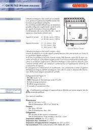
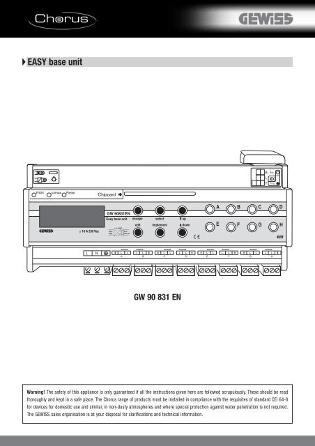
<strong>EASY</strong> <strong>base</strong> <strong>unit</strong><br />
μ 10 A 230 Vac<br />
GW 90831EN<br />
Easy <strong>base</strong> <strong>unit</strong><br />
- 5 ... 45°C<br />
230V~<br />
29V=<br />
50Hz<br />
320 mA<br />
escape select up<br />
edit implement<br />
down<br />
A<br />
E<br />
B<br />
F<br />
C<br />
G<br />
D<br />
H<br />
GW 90 831 EN<br />
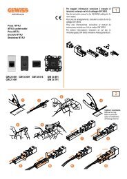
Warning! The safety of this appliance is only guaranteed if all the instructions given here are followed scrupulously. These should be read<br />
thoroughly and kept in a safe place. The Chorus range of products must be installed in compliance with the requisites of standard CEI 64-8<br />
for devices for domestic use and similar, in non-dusty atmospheres and where special protection against water penetration is not required.<br />
The GEWISS sales organisation is at your disposal for clarifications and technical information.
Rapid search<br />
Using the operating instructions<br />
Do you already have experience with EIB systems or are you already familiar with EIB <strong>EASY</strong> and want to quickly look over the most important information about the EIB<br />
<strong>EASY</strong> <strong>base</strong> <strong>unit</strong>? Then you should read the EIB <strong>EASY</strong> highlights. Is EIB <strong>EASY</strong> new to you? Then you should read EIB <strong>EASY</strong> from A to Z.<br />
EIB <strong>EASY</strong> highlights<br />
EIB <strong>EASY</strong> from A to Z<br />
Page 7<br />
Page 23<br />
Page 27<br />
Page 68<br />
Quick configuration<br />
(chapter 2, see "Configuration in three steps").<br />
The three most important steps for starting up the EIB <strong>EASY</strong> system<br />
are listed on one page.<br />
Configuration in detail<br />
(chapter 7, see "Configuration") Everything you need for<br />
configuration, illustrated by an example.<br />
Making settings, modifying, deleting and saving - everything you<br />
need to know about operating EIB <strong>EASY</strong><br />
(chapter 8, see " Operation ") All operations are explained in detail<br />
according to the menu structure.<br />
Error messages: causes and solutions<br />
Page 8<br />
Page 12<br />
Page 14<br />
Page 21<br />
Preparation - from installation to connection<br />
(chapter 3, see " Preparatory work") A description of the installation<br />
of the EIB <strong>EASY</strong> system.<br />
An overview of the system<br />
(chapter 4, see "The EIB <strong>EASY</strong> system") A description of EIB <strong>EASY</strong>,<br />
from functionality through to devices and planning of the system.<br />
Base <strong>unit</strong><br />
(chapter 5, see " Device description ") A description of the EIB <strong>EASY</strong><br />
<strong>base</strong> <strong>unit</strong> and its components. Includes overview, control elements and<br />
functions.<br />
Mounting<br />
(chapter 6, see " Mounting ") Description of the electrical connections<br />
of the EIB <strong>EASY</strong> <strong>base</strong> <strong>unit</strong>. Includes an example as well as suggestions<br />
for installation and mounting.<br />
Page 23<br />
Configuration in detail<br />
(chapter 7, see "Configuration") Everything you need for configuration,<br />
illustrated by an example.<br />
Page 27<br />
Valuable reference information<br />
Operation (chapter 8)<br />
Error messages, causes and solutions (chapter 9)<br />
Parameters (chapter 10)<br />
Technical data (chapter 11)<br />
Appendix (chapter 12)<br />
Page 85<br />
Application examples (chapter 12.4)<br />
3
Index<br />
1. General information<br />
1.1 EIB <strong>EASY</strong> ............................................................................................................................................................................6<br />
1.2 Symbols ..............................................................................................................................................................................6<br />
1.3 Guidelines ........................................................................................................................................................................6<br />
1.4 Proper use ........................................................................................................................................................................6<br />
2. Getting there quickly<br />
2.1 Configuration in three steps ....................................................................................................................7<br />
3. Preparatory work<br />
3.1 Installation ......................................................................................................................................................................8<br />
3.2 Laying the bus line ............................................................................................................................................10<br />
3.3 Crossings ......................................................................................................................................................................11<br />
3.4 Connecting bus devices to the bus..............................................................................................11<br />
4. The EIB <strong>EASY</strong> system<br />
4.1 Functionality ..............................................................................................................................................................12<br />
4.2 The advantages of the EIB <strong>EASY</strong> system..............................................................................12<br />
4.3 Possible terminal <strong>unit</strong> combinations ........................................................................................13<br />
5. Device description<br />
5.1 EIB <strong>EASY</strong> <strong>base</strong> <strong>unit</strong> components ....................................................................................................14<br />
5.1.1 General description ..............................................................................................................................................14<br />
5.1.2 Control elements......................................................................................................................................................15<br />
Status LEDs ..................................................................................................................................................................15<br />
Display ................................................................................................................................................................................15<br />
Control keys ..................................................................................................................................................................15<br />
Channel keys................................................................................................................................................................15<br />
5.1.3 Connections ..................................................................................................................................................................16<br />
Bus connection ..........................................................................................................................................................16<br />
Connection of electrical loads ..................................................................................................................16<br />
Mains connection....................................................................................................................................................16<br />
5.2 Functions........................................................................................................................................................................17<br />
5.2.1 System device<br />
(controller, functional <strong>unit</strong> of the EIB <strong>EASY</strong> <strong>base</strong> <strong>unit</strong>)....................................................17<br />
5.2.2 Power supply <strong>unit</strong> ..................................................................................................................................................17<br />
5.2.3 Chip card reader ......................................................................................................................................................17<br />
5.2.4 8-gang switching actuator ..........................................................................................................................17<br />
5.2.5 4-channel timer function ..............................................................................................................................19<br />
5.2.6 8 x 4 scene function............................................................................................................................................20<br />
4
Index<br />
6. Mounting<br />
6.1 Electrical connection of EIB <strong>EASY</strong> <strong>base</strong> <strong>unit</strong> ..................................................................21<br />
Connection example ............................................................................................................................................21<br />
Suggested installation ......................................................................................................................................22<br />
Suggested mounting ..........................................................................................................................................22<br />
7. Configuration<br />
7.1 EIB <strong>EASY</strong> <strong>base</strong> <strong>unit</strong>............................................................................................................................................23<br />
7.2 EIB <strong>EASY</strong> terminal <strong>unit</strong>s..............................................................................................................................23<br />
7.2.1 Requirements ..............................................................................................................................................................23<br />
7.2.2 General description ..............................................................................................................................................23<br />
7.2.3 Example ............................................................................................................................................................................24<br />
8. Operation<br />
8.1 Menu structure ......................................................................................................................................................27<br />
8.2 Control elements ..................................................................................................................................................28<br />
Display ................................................................................................................................................................................28<br />
Control keys ..................................................................................................................................................................30<br />
8.3 Menu ....................................................................................................................................................................................31<br />
Menu overview ..........................................................................................................................................................32<br />
8.4 Operation........................................................................................................................................................................33<br />
8.4.1 Settings ..............................................................................................................................................................................33<br />
Set date..............................................................................................................................................................................33<br />
Set time..............................................................................................................................................................................34<br />
Summer/Winter ........................................................................................................................................................35<br />
24/12 hours display ............................................................................................................................................35<br />
Button beep ..................................................................................................................................................................36<br />
8.4.2 Application ......................................................................................................................................................................37<br />
New function ................................................................................................................................................................37<br />
Parameters ....................................................................................................................................................................40<br />
Edit function ..................................................................................................................................................................42<br />
Program function ....................................................................................................................................................44<br />
Delete function ..........................................................................................................................................................45<br />
Search device..............................................................................................................................................................46<br />
Delete device ..............................................................................................................................................................47<br />
Replace device ..........................................................................................................................................................48<br />
Rename ..............................................................................................................................................................................50<br />
8.4.3 Project admin ..............................................................................................................................................................52<br />
Assign project name............................................................................................................................................52<br />
Save project ..................................................................................................................................................................54<br />
Load project ..................................................................................................................................................................56<br />
Delete project ..............................................................................................................................................................58<br />
Delete system ............................................................................................................................................................59<br />
Load word list ............................................................................................................................................................60<br />
Edit word list ................................................................................................................................................................61<br />
Delete card ....................................................................................................................................................................64<br />
8.4.4 Diagnosis..........................................................................................................................................................................65<br />
Test sensor ....................................................................................................................................................................65<br />
Identify device ............................................................................................................................................................66<br />
Service information ..............................................................................................................................................67<br />
9. Error messages, causes and solutions<br />
9.1 Behaviour in the event of a malfunction ..............................................................................68<br />
9.2 Troubleshooting table ....................................................................................................................................68<br />
10. Adjustable parameters<br />
10.1 8-gang switching actuator ....................................................................................................................80<br />
Switch-on time ..........................................................................................................................................................80<br />
Prewarning time ......................................................................................................................................................80<br />
10.2 4-channel timer mode ..................................................................................................................................80<br />
Switching time (1 - 4)........................................................................................................................................80<br />
Value (1 - 4) ..................................................................................................................................................................80<br />
11. Technical data<br />
11.1 General information ........................................................................................................................................81<br />
11.2 Controller (functional <strong>unit</strong> of the EIB <strong>EASY</strong> <strong>base</strong> <strong>unit</strong>) ..........................................81<br />
11.3 Power supply <strong>unit</strong> for bus line ..........................................................................................................81<br />
11.4 8-gang switching actuator ....................................................................................................................82<br />
11.5 4-channel timer mode ..................................................................................................................................82<br />
11.6 8 x 4 channel scene function ............................................................................................................82<br />
12. Appendix<br />
12.1 Forms ..................................................................................................................................................................................83<br />
12.2 Codes ..................................................................................................................................................................................84<br />
12.3 Standard word list ............................................................................................................................................84<br />
12.4 Application examples..................................................................................................................................85<br />
12.4.1 ON/OFF cyclical command on a generic actuator............................................................85<br />
12.4.2 ON/OFF command of a generic actuator with edge management ..............86<br />
12.4.3 Controlling and regulating a dimmer light ..............................................................................87<br />
12.4.4 Blinds control and regulation ..................................................................................................................88<br />
12.4.5 Scene function ........................................................................................................................................................89<br />
12.4.6 Scene function with dimmers or Base Unit actuators ................................................90<br />
12.4.7 Lighting with movement detector ......................................................................................................91<br />
12.4.8 Lighting with movement detector and local command<br />
and priority control..............................................................................................................................................92<br />
12.4.9 Room light monitoring with movement detector,<br />
light is switched on manually ................................................................................................................93<br />
12.4.10 Charges activation with time programming ........................................................................94<br />
12.4.11 Controlling awnings using wind sensor control ..............................................................95<br />
12.4.12 Zone thermal regulation (Master-Slave) ..................................................................................96<br />
12.5 Glossary ........................................................................................................................................................................97<br />
5
1. General information<br />
1.1 EIB <strong>EASY</strong><br />
Thank you for choosing the EIB <strong>EASY</strong> system from GEWISS.<br />
EIB <strong>EASY</strong> is a system of intelligent devices <strong>base</strong>d on KNX EIB.<br />
EIB <strong>EASY</strong> consists of the EIB <strong>EASY</strong> <strong>base</strong> <strong>unit</strong> and devices such as sensors, control<br />
elements, actuators, which will be referred to more generally as “terminal <strong>unit</strong>s”.<br />
The EIB <strong>EASY</strong> <strong>base</strong> <strong>unit</strong> automatically recognises the terminal <strong>unit</strong>s.<br />
They configure the system.<br />
The EIB <strong>EASY</strong> <strong>base</strong> <strong>unit</strong> supplies the bus with power. In addition, it also functions<br />
as an 8-gang switching actuator with 4-channel timer function and 8 x 4 scene<br />
functions.<br />
The devices comprising the system operate without a separate control <strong>unit</strong>.<br />
Information is exchanged directly from one device to another.<br />
This is what makes the EIB <strong>EASY</strong> system so flexible.<br />
The operating instructions provided here contain the following information:<br />
• Installation information (see "Installation", page 8)<br />
• Description of all <strong>base</strong> <strong>unit</strong> components (see "Device description" on page 14)<br />
• Overview of configuration (see "Getting there quickly" on page 7) and (see<br />
"Configuration", page 23)<br />
• Detailed operating instructions (see "Operation" on page 27)<br />
You can look up terms that you are not familiar with in the glossary<br />
(see "Glossary", page 97)<br />
Read the chapters "Getting there quickly" and "Configuration" if you want<br />
to start the system as soon as possible.<br />
For more detailed information, please refer to the chapter "Operation".<br />
1.2 Symbols<br />
In the following section, different symbols are used to indicate: "note", "caution"<br />
and "danger". The meaning of each type is seen below:<br />
Caution!<br />
This is a safety note in the form of a warning triangle labelled "Caution"<br />
used to indicate that devices, material and the environment are<br />
primarily at risk.<br />
Danger!<br />
This is a safety note in the form of a warning triangle labelled "Danger"<br />
used to indicate that persons are primarily at risk (risk of death or<br />
injury).<br />
1.3 Guidelines<br />
Note!<br />
The EIB <strong>EASY</strong> <strong>base</strong> <strong>unit</strong> must be protected from moisture, dirt and<br />
damage during transportation, storage and operation.<br />
Danger!<br />
Danger! Electric current!<br />
Note!<br />
Work on the installation bus may only be carried out by qualified<br />
electricians.<br />
Note!<br />
Only materials supplied or approved by GEWISS or materials that<br />
comply with applicable norms, guidelines, rules and regulations may<br />
be used.<br />
Note!<br />
The <strong>EASY</strong> <strong>base</strong> <strong>unit</strong> will be damaged if used improperly!<br />
Note!<br />
The <strong>EASY</strong> <strong>base</strong> <strong>unit</strong> may only be used under the operating conditions<br />
specified in the technical data (see "Technical data" on page 81).<br />
Note!<br />
Repair work on the <strong>EASY</strong> <strong>base</strong> <strong>unit</strong> may only be carried out by GEWISS.<br />
1.4 Proper use<br />
The EIB <strong>EASY</strong> <strong>base</strong> <strong>unit</strong> is an EIB product. As with all GEWISS Home and Building<br />
Automation devices, it was developed in accordance with the guidelines of the<br />
KNX association.<br />
The EIB <strong>EASY</strong> system can be used in blocks of flats, detached family houses and<br />
in the commercial sector.<br />
The EIB <strong>EASY</strong> <strong>base</strong> <strong>unit</strong> is used for starting up and configuring the <strong>EASY</strong> system.<br />
The EIB <strong>EASY</strong> <strong>base</strong> <strong>unit</strong> consists of:<br />
• A 320mA power supply <strong>unit</strong><br />
• 8-gang switching actuator<br />
• 4-channel timer<br />
• Scene module 8x4 channels<br />
The <strong>base</strong> <strong>unit</strong> can manage a bus system for up to 63 additional EIB Easy devices.<br />
Note!<br />
This symbol is not a safety note, but instead is intended to facilitate<br />
understanding of various processes.<br />
6
2. Getting there quickly<br />
2.1 Configuration in three steps<br />
μ 10 A 230 Vac<br />
GW 90831EN<br />
Easy <strong>base</strong> <strong>unit</strong><br />
230V~<br />
50Hz<br />
- 5 ... 45°C<br />
29V=<br />
320 mA<br />
escape select up<br />
edit implement<br />
down<br />
1 - Set up project<br />
Start screen<br />
Select “Main menu”: Press “Implement” once.<br />
μ 10 A 230 Vac<br />
GW 90831EN<br />
Easy <strong>base</strong> <strong>unit</strong><br />
230V~<br />
50Hz<br />
- 5 ... 45°C<br />
29V=<br />
320 mA<br />
escape select up<br />
edit implement<br />
down<br />
Main menu<br />
Select “Application”: Press “Down” once Press “Implement” once.<br />
μ 10 A 230 Vac<br />
GW 90831EN<br />
Easy <strong>base</strong> <strong>unit</strong><br />
230V~<br />
50Hz<br />
- 5 ... 45°C<br />
29V=<br />
320 mA<br />
escape select up<br />
edit implement<br />
down<br />
Application Menu<br />
Select “New function”: Press “Implement”once.<br />
2 - Select devices<br />
A<br />
B<br />
C<br />
D<br />
Select the sensors and actuators relating to the function by pressing the<br />
command buttons and the actuator buttons, then press “Implement” to confirm.<br />
select<br />
implement<br />
up<br />
down<br />
E<br />
F<br />
G<br />
H<br />
μ 10 A 230 Vac<br />
GW 90831EN<br />
Easy <strong>base</strong> <strong>unit</strong><br />
230V~<br />
50Hz<br />
- 5 ... 45°C<br />
29V=<br />
320 mA<br />
escape select up<br />
edit implement<br />
down<br />
3 - Set up function<br />
Press “Implement” to create a function.<br />
GW 90831EN<br />
Easy <strong>base</strong> <strong>unit</strong><br />
escape select up<br />
Press “Implement” to select the sensor function.<br />
μ 10 A 230 Vac<br />
- 5 ... 45°C<br />
230V~<br />
29V=<br />
50Hz<br />
320 mA<br />
edit<br />
implement<br />
down<br />
μ 10 A 230 Vac<br />
GW 90831EN<br />
Easy <strong>base</strong> <strong>unit</strong><br />
230V~<br />
50Hz<br />
- 5 ... 45°C<br />
29V=<br />
320 mA<br />
escape select up<br />
edit implement<br />
down<br />
Press “Implement” to confirm the proposed function name.<br />
7
3. Preparatory work<br />
3.1 Installation<br />
4<br />
5<br />
EIB <strong>EASY</strong> devices are connected to one another using a bus line.<br />
The bus devices exchange information via the bus line (controls, statuses, etc).<br />
In this way, sensors and actuators can be combined into <strong>unit</strong>s with a specific<br />
function.<br />
Base <strong>unit</strong> (the <strong>base</strong> <strong>unit</strong> supplies the bus with power).<br />
1<br />
2 3<br />
Bus device (e.g. a 4 channel Easy push-button – flush mounted GW 14 751).<br />
Bus device (e.g. 1 channel 16A Easy actuator - flush mounted GW 14 766).<br />
Bus line (the bus line used for communication between the bus devices and to supply<br />
the bus devices with power).<br />
Connection (all bus devices are connected in parallel to the bus line. The bus line is<br />
connected to the bus supply terminal).<br />
The EIB <strong>EASY</strong> system makes it possible to form a line.<br />
A line is an organisational <strong>unit</strong>. A line requires a <strong>base</strong> <strong>unit</strong>, and up to 63 additional<br />
bus devices can be connected.<br />
1 2<br />
63<br />
In the event that consumption is over 320mA (and the LED I>max comes<br />
on) it is recommended to increase the power supply to the line using<br />
160mA (GW 90 703) or 320mA (GW 90 702) power supply <strong>unit</strong>s. To limit<br />
compensation currents, 200 m of bus line should be laid between both<br />
power supply <strong>unit</strong>s.<br />
350 m<br />
350 m<br />
700 m<br />
Cable lengths:<br />
• The bus line between the power supply (<strong>base</strong> <strong>unit</strong>) and the farthest removed<br />
bus device must not exceed 350 m in length.<br />
• The maximum line length between two bus devices is 700 m.<br />
• The bus line can be up to 1000 m long.<br />
8
3. Preparatory work<br />
Linear structure<br />
Here it is possible, of course, to follow the installation of the power line by<br />
selecting arrangements with star, tree or linear structures or any combinations of<br />
these within a line.<br />
Star structure<br />
Tree structure<br />
Note!<br />
When installing the bus line, no loops should be formed.<br />
Loops result in unwanted signals and surges.<br />
2 1 1 2<br />
4<br />
Loop formation when installing the bus line<br />
230 V ac line or bus wire<br />
WRONG<br />
3 3<br />
RIGHT<br />
Bus wire<br />
Bus device<br />
The diagram on the left shows the loop<br />
9
3. Preparatory work<br />
3.2 Laying the bus line<br />
Type GEWISS Code Cabling<br />
YCYM 2 x 2 x 0.8<br />
YCYM 1 x 2 x 0.8<br />
GW 90 582<br />
GW 90 583<br />
The bus line is suitable for permanent installation in dry, damp or wet rooms, on, in or under plaster and in pipes.<br />
The bus line can be installed outdoors provided it is protected from direct sunlight<br />
3<br />
2 1<br />
Insulated wires<br />
Screen foil<br />
Casing/insulation<br />
Stability wire<br />
4<br />
The bus lines have 2 or 4 wires:<br />
- red: +EIB<br />
- black: -EIB<br />
- yellow: optional, SELV + auxiliary power supply<br />
- white: optional, SELV - auxiliary power supply<br />
Wires are twisted and have a diameter of 0.8 mm. On the outside, they are<br />
protected against electrical fields by a screen foil.<br />
They contain an additional wire for mechanical stability.<br />
These bus lines enable error-free communication in accordance with EIB<br />
standards (EN 50090-9-1 and EN 50090-2-2) and ensure safety separation from<br />
the power network.<br />
In addition, the connected terminal <strong>unit</strong>s are supplied with power via the bus line.<br />
Only actuators that operate loads such as lights or electrical motors have to be<br />
connected to the 230 V power network.<br />
It is safe for the user to touch the bus line. The bus is separated from the power<br />
network. It operates on low voltage up to 30 V ±1 V. All requirements defined<br />
within EN 50 090-2-2 standard have been met.<br />
Note!<br />
The electrical installation is carried out by a qualified electrician in<br />
accordance with the installation regulations for power systems, in<br />
particular with EN 50 090 standard.<br />
The same installation regulations that apply to power systems also<br />
apply to bus lines and bus devices.<br />
No additional electrical installation tools, assembly aids or measuring<br />
and testing devices are required for installation of the bus lines.<br />
10
3. Preparatory work<br />
3.3 Connecting bus devices to the bus<br />
Connection terminal and bus power supply<br />
Connect the bus cable’s red wire to the terminal’s red connector (+) and the black<br />
wire to the black connector (-). Up to 4 bus lines (wires of the same colour in the<br />
same connector) can be connected to the bus terminal.<br />
Insulate the screen, the electrical continuity conductor and the remaining white<br />
and yellow wires of the bus cable (should a bus cable with 4 conductors be used),<br />
which are not needed.<br />
Insert the bus connector into the special feet of the device.<br />
The fastener guides determine the direction it should be inserted.<br />
Insulate the bus terminal using the relative cover, which must be screwed onto<br />
the device. The cover guarantees that the power cables and the bus cables are<br />
separated by at least 4 mm.<br />
Note!<br />
The stability wire of the screen must not be damaged.<br />
Danger!<br />
Danger! Electric current!<br />
Unused wires and the stability wire must not touch live parts or the<br />
earth potential.<br />
3.4 Insulation distances<br />
230 V<br />
bus line<br />
230V power and bus lines as well as accompanying installation devices can be<br />
installed next to each other in distribution boards.<br />
The following should be observed when doing this:<br />
• Insulated wires of encased 230V power lines and the installation bus line can<br />
be laid without a gap between them.<br />
• Insulated wires of 230 V lines must have a gap of at least 4 mm from the<br />
insulated wires of bus lines or there must be the same level of insulation<br />
through a separating web or insulating sleeving on the wires of the bus line.<br />
Bus<br />
4 mm<br />
230 V<br />
Bus wires and 230 V wires can be present in the same installation box if the<br />
installation box makes it possible to ensure that the bus wires and 230 V wires<br />
are separated safely.<br />
If bus and power devices are used together in flush-mount combinations, parts<br />
carrying a current must remain protected against direct contact after the shared<br />
cover has been removed.<br />
The bus line and devices should be treated like power systems with regard to<br />
public telecommunication systems.<br />
The same applies to electrical circuits of telecommunication systems that are not<br />
SELV or PELV circuits.<br />
All SELV or PELV circuits can be laid without a gap next to the bus line.<br />
All that is required is basic insulation suitable for the voltage level.<br />
Note!<br />
SELV (Safety Extra Low Voltage) is used for a secondary-side nonearthed<br />
low voltage circuit.<br />
PELV (Protected Extra Low Voltage) indicates a secondary-side earthed<br />
low voltage circuit. EIB <strong>EASY</strong> has a SELV circuit.<br />
11
Merten<br />
instabus<br />
Easy Schaltaktor<br />
REG-K/8 x 230/10<br />
A<br />
B C D<br />
E F G H<br />
B + -<br />
Bus ON<br />
L<br />
XY<br />
T Prog.<br />
7771 08<br />
10A 230V AC<br />
4. The EIB <strong>EASY</strong> system<br />
4.1 Functionality<br />
1<br />
premere push<br />
2<br />
action azione<br />
information<br />
informazione<br />
The EIB <strong>EASY</strong> system consists of devices with special functions such as<br />
switching, dimming etc.<br />
The devices are all connected to each other by a bus line.<br />
The devices can communicate with each other via the bus line.<br />
For example, a sensor (light switch, button) initiates a switching process in which<br />
an actuator (breaker or switching contacts) carries out the switching process.<br />
The actuator confirms the process to the sensor.<br />
In order for the devices to be able to function in this way, the system has to be<br />
configured correctly with the EIB <strong>EASY</strong> <strong>base</strong> <strong>unit</strong>.<br />
Conventional switches consist of a rocker that is mechanically linked with the<br />
switching contacts of the switch insert.<br />
The load must be connected to the switch insert directly on site.<br />
With an EIB <strong>EASY</strong> bus installation, a functional and/or spatial separation in the sensor<br />
(button) and actuator (switching contact) is carried out.<br />
The information is transmitted via the bus.<br />
premere push<br />
RUN<br />
A B C D<br />
E F G H<br />
azione action<br />
EIB <strong>EASY</strong> system allows you to create a new function in which actuators and<br />
sensors are functionally linked with each other.<br />
The EIB <strong>EASY</strong> <strong>base</strong> <strong>unit</strong> supports you by automatically recognising the actuators<br />
and sensors and presenting you with a list including the existing functions for you<br />
to choose from. You can create a new function simply by selecting it.<br />
The function must have a name assigned to it.<br />
The EIB <strong>EASY</strong> <strong>base</strong> <strong>unit</strong> subsequently transmits the connection information to the<br />
relevant actuators and sensors.<br />
All the functions that you set up in this way together form the project.<br />
After you have finished, you must save the project on the chip card.<br />
The EIB <strong>EASY</strong> <strong>base</strong> <strong>unit</strong> remains part of the installation.<br />
4.2 The advantages of the EIB <strong>EASY</strong> system<br />
The EIB <strong>EASY</strong> system is <strong>base</strong>d on the KNX/EIB.<br />
EIB <strong>EASY</strong> is just as flexible but easier to set up.<br />
The installation is almost identical to the conventional installation.<br />
The bus line is simply laid next to the 230 V line.<br />
All you need to set it up is an EIB <strong>EASY</strong> <strong>base</strong> <strong>unit</strong>. As the terminal <strong>unit</strong>s are<br />
recognised automatically, they only have to be combined in functions.<br />
The EIB <strong>EASY</strong> system is simple and easy to understand.<br />
Once in operation, the EIB <strong>EASY</strong> <strong>base</strong> <strong>unit</strong> supplies the bus with power.<br />
In addition, the EIB <strong>EASY</strong> <strong>base</strong> <strong>unit</strong> functions as an 8-gang switching actuator.<br />
Eight switching channels can be used immediately via manual control.<br />
The assignment of functions is made particularly simple and easy to understand<br />
by the keys on the <strong>base</strong> <strong>unit</strong>.<br />
In addition, an integrated four-channel timer is also provided.<br />
No additional devices are required. Time management operations are carried out<br />
on the LC display and with the <strong>base</strong> <strong>unit</strong> buttons.<br />
In addition, a scene function for four actuator groups is included.<br />
The following information can be found on the instructions sheets for each<br />
individual product:<br />
• Function<br />
• Suggestions for mounting and installation<br />
• Configuration<br />
• Configuration Parameter<br />
• Technical data<br />
12
4. The EIB <strong>EASY</strong> system<br />
4.3 Planning possible combinations<br />
Planning and planning documents (for template see "Forms", page 83) can be an<br />
important aid when setting up an EIB <strong>EASY</strong> system.<br />
The module is organised by function.<br />
- Make a note of which devices are being installed in which room.<br />
- Identify the function<br />
- Mark down the devices that implement the function<br />
- Mark down the channels involved, the function type, the parameters and their<br />
relative values<br />
The planning documents will help you to keep track of things during the<br />
configuration phase and assist you in making changes later on.<br />
CUSTOMER<br />
Name: Bianchi Gianpietro<br />
Project: Semi-detached villa<br />
Address: via A.Volta 1 - Cenate sotto<br />
Function<br />
Staircase lights Floor First Function No 5<br />
Function name*<br />
Act. Switch Room/board Staircase<br />
Device<br />
N° Code Description<br />
GW90834<br />
GW90834<br />
GW14756<br />
GW14666<br />
4 channel Easy contact interface<br />
4 channel Easy contact interface<br />
IR movement detector with Easy<br />
twilight switch<br />
1 channel 16 A Easy actuator<br />
Channel Channel ID** Sensor Function Parameter Parameter value<br />
1<br />
2<br />
2.1<br />
2.2<br />
3<br />
4<br />
Timer act.<br />
Priority activation<br />
Timer act.<br />
priority control<br />
Transmiss. period<br />
activation time<br />
prewarning time<br />
on/down<br />
45 seconds<br />
1.5 minutes<br />
15 seconds<br />
* Function name = name assigned to the <strong>base</strong> <strong>unit</strong> function<br />
** Channel ID = identification of the channel inside the <strong>base</strong> <strong>unit</strong> using a device<br />
ID channel number format<br />
Note!<br />
Calculate how many metres of 230 V line, bus line, bus supply<br />
terminals and installation boxes you will need.<br />
Note the maximum line lengths (see page 8).<br />
13
5. Device description<br />
5.1 EIB <strong>EASY</strong> <strong>base</strong> <strong>unit</strong> components<br />
5.1.1 Overview<br />
The EIB <strong>EASY</strong> <strong>base</strong> <strong>unit</strong> is used to configure an EIB <strong>EASY</strong> system.<br />
It also contains a power supply <strong>unit</strong> for the 320mA bus line, a real-time clock, a<br />
weekly timer with four switching channels, a scene component with 8 x 4 scene<br />
functions and an 8-gang switching actuator with keys and status display for local<br />
operation. Loads are switched via floating relays, one per channel (A - H).<br />
1 2 3<br />
4 5 6<br />
μ 10 A 230 Vac<br />
GW 90831EN<br />
Easy <strong>base</strong> <strong>unit</strong><br />
- 5 ... 45°C<br />
230V~<br />
29V=<br />
50Hz<br />
320 mA<br />
escape select up<br />
edit implement down<br />
A<br />
E<br />
B<br />
F<br />
C<br />
G<br />
D<br />
H<br />
8<br />
7<br />
Front:<br />
LEDs inform you about the status of the power supply<br />
Display<br />
Chip card reader for backing up the project data<br />
Control keys of the EIB <strong>EASY</strong> <strong>base</strong> <strong>unit</strong> for navigation through the menus and for<br />
configuration<br />
Channel keys (A - H) for local operation of the 8-channel switching actuator<br />
Labelling field<br />
Connection of electrical loads, 2-pin<br />
9<br />
10 11<br />
12<br />
Mains connection, ac 230 V (L, N, PE)<br />
Behind the cover:<br />
Reset switch<br />
Bus connection<br />
Programming key<br />
Red LED programming indicator<br />
14
5. Device description<br />
Status LEDs<br />
5.1.2 Control elements<br />
Three LEDs indicate the status of the EIB <strong>EASY</strong> <strong>base</strong> <strong>unit</strong> (BUS).<br />
• green LED, RUN<br />
• red LED, I > Imax<br />
• red LED, Reset<br />
In normal operation, only the green LED is on.<br />
The current to the terminal <strong>unit</strong>s has not exceeded the maximum permissible<br />
current (320mA).<br />
If the current slightly exceeds the maximum permissible current, the green LED<br />
and the red (I > Imax) LED light up. The bus voltage remains stable.<br />
As soon as the current significantly exceeds the maximum permissible current<br />
(short circuit), the green LED will light up and the red LED (I > Imax) will begin to<br />
flash or only the red LED will be illuminated.<br />
If the terminal <strong>unit</strong>s are reset with the slider switch, the second red LED will light<br />
up (Reset).<br />
Display<br />
The display text guides the user through the various steps of operation.<br />
Control keys<br />
1<br />
2 3<br />
The control keys are used to navigate through the display menus.<br />
The following options are provided:<br />
escape<br />
GW 90831<br />
Easy <strong>base</strong> <strong>unit</strong><br />
- 5 ... 45°C<br />
escape select up<br />
edit implement down<br />
select<br />
up<br />
down<br />
230V~<br />
50Hz<br />
29V=<br />
320 mA<br />
implement<br />
edit<br />
6 5 4<br />
Channel keys<br />
A<br />
B<br />
C<br />
D<br />
Each channel of the 8-gang switching actuator has a channel key.<br />
The channel keys are marked from A to H.<br />
The channel key allows a channel to be controlled manually (switched on/off).<br />
In addition, the channel key can be used to identify a channel during the<br />
configuration phase.<br />
The channel keys are white. Each key is backlit by a red LED.<br />
The LED lights up to indicate the closure status of the corresponding output<br />
contact.<br />
E<br />
F<br />
G<br />
H<br />
15
5. Device description<br />
Bus connection<br />
5.1.3 Connections<br />
Bus<br />
A bus supply terminal is fitted to the bus line.<br />
The bus supply terminal is attached to the pins of the bus connection.<br />
The cover ensures the safety separation of the bus connection and 230 V line.<br />
Connection of electrical loads<br />
E<br />
F<br />
G<br />
H<br />
The electrical loads are connected to the EIB <strong>EASY</strong> <strong>base</strong> <strong>unit</strong> (8-gang switching<br />
actuator) with a 3-pin connector.<br />
The connections lead to the relay contacts.<br />
The contacts are open and potential-free when idle.<br />
Currents of up to 10 A can be switched.<br />
The phase (L) can be looped using a pluggable bridge (see "Electrical connection<br />
of EIB <strong>EASY</strong> <strong>base</strong> <strong>unit</strong>", page 21).<br />
Mains connection<br />
μ 10 A 230 Vac<br />
230V~<br />
50Hz<br />
5 ... 45 C<br />
29<br />
32<br />
There is a single-phase mains connection with a 3-pin connector.<br />
16
5. Device description<br />
5.2 Functions<br />
5.2.1 Configuration <strong>unit</strong><br />
In its function as configuration <strong>unit</strong>, the EIB <strong>EASY</strong> <strong>base</strong> <strong>unit</strong> is a configuration tool<br />
for an easy, user-guided configuration of an EIB <strong>EASY</strong> system (line).<br />
All the necessary steps for configuration are indicated in the display.<br />
The user only has to select the functions of the terminal <strong>unit</strong>s and set the device<br />
parameters (see "Operation", page 33).<br />
5.2.2 Power supply <strong>unit</strong><br />
The power supply <strong>unit</strong> delivers the power for the terminal <strong>unit</strong>s via the bus.<br />
It provides a stable output voltage of 30 V +/-1 V (SELV) with a maximum current<br />
of 320 mA.<br />
The power supply <strong>unit</strong> is short-circuit-proof.<br />
In the event of an overload, the self-holding fuse is activated.<br />
When the fuse is tripped, the green LED will turn off (RUN).<br />
- Eliminate the cause of the overload.<br />
To reset the fuse, it is necessary to press the reset switch (switch off for approx.<br />
2 s with slider switch).<br />
5.2.3 Chip card reader<br />
The chip card reader allows you to save project data on a chip card.<br />
By doing this, you can create a backup copy of your information that can be<br />
transferred from the chip card to the <strong>EASY</strong> <strong>base</strong> <strong>unit</strong> if needed.<br />
The chip card that is used is formatted as a project backup card.<br />
For more information on how to do this, see "Save project", page 54.<br />
5.2.4 8-gang switching actuator<br />
The 8-gang switching actuator in the EIB <strong>EASY</strong> <strong>base</strong> <strong>unit</strong> has eight independent,<br />
potential-free, switchable relay outputs (A - H).<br />
They enable the switching of lights and other loads.<br />
Loads can be switched using both an externally assigned push-button and using<br />
the built-in keys (A - H).<br />
The status of the relay output is indicated by a red LED in the channel key.<br />
The relay is closed when the LED is on.<br />
The load is connected to the corresponding channel.<br />
Switching<br />
Switch on load:<br />
Press the key of the corresponding channel (A - H). The red LED (status display)<br />
in the key lights up. The relay status is signalled via the bus.<br />
Switch off load:<br />
Press the key again. The red LED in the key turns off.<br />
The new relay status is signalled via the bus.<br />
17
5. Device description<br />
External, assigned button<br />
The actuator channel activates or deactivates the electric load when it receives<br />
ON/OFF commands sent, for example, by a contacts interface or a button pad<br />
configured in ON/OFF Cyclic Switching or Edge Management mode.<br />
Switch on load:<br />
Press the switch-on button. The status display of the channel lights up.<br />
If the button has a display, it also lights up (relay status feedback).<br />
Switch off load:<br />
Press switch-off button. The status display of the channel turns off.<br />
The display in the push-button, if present, turns off (relay status feedback).<br />
Timer mode<br />
The actuator activates the connected electric load for the time determined by the<br />
“Activation Time” parameter (from 1 second to 24 hours) and deactivates when<br />
it elapses. This is the setting for the staircase light, for example. If the dimmer<br />
actuator receives another timed ON command during the activation time, the<br />
time count restarts from the beginning. The relay is deactivated and the counter<br />
is reset when it receives an OFF command. The relay is deactivated and the<br />
counter is reset when it receives an OFF command or a scene is activated which<br />
includes the OFF command by the actuator.<br />
The “Prewarning time” parameter can enable the switch off warning signal: in<br />
this case the relay opens briefly (the light goes off for a second) when the time<br />
set on the parameter remains before the timer is due to switch off. If necessary<br />
it will be possible to send another timed command before the light switches off.<br />
The red LED comes on when the relay contact is closed.<br />
Priority controls<br />
The actuator switches the relay to the ON or OFF status transmitted by the device<br />
(contacts interface) which sends the priority control.<br />
Until it receives a command cancelling the forcing, the actuator ignores all other<br />
commands received including those from the front buttons.<br />
If no other commands are received, at the end of forcing the actuator returns to<br />
the condition before its actuation.<br />
On the contrary the status remains that of the last command received.<br />
The red LED comes on when the relay contact is closed.<br />
"Priority control" is a safety function. It locks all other functions in the switching<br />
actuator until it is deactivated. It can only be deactivated using the release key.<br />
18
5. Device description<br />
5.2.5 4-channel timer function (weekly timer)<br />
The EIB <strong>EASY</strong> <strong>base</strong> <strong>unit</strong> provides four independent channels for the timed<br />
triggering of events, e.g. closing blinds every day at 6:00 p.m.<br />
Each of the four channels offers four independent switching times that can be set<br />
by selecting parameters.<br />
The switching times can specify a particular time, e.g. Monday, 2:30 p.m., or a<br />
cyclically recurring time, e.g. every day at 7:00 p.m.<br />
The parameter for the switching time specifies the day of the week, hour and<br />
minute.<br />
It is possible to establish the type of switching, using a parameter, for each of the<br />
4 switching times for each channel.<br />
The following switching processes can be triggered:<br />
• Switching: It is possible to select:<br />
- Switching on<br />
- Switching off<br />
• Shutters or blinds up/down: it is possible to select<br />
- up<br />
- down<br />
• Dimming value: it is possible to select:<br />
- off<br />
- 100%<br />
- 90%<br />
- 80%<br />
- 70%<br />
- 60%<br />
- 50%<br />
- 40%<br />
- 35%<br />
- 30%<br />
- 25%<br />
- 20%<br />
- 15%<br />
- 10%<br />
- 5%<br />
- 2.5%<br />
The switching time is calculated by comparing the internal clock with the<br />
parameter for the switching time.<br />
The internal clock works independently of the 230 V mains supply.<br />
The secure time <strong>base</strong> is maintained even if there is a power failure.<br />
The bridging time is at least 2 hours.<br />
19
5. Device description<br />
5.2.6 8 x 4 scene function<br />
A scene is the combination of several terminal <strong>unit</strong>s together with their respective<br />
switching states, e.g. a dimmer that is set to 50% brightness and a standard<br />
lamp that is switched on.<br />
It is necessary to use the scene module when you intend to include the<br />
following in the scene:<br />
- Dimmer actuators (GW 90 841, GW 90 842)<br />
- Base <strong>unit</strong> actuator channels<br />
If you do not intend to include the above devices in the scene, it is not<br />
necessary to use the scene module as the terminal <strong>unit</strong>s are able to<br />
manage the scene on their own.<br />
The <strong>EASY</strong> <strong>base</strong> <strong>unit</strong> allows you to create eight scenes on any group of devices,<br />
on the condition that the total number of dimmer actuators (GW 90 841,<br />
GW 90 842) and <strong>base</strong> <strong>unit</strong> actuator channels are no more than 4.<br />
It is also possible, for instance, to create a scene which includes:<br />
- N. 2 1 channel 16A Easy actuator – flush-mount (GW 14 766)<br />
- N. 1 4 channel 16A Easy actuator – DIN rail (GW 90 836)<br />
- N. 2 1 channel 8A Easy motor command actuator – flush-mount (GW 14 767)<br />
- N. 2 400W Easy resistive-inductive dimmer actuator – DIN rail (GW 90 841)<br />
- N. 2 <strong>base</strong> <strong>unit</strong> channel actuators<br />
Scenes are programmed and permanently saved, i.e. they will still be available<br />
even after a power failure.<br />
Programming means that the switching states of the terminal <strong>unit</strong>s are recorded<br />
and saved under a scene number.<br />
Programming is triggered by an external sensor, e.g. <strong>EASY</strong> push-button insert,<br />
Easy 4 channel – flush-mount (GW 14 752).<br />
The saved switching states are transmitted via the bus to the terminal <strong>unit</strong>s.<br />
A scene is activated by a command device (button panel channel, a button<br />
connected to a contact interface)<br />
20
6. Mounting<br />
6.1 Electrical connection of EIB <strong>EASY</strong> <strong>base</strong> <strong>unit</strong><br />
Danger!<br />
The switch outputs have bistable relays.<br />
Strong vibrations during transport can cause the switching contact of<br />
the outputs to change to the switched on state.<br />
Be careful when connecting to the mains!<br />
The outputs may carry an electrical current!<br />
Connection example<br />
L<br />
L<br />
L<br />
L<br />
L<br />
L<br />
N<br />
10A<br />
10A<br />
10A<br />
10A<br />
10A<br />
10A<br />
Bus<br />
+-<br />
-<br />
+<br />
Channel Canale A<br />
Channel Canale B<br />
Channel Canale C<br />
Channel Canale D<br />
Channel Canale E<br />
Channel Canale F<br />
Channel Canale G<br />
Channel Canale H<br />
L<br />
L<br />
L<br />
L<br />
L<br />
L<br />
L<br />
L<br />
L<br />
L<br />
L<br />
L<br />
L<br />
L<br />
L<br />
L<br />
L<br />
L<br />
L<br />
L<br />
L<br />
L<br />
L<br />
L<br />
L<br />
N<br />
In the example, two variations are shown. Channels A, B and C, D are provided<br />
with one phase each. The phases are looped through a bridge on the device.<br />
Channels E, F, G and H are each connected separately to one phase.<br />
Note!<br />
We recommend using a separate fuse for the <strong>base</strong> <strong>unit</strong> in order to<br />
ensure that power is supplied to the bus system safely.<br />
21
- 5 ... 45°C<br />
230V~<br />
29V=<br />
50Hz<br />
320 mA<br />
6. Mounting<br />
Suggested installation<br />
Bus<br />
Connect the red bus wire to the red terminal (+) and the black one to the black<br />
terminal (-).<br />
2<br />
The screen and the stability wire of the bus lines are not required. Insulate and<br />
tie back.<br />
1<br />
μ 10 A 230 Vac<br />
230V~<br />
50Hz<br />
29V=<br />
320 mA<br />
Connect to the mains<br />
3<br />
29V=<br />
320 mA<br />
nit escape select up<br />
edit implement down<br />
E<br />
F<br />
G<br />
H<br />
Connect the 8-channel connections (A-H) to the 3-gang screw terminals as<br />
shown in the example. Plug the screw terminals into the EIB <strong>EASY</strong> <strong>base</strong> <strong>unit</strong>.<br />
It is possible to connect multiple channels to a single phase, using the bridges.<br />
4<br />
5<br />
Suggested mounting<br />
2<br />
A<br />
B<br />
C<br />
D<br />
GW 90831EN<br />
μ 10 A 230 Vac<br />
Easy <strong>base</strong> <strong>unit</strong> escape select up<br />
edit implement down<br />
E<br />
F<br />
G<br />
H<br />
1<br />
Connect the EIB <strong>EASY</strong> <strong>base</strong> <strong>unit</strong> as shown in the example and mount it onto a DIN<br />
rail EN 50022.<br />
1 - Insert the device’s lower coupling in the DIN rail.<br />
2 - Push the device upwards to compress the retainer springs.<br />
3 - Place the device on the DIN rail and lower it, checking that the top coupling<br />
connects onto the rail.<br />
22
7. Configuration<br />
7.1 EIB <strong>EASY</strong> <strong>base</strong> <strong>unit</strong><br />
Start screen<br />
Main menu<br />
Settings<br />
Date/Time<br />
Set date<br />
Set time<br />
Summer/Winter<br />
24/12 hours display<br />
System<br />
Button beep<br />
Protection<br />
Application<br />
New function<br />
Parameters<br />
Edit function<br />
Program function<br />
Delete function<br />
Search device<br />
Delete device<br />
Replace device<br />
Rename<br />
Rename device<br />
Rename channel<br />
Rename function<br />
Project admin<br />
Project name<br />
Save project<br />
Load project<br />
Delete project<br />
Delete system<br />
Load word list<br />
Edit word list<br />
Delete card<br />
Configuration with the help of the EIB <strong>EASY</strong> <strong>base</strong> <strong>unit</strong> is described in the following<br />
section.<br />
The bus is supplied with power from the power supply <strong>unit</strong>. The slider switch is<br />
set to "ON".<br />
- Select the New function menu<br />
The components are recognised automatically by the EIB <strong>EASY</strong> <strong>base</strong> <strong>unit</strong>.<br />
7.2 EIB <strong>EASY</strong> terminal <strong>unit</strong>s<br />
7.2.1 Requirements<br />
• You have completed the installation.<br />
• All the devices have been installed and connected to the bus line.<br />
• The bus is connected to a power supply.<br />
• The electrical loads are connected to the terminal <strong>unit</strong>s and the 230 V line has<br />
been laid and connected.<br />
7.2.2 Overview<br />
Note!<br />
For more details on operation, see "Operation", page 27.<br />
For an overview, see "Configuration in three steps" on page 7.<br />
Warning!<br />
Bus voltage must be present before the mains voltage is switched on<br />
so that the relay outputs of the actuators are disabled!<br />
- Select the New function menu.<br />
The EIB <strong>EASY</strong> <strong>base</strong> <strong>unit</strong> automatically recognises the terminal <strong>unit</strong>s and displays<br />
them in the list (see "The New function (211) menu will appear.", page 38).<br />
Connect the terminal <strong>unit</strong>s (sensor and actuator) to one another.<br />
If a terminal <strong>unit</strong> has multiple channels, e.g. a 4-gang button, press the button<br />
that is to be used in the function.<br />
The channel will then be selected in the list.<br />
For a terminal <strong>unit</strong> that has no control element such as a button, a sensor, e.g.<br />
the dimmer actuator (GW 90 841), it is necessary to hold down the programming<br />
key for a few seconds (> 2 s).<br />
The red LED on the terminal <strong>unit</strong> will light up during the recognition process.<br />
For a detailed description, please refer to the operating instructions for each<br />
terminal <strong>unit</strong>.<br />
Diagnosis<br />
Test sensor<br />
Ident. device<br />
Service infomation<br />
23
7. Configuration<br />
7.2.3 Example<br />
- Enter the terminal <strong>unit</strong>s in your planning documents.<br />
CUSTOMER<br />
Name: Bianchi Gianpietro<br />
Project: Semi-detached villa<br />
Address: via A.Volta 1 - Cenate sotto<br />
Function<br />
Staircase lights Floor First Function No 5<br />
Function name*<br />
Act. Switch Room/board Staircase<br />
Device<br />
N° Code Description<br />
GW90834<br />
GW90834<br />
GW14756<br />
GW14666<br />
4 channel Easy contact interface<br />
4 channel Easy contact interface<br />
IR movement detector with Easy<br />
twilight switch<br />
1 channel 16 A Easy actuator<br />
Channel Channel ID** Sensor Function Parameter Parameter value<br />
1<br />
2<br />
2.1<br />
2.2<br />
3<br />
4<br />
Timer act.<br />
Priority activation<br />
Timer act.<br />
priority control<br />
Transmiss. period<br />
activation time<br />
prewarning time<br />
on/down<br />
45 seconds<br />
1.5 minutes<br />
15 seconds<br />
* Function name = name assigned to the <strong>base</strong> <strong>unit</strong> function<br />
** Channel ID = identification of the channel inside the <strong>base</strong> <strong>unit</strong> using a device ID channel<br />
number format<br />
Possibility to manage the lights on a staircase which leads to an apartment.<br />
When you want the light to come on automatically as soon as someone reaches<br />
the stairs from outdoors, and also to be able to switch it on manually pressing a<br />
button outside the apartment's front door. The light must switch off automatically<br />
after a set length of time.<br />
It must also be possible to switch the light on, and keep it on for a certain length<br />
of time, for instance when someone is cleaning the stairs.<br />
- 4 channel Easy contact interface - concealed<br />
- IR movement detector with Easy twilight switch<br />
- 1 channel 16 A Easy actuator - flush-mount<br />
- Button<br />
- Circuit-breaker<br />
- Light<br />
24
7. Configuration<br />
Use the control elements on the EIB <strong>EASY</strong> <strong>base</strong> <strong>unit</strong> to put the line into operation<br />
(see "Control elements", page 28).<br />
1 2<br />
μ 10 A 230 Vac<br />
GW 90831EN<br />
Easy <strong>base</strong> <strong>unit</strong><br />
- 5 ... 45°C<br />
230V~<br />
29V=<br />
50Hz<br />
320 mA<br />
escape select up<br />
edit implement down<br />
A<br />
E<br />
B<br />
F<br />
C<br />
G<br />
D<br />
H<br />
Start screen<br />
Main menu<br />
Settings<br />
Application<br />
New function<br />
Operation<br />
Parameters<br />
Edit function<br />
Project admin<br />
Diagnosis<br />
Display<br />
Control keys for configuration<br />
On the display, you can see the following:<br />
• Menus for selecting the next operational step<br />
• Questions that you have to acknowledge<br />
• Lists for selecting sensors and actuators etc.<br />
The information on the display will guide you through the configuration.<br />
If you have made a mistake, you can cancel your entries by pressing the [Escape]<br />
key. At the starting point of the operation, you can move one menu level higher.<br />
From there you can start again.<br />
To put a terminal <strong>unit</strong> into operation, you have to create a new function (see<br />
"Application", page 37 onwards). The EIB <strong>EASY</strong> <strong>base</strong> <strong>unit</strong> then creates the<br />
relevant connection information (project data) and transmits it to the terminal<br />
<strong>unit</strong>s. The terminal <strong>unit</strong>s exchange data directly with each other and, in this way,<br />
form the function that you have set up.<br />
Note!<br />
There are terminal <strong>unit</strong>s that are capable of performing several<br />
functions. After creating the new function, the parameters must be<br />
set for the terminal <strong>unit</strong>. To find out which parameters must be set<br />
and which parameters are optional, refer to the manual of the<br />
terminal <strong>unit</strong>s.<br />
25
7. Configuration<br />
When creating a new function, you will see the devices that can be combined into<br />
one function in the New function menu (see page 38).<br />
The devices are listed as follows:<br />
• Actuators<br />
• Sensors<br />
• Modules<br />
• Functions<br />
To make recognition of the sensor channel easier, press the button locally. It will<br />
then automatically be selected in the list shown on the display of the EIB <strong>EASY</strong><br />
<strong>base</strong> <strong>unit</strong>. Alternatively, you can select the sensor channel on the EIB <strong>EASY</strong> <strong>base</strong><br />
<strong>unit</strong>. The same principle applies to the actuator channel.<br />
So that you know in the future which devices are included in the function, enter<br />
the names of the terminal <strong>unit</strong>s in your planning documents (see "Installation",<br />
page 8).<br />
Now you can see the actuator and the sensor that you will combine as the<br />
function. The EIB <strong>EASY</strong> <strong>base</strong> <strong>unit</strong> checks whether the terminal <strong>unit</strong>s can be<br />
combined to create a function.<br />
You can either accept the name suggested on the display or assign a function<br />
name (see "Create new function name", page 39). This name should consist of a<br />
maximum of three words.<br />
Create the function name by selecting a maximum of three name components<br />
one after another from the word list (see "Standard word list", page 84).<br />
26
8. Operation<br />
8.1 Menu structure<br />
Start screen<br />
Main menu<br />
The EIB <strong>EASY</strong> <strong>base</strong> <strong>unit</strong> provides you with system functions such as "Set time".<br />
The functions are arranged in a hierarchy to help you navigate quickly and easily.<br />
When navigating, you are guided through the various levels of the hierarchy.<br />
First, you select the system function, e.g. "Set time".<br />
Settings<br />
Date/Time<br />
Set date<br />
Set time<br />
Operation<br />
Summer/Winter<br />
System<br />
Application<br />
At this point, additional information is required in order to implement the system<br />
function, in this case the time.<br />
Enter the specific information (time) for the selected system function.<br />
- As soon as the EIB <strong>EASY</strong> <strong>base</strong> <strong>unit</strong> has the necessary information, it will<br />
implement the system function.<br />
This process is described below.<br />
27
8. Operation<br />
8.2 Control elements<br />
1 2<br />
μ 10 A 230 Vac<br />
GW 90831EN<br />
Easy <strong>base</strong> <strong>unit</strong><br />
- 5 ... 45°C<br />
230V~<br />
29V=<br />
50Hz<br />
320 mA<br />
escape select up<br />
edit implement down<br />
A<br />
E<br />
B<br />
F<br />
C<br />
G<br />
D<br />
H<br />
Display (see "Glossary", page 97)<br />
Control keys for configuration<br />
Display<br />
The menus are shown on the display.<br />
The top line is the menu heading . It shows the current system function.<br />
In addition, the menu heading has a number on the right.<br />
The following display examples have been modified to highlight the most<br />
important information.<br />
Display - select system function<br />
When you navigate through the menus from menu to submenu, the number at<br />
the end of the line is extended by one digit. For example, the Settings menu has<br />
the number 1.<br />
If you select "Date/time" using the [Implement] key, the next submenu Date/time<br />
will appear with the number 11.<br />
If you now select "Set date", the Set date menu will appear with the number 111.<br />
By doing this, you have further specified the operation under "Date/time" to "Set<br />
date". The menu option "Set date" is the menu heading of the new menu that<br />
will appear.<br />
Below the menu heading are the menu options. You can choose from the menu<br />
options offered. When you select a menu option, a submenu is opened.<br />
You can go back to the higher-level menu item by pressing the [Escape] key.<br />
28
8. Operation<br />
Display - Implementation<br />
This process is continued until a function is reached which can be implemented.<br />
In order to implement the function, the system requires additional information,<br />
which you provide in the following steps.<br />
Display - User dialogs<br />
In place of menus you will see:<br />
• Information or requests.<br />
• Messages about automated processes during which the EIB <strong>EASY</strong> <strong>base</strong> <strong>unit</strong><br />
works independently and therefore does not require an entry to be made at<br />
this time.<br />
• Progress displays (cancellation not possible).<br />
• Prompts that can be confirmed using the [Implement] key or ignored using the<br />
[Escape] key.<br />
• Selection lists.<br />
Entries are selected using the cursor.<br />
The [Select] key is used to mark list entries within the “New function” and<br />
“Edit function” menus. In the other menus, the [Implement] key is used to<br />
make selections and carry out subsequent processing.<br />
• In addition, you can receive error messages from the EIB <strong>EASY</strong> <strong>base</strong> <strong>unit</strong>. Error<br />
messages have an E in front of the number on the right.<br />
Press [Implement] to acknowledge error messages (see "Troubleshooting<br />
table" on page 68).<br />
• On the left next to the menu option, there is an arrow to indicate which<br />
menu option you can currently select.<br />
On the right, there is a vertical line . This is the "scroll bar".<br />
An arrow at the end of the line indicates that there are other menu options.<br />
The display guides you through each operation.<br />
You react by selecting a menu option or by cancelling.<br />
29
8. Operation<br />
Control keys<br />
In the following description, the names of keys are given in square brackets, e.g.<br />
[Escape], and menu options and menu headings are printed in bold.<br />
You can use the following keys:<br />
1<br />
2 3<br />
[Escape]<br />
The [Escape] key takes you back to the start menu. The start menu is one level<br />
above the menu level (see "Glossary", page 97) where you have just been<br />
working.<br />
GW 90831EN<br />
Easy <strong>base</strong> <strong>unit</strong><br />
230V~<br />
50Hz<br />
- 5 ... 45°C<br />
29V=<br />
320 mA<br />
escape select up<br />
edit implement down<br />
[Select]<br />
The [Select] key is used, for example, to select/deselect a menu option.<br />
[Up]<br />
[Down]<br />
6 5 4<br />
The [Up] and [Down] keys are used to move up and down in the list of the menu<br />
options. The cursor on the left indicates the menu option that you can select.<br />
The scroll bar on the right indicates your position in the menu - beginning, middle<br />
or end.<br />
[Implement]<br />
The [Implement] key is used to select a menu option, which takes you to the next<br />
menu or implements an action.<br />
[Edit]<br />
The [Edit] key is used to select the editing option. For example, when defining a<br />
function name, you can accept (Select) the suggested name or change (Edit) it.<br />
1<br />
Slot for chip card<br />
GW 90831EN<br />
Easy <strong>base</strong> <strong>unit</strong><br />
escape select up<br />
- 5 ... 45°C<br />
edit<br />
implement<br />
down<br />
230V~<br />
50Hz<br />
29V=<br />
320 mA<br />
30
8. Operation<br />
The data is stored on the chip card. The project data is backed up on the chip<br />
card. The chip card makes it easy to transfer the project data saved on the card<br />
back to the EIB <strong>EASY</strong> <strong>base</strong> <strong>unit</strong>.<br />
Note!<br />
When the data is transferred from the chip card (load project), only the<br />
project memory is restored in the <strong>base</strong> <strong>unit</strong>. The devices are not<br />
updated!<br />
8.3 Menus<br />
Start screen <br />
Main menu <br />
Start screen: at the top menu level<br />
Main menu : one level below the start screen<br />
Third level: submenus of the EIB <strong>EASY</strong> <strong>base</strong> <strong>unit</strong><br />
Settings <br />
Application<br />
Project admin.<br />
Diagnosis<br />
The menus are shown on the display. At each stage, you will only see information<br />
that is relevant to the level you are on.<br />
When beginning, you will see the start screen. It shows the date, time and the<br />
project that is being implemented, e.g. "Show house" (sample house).<br />
By pressing the [Implement] key, you can move down one level, for example, to<br />
the Main menu etc.<br />
31
8. Operation<br />
Menu overview<br />
Start screen<br />
Main menu<br />
In the Settings menu, you can make system settings for the EIB <strong>EASY</strong><br />
<strong>base</strong> <strong>unit</strong>, e.g. time.<br />
Settings<br />
Date/Time<br />
Set date<br />
Set time<br />
Summer/Winter<br />
24/12 hours display<br />
System<br />
Button beep<br />
Protection<br />
Application<br />
New function<br />
Parameters<br />
Edit function<br />
Program function<br />
Delete function<br />
Search device<br />
Delete device<br />
Replace device<br />
Rename<br />
Rename device<br />
Rename channel<br />
Rename function<br />
Project admin<br />
Project name<br />
Save project<br />
Load project<br />
Delete project<br />
Delete system<br />
Load word list<br />
Edit word list<br />
Delete card<br />
Diagnosis<br />
In the Application menu, you can set up the planned functions. Functions can<br />
also be changed etc.<br />
In the Project Admin. menu, you can name the combination of all functions so<br />
that you can find them more easily and also save projects on the chip card.<br />
In the Diagnosis menu, you can get diagnostic help from the EIB <strong>EASY</strong> <strong>base</strong> <strong>unit</strong>.<br />
Test sensor<br />
Ident. device<br />
Service infomation<br />
32
8. Operation<br />
8.4 Operation<br />
The installation is complete. All the devices are connected to the bus.<br />
- If the slider switch (power supply of bus or RESET of bus) is set to OFF, set it<br />
to ON.<br />
8.4.1 Settings<br />
The EIB <strong>EASY</strong> <strong>base</strong> <strong>unit</strong> displays the start screen.<br />
Firstly, make sure that the EIB <strong>EASY</strong> <strong>base</strong> <strong>unit</strong> has the correct system settings.<br />
- Press the [Implement] key. The Main menu will appear.<br />
- Position the cursor (arrow on the left) in front of the Settings menu option.<br />
Note!<br />
If the cursor is not positioned in front of the menu option, it must be<br />
moved with the [Up] or [Down] key.<br />
Press the [Implement] key.<br />
The Settings (1) menu will appear.<br />
- Position the cursor in front of the Date/time menu option.<br />
- Press the [Implement] key.<br />
The Date/time (11) menu will appear.<br />
- Position the cursor in front of the Set date menu option.<br />
- Press the [Implement] key.<br />
Imposta data<br />
The Set date (111) menu will appear.<br />
Enter the date by first selecting the day of the week followed by the date in the<br />
order (“day, month, year”).<br />
The value that can be selected is underlined and will be flashing.<br />
- Press the [Up] key to change to Thur or the [Down] key to change to Tues.<br />
Continue doing this until the right day of the week is displayed.<br />
- Press the [Implement] key.<br />
33
8. Operation<br />
This takes you to the numerical representation of the date (05).<br />
- Continue setting the date as described above for the day of the week until you<br />
have set the complete date correctly.<br />
- Press the [Implement] key after you have set the year. The date will be saved.<br />
Press the [Escape] key if you want to cancel the setting before you have<br />
completed it. The date will not be changed.<br />
This takes you back to the Date/time (11) menu.<br />
- Position the cursor in front of the Set time menu option using the [Up] or<br />
[Down] key.<br />
- Press the [Implement] key.<br />
Set time<br />
The Set time (112) menu will appear.<br />
- Set the time the same way you set the date.<br />
Note!<br />
If the 12-hr. display has been selected, AM or PM will appear after the<br />
time.<br />
After completing your entries, the Date/time (11) menu will appear again.<br />
- Position the cursor in front of the Summer/Winter menu option using the [Up]<br />
or [Down] key.<br />
- Press the [Implement] key.<br />
34
8. Operation<br />
Summer/Winter<br />
The Summer/winter (113) menu will appear.<br />
- Position the cursor in front of the Summer time or Winter time menu option<br />
using the [Up] or [Down] key. Select either summer or winter time, whichever<br />
applies.<br />
Note!<br />
When changing from summer to winter time, the time automatically<br />
changes by one hour. The same applies to the change from winter to<br />
summer time. The setting cannot be made between 23:00 and 01:00.<br />
- Press the [Implement] key.<br />
After completing your entries, the Date/time (11) menu will appear again.<br />
- Position the cursor in front of the menu option 24 / 12 hr. Display using the<br />
[Up] or [Down] key.<br />
- Press the [Implement] key.<br />
24/12 hours display<br />
The 24 / 12 hr. disp. (114) menu will appear.<br />
- Position the cursor in front of the menu option 24 hours or 12 hours using the<br />
[Up] or [Down] key. Choose how you want the time to appear on the display.<br />
- Press the [Implement] key.<br />
After completing your entries, the Date/time (11) menu will appear again.<br />
- Press the [Escape] key.<br />
The Settings (1) menu will appear.<br />
- Position the cursor in front of the System menu option.<br />
- Press the [Implement] key.<br />
The System (12) menu will appear.<br />
- Position the cursor in front of the Button beep menu option.<br />
- Press the [Implement] key.<br />
35
8. Operation<br />
Button beep<br />
The Button beep (121) menu will appear.<br />
- Position the cursor in front of the Disabled menu option. This switches off<br />
the tone that you hear when you press a button. Select Enabled to activate<br />
the tone.<br />
- Press the [Implement] key.<br />
The System (12) menu will appear again.<br />
Project Protection can be switched on or off in the same way as Button beep.<br />
Note!<br />
If Project protection is (ON), application and project administration are<br />
locked.<br />
When Project Protection is enabled, the project is protected against<br />
unintentional changes.<br />
- Press the [Escape] key.<br />
The Settings (1) menu will appear again.<br />
- Press the [Escape] key again.<br />
The Main menu will appear again.<br />
You have completed all the possible system settings.<br />
In doing so, you went through the entire menu hierarchy starting from the start<br />
screen. You moved as directly as possible from one setting to the next.<br />
The menus helped you to find the values that you wanted to set. You chose the<br />
values from various menu options.<br />
Start screen<br />
Main menu<br />
Settings<br />
Date/Time<br />
Set date<br />
Set time<br />
Summer/Winter<br />
24/12 hours display<br />
System<br />
Button beep<br />
Protection<br />
36
8. Operation<br />
8.4.2 Application<br />
In the application, you can specify the terminal <strong>unit</strong>s that are to carry out a<br />
common function. In doing so, you also create the functions that you have<br />
previously planned.<br />
Be sure to give the functions names that clearly describe the type of function so<br />
that you can easily tell what the functions are to be used for. You can change the<br />
function name at a later date if you decide to use a different function name.<br />
You have to set the parameters for the functions.<br />
The EIB <strong>EASY</strong> <strong>base</strong> <strong>unit</strong> displays the start screen.<br />
- Press the [Implement] key.<br />
The Main menu (0) will appear.<br />
- Position the cursor (arrow on the left) in front of the Application menu option.<br />
Note!<br />
If the cursor is not positioned in front of the menu option, it must be<br />
moved with the [Up] or [Down] key.<br />
- Press the [Implement] key.<br />
The Application (2) menu will appear.<br />
The installation is complete and the line (see "Glossary", page 97) is not yet in<br />
operation. Therefore, new functions have to be created.<br />
- Position the cursor (arrow on the left) in front of the New function menu<br />
option.<br />
- Press the [Implement] key.<br />
New function<br />
The New function (21) menu will appear.<br />
You can see the names of all the terminal <strong>unit</strong>s that can be combined into one<br />
function.<br />
- Using the [Select] key, the programming key on the terminal <strong>unit</strong> or, for<br />
example, the rocker, select the terminal <strong>unit</strong>s that you wish to combine in the<br />
function. You can deselect a selected terminal <strong>unit</strong> by pressing the [Select] key<br />
again.<br />
- Press the [Implement] key<br />
37
8. Operation<br />
The New function (211) menu will appear.<br />
You can see the names of all the terminal <strong>unit</strong>s that you wish to combine into one<br />
function.<br />
You can still change the combination. If necessary, deselect terminal <strong>unit</strong>s as<br />
described above. The programming key or, e.g., the rocker on the terminal <strong>unit</strong><br />
allows you to add additional terminal <strong>unit</strong>s to the combination.<br />
The set-up of the terminal <strong>unit</strong>s is complete.<br />
- Press the [Implement] key.<br />
Note!<br />
If any errors occur, refer to the troubleshooting table (see<br />
"Troubleshooting table", page 68) to find out what you should do.<br />
The Check function menu will appear.<br />
Your set-up is checked. It may be necessary to refine your selection.<br />
The combination is ambiguous. There are several functions that are possible. The<br />
second line shows you a list of the possible functions.<br />
An example of this is a function comprising the flush-mounted 16A 1-channel<br />
switching actuator (ex. GW 14 766) and the flush-mounted 4-channel pushbutton<br />
insert (ex. GW 14 752). The following functions are possible:<br />
• button<br />
• scene<br />
• timer mode<br />
• edges<br />
Using the [Up]/[Down] keys, you can switch from one function to the next in<br />
the list.<br />
- Press the [Implement] key when the correct function is displayed in the<br />
second line.<br />
The function check is continued. Continue with ("Accept function name" on page<br />
38 or "Create new function name" on page 39).<br />
Accept function name<br />
The New function (212) menu will appear. You can accept the suggested<br />
function name.<br />
- Press the [Implement] key.<br />
You can modify the function name.<br />
- Press the [Edit] key (continue with page 39).<br />
You have accepted the function name. The project data is transferred to the<br />
terminal <strong>unit</strong>s.<br />
The Programming menu will appear, followed by the New function menu.<br />
Note!<br />
Defective devices are indicated on the display by a flashing line.<br />
38
8. Operation<br />
Create new function name<br />
You have not accepted the suggested function name. You can create your own<br />
function name.<br />
You are currently in the Edit (2121) menu.<br />
You can create a function name from three words. A flashing underscore shows<br />
you which word you are changing.<br />
- Press the [Implement] key to select the word and advance to the next position.<br />
You can use a different word at this position. To select a word, press the [Up] or<br />
[Down] key.<br />
Words from the word list (see "Standard word list", page 84) and from the word<br />
list you created yourself are displayed at the word position. Press the [Up] or<br />
[Down] key until the word that you wish to use is displayed.<br />
- Press the [Implement] key to select the word and advance to the next position.<br />
- The entry is completed by entering a space and pressing the [Implement] key.<br />
If you cancel the entry ([Escape] key), the old name is retained.<br />
You have created the function name.<br />
After you press the [Implement] key, the Function name (212) menu will appear<br />
again.<br />
The menu will contain the function name you have created.<br />
- Press the [Implement] key.<br />
You have accepted the function name. The project data is transferred to the<br />
terminal <strong>unit</strong>s as described above.<br />
Note!<br />
You can cancel the entry at any time using the [Escape] key. No values<br />
are changed when doing this.<br />
You have specified the terminal <strong>unit</strong>s that are to carry out a common<br />
function. You have given the function a name that clearly describes the<br />
type of function so that you can easily tell what the function is to be<br />
used for.<br />
39
8. Operation<br />
Parameters<br />
In the following section, you will learn how to set the parameters (see "Glossary",<br />
page 97) for terminal <strong>unit</strong>s, e.g. the staircase lighting time. By setting the<br />
parameters, you specify the mode of operation of an individual terminal <strong>unit</strong> more<br />
precisely. Information on parameters can be found in the operating instructions<br />
for each terminal <strong>unit</strong>.<br />
The EIB <strong>EASY</strong> <strong>base</strong> <strong>unit</strong> displays the start screen.<br />
- Press the [Implement] key.<br />
The Main menu (0) will appear.<br />
- Position the cursor (arrow on the left) in front of the Application menu option.<br />
Note!<br />
If the cursor is not positioned in front of the menu option, it must be<br />
moved with the [Up] or [Down] key.<br />
- Press the [Implement] key.<br />
The Application (2) menu will appear.<br />
You have already created functions. Now you are setting the parameters in the<br />
terminal <strong>unit</strong>s.<br />
By setting parameters, you can adapt the functionality of the terminal <strong>unit</strong>s to<br />
meet specific requirements.<br />
- Position the cursor (arrow on the left) in front of the Parameters menu option.<br />
- Press the [Implement] key.<br />
The Set parameters (22) menu will appear.<br />
You can see all existing functions.<br />
- Position the cursor (arrow on the left) in front of the function whose<br />
parameters you want to set.<br />
- Press the [Implement] key.<br />
The Set parameters (221) menu will appear.<br />
You can see all the functions of the terminal <strong>unit</strong>s that exist within the chosen<br />
function and whose parameters can be set.<br />
- Position the cursor in front of the function of the terminal <strong>unit</strong> whose<br />
parameters you want to set.<br />
- Press the [Implement] key.<br />
40
8. Operation<br />
The Set parameters (222) menu will appear.<br />
You will see a parameter that can be set.<br />
- Use the [Up] or [Down] key to select the parameter you wish to set (the<br />
parameter is highlighted).<br />
- Press the [Implement] key.<br />
The Set parameters (223) menu will appear.<br />
Below the menu heading you will see the name of the parameter, and below that<br />
the value that you can use (the selected value is highlighted).<br />
- Press the [Up] or [Down] key to select the value you wish to use.<br />
(The value is highlighted).<br />
- Press the [Implement] key.<br />
The parameter is transferred to the terminal <strong>unit</strong>.<br />
The Set parameters menu will appear.<br />
When the transfer is complete, the Set parameters (222) menu will appear.<br />
Note!<br />
You can cancel the entry at any time using the [Escape] key.<br />
No values are changed when doing this.<br />
You have to set the parameters for the functions. In doing so, you are adapting<br />
the mode of operation of a function to meet specific requirements.<br />
41
8. Operation<br />
Edit function<br />
Here, you can set up a new combination of terminal <strong>unit</strong>s in an existing function<br />
and/or give the function a different name.<br />
The EIB <strong>EASY</strong> <strong>base</strong> <strong>unit</strong> displays the start screen.<br />
- Press the [Implement] key.<br />
The Main menu (0) will appear.<br />
- Position the cursor (arrow on the left) in front of the Application menu option.<br />
Note!<br />
If the cursor is not positioned in front of the menu option, it must be<br />
moved with the [Up] or [Down] key.<br />
- Press the [Implement] key.<br />
The Application (2) menu will appear.<br />
- Position the cursor (arrow on the left) in front of the Edit function menu<br />
option.<br />
- Press the [Implement] key.<br />
The Edit function (23) menu will appear.<br />
You can see all the functions that have already been created.<br />
- Position the cursor in front of the function that you want to change. If you want<br />
to change the function name:<br />
- Press the [Edit] key<br />
If you want to change the combination of the terminal <strong>unit</strong>s that are combined in<br />
the function:<br />
- Press the [Implement] key.<br />
You wish to change the combination of the terminal <strong>unit</strong>s. The Edit function<br />
(231) menu will appear. In order to continue the process:<br />
- Press the [Implement] key.<br />
In order to discontinue the process:<br />
- Press the [Escape] key.<br />
You then see the terminal <strong>unit</strong>s that are combined in the function selected by you,<br />
plus all other available terminal <strong>unit</strong>s. The terminal <strong>unit</strong>s are selected.<br />
- Position the cursor in front of a list entry.<br />
- Select or deselect the terminal <strong>unit</strong> with the [Select] key.<br />
It is possible also to use the programming key or press the local command button<br />
on the terminal <strong>unit</strong> to select the terminal <strong>unit</strong>s. When the new combination is<br />
complete:<br />
- Press the [Implement] key.<br />
Note!<br />
If any errors occur, refer to the troubleshooting table (see<br />
"Troubleshooting table", page 68) to find out what you should do.<br />
42
8. Operation<br />
A plausibility check is carried out.<br />
The check can find combinations that are ambiguous. You have to make the<br />
selection more precise.<br />
The combination is ambiguous. There are several functions that are possible. The<br />
second line (Switching) shows you a list of the possible functions.<br />
Using the [Up]/[Down] keys, you can switch from one function to the next in the<br />
list. The selected function is displayed in the second line.<br />
- Press the [Implement] key when the correct function is displayed in the<br />
second line.<br />
The function check is continued.<br />
The Programming menu will appear.<br />
If no error occurs during the transfer of the data to the terminal <strong>unit</strong>s, the Edit<br />
function (23) menu will appear again when the transfer is complete.<br />
Edit function, Edit function name<br />
You have pressed the [Edit] key in the Edit function (23) menu. You wish to<br />
change the function name.<br />
You are currently in the Edit (233) menu.<br />
You can create a function name from three words. The position where you can<br />
choose a word is indicated by the flashing underscore.<br />
- Press the [Implement] key to select the word and advance to the next position.<br />
You can use a different word at this position. To select a word, press the [Up] or<br />
[Down] key.<br />
Words from the word list are displayed in the word position.<br />
- Press the [Up] or [Down] key until the word that you wish to use is displayed.<br />
- Press the [Implement] key to select the word and advance to the next position.<br />
Continue in this way until you have created the whole function name.<br />
You have created the function name.<br />
After pressing the [Implement] key, the Edit function (23) menu appears again.<br />
You have created the function name.<br />
- Press the [Implement] key, and continue setting up the terminal <strong>unit</strong>s as<br />
described above.<br />
You have changed a function name and rearranged the function setup.<br />
Note!<br />
You can cancel the entry at any time using the [Escape] key. No values<br />
are changed when doing this.<br />
43
8. Operation<br />
Program function<br />
You transfer the project data of a function into the terminal <strong>unit</strong>s.<br />
The EIB <strong>EASY</strong> <strong>base</strong> <strong>unit</strong> displays the start screen.<br />
- Press the [Implement] key.<br />
The Main menu will appear.<br />
- Position the cursor (arrow on the left) in front of the Application menu option.<br />
Note!<br />
If the cursor is not positioned in front of the menu option, it must be<br />
moved with the [Up] or [Down] key.<br />
- Press the [Implement] key.<br />
The Application (2) menu will appear.<br />
- Position the cursor (arrow on the left) in front of the Program function menu<br />
option.<br />
- Press the [Implement] key.<br />
The Program funct. (24) menu will appear.<br />
- Position the cursor (arrow on the left) in front of the menu option for the<br />
function you wish to transfer.<br />
- Press the [Implement] key.<br />
You will receive a request to confirm whether you want to transfer the function.<br />
- Press the [Implement] key.<br />
The Programming menu will appear.<br />
The Program funct. (24) menu will appear again when the transfer is complete.<br />
You have transferred the project data for a function to the terminal <strong>unit</strong>s.<br />
Note!<br />
You can cancel the entry at any time using the [Escape] key. No values<br />
are changed when doing this.<br />
Note!<br />
The devices are programmed automatically when you create a<br />
function.<br />
44
8. Operation<br />
Delete function<br />
Here, you can delete a function. When you do this, the project data of the function<br />
is overwritten in the terminal <strong>unit</strong>s.<br />
The EIB <strong>EASY</strong> <strong>base</strong> <strong>unit</strong> displays the start screen.<br />
- Press the [Implement] key.<br />
The Main menu (0) will appear.<br />
- Position the cursor (arrow on the left) in front of the Application menu option.<br />
Note!<br />
If the cursor is not positioned in front of the menu option, it must be<br />
moved with the [Up] or [Down] key.<br />
- Press the [Implement] key.<br />
The Application (2) menu will appear.<br />
- Position the cursor (arrow on the left) in front of the Delete function menu<br />
option.<br />
- Press the [Implement] key.<br />
The Delete function (25) menu will appear.<br />
- Position the cursor (arrow on the left) in front of the menu option for the<br />
function you wish to delete.<br />
- Press the [Implement] key<br />
You will receive a request to confirm whether you want to delete the function.<br />
- Press the [Implement] key.<br />
The Delete function menu will appear.<br />
The Delete function (25) menu will appear when the transfer is complete.<br />
You have deleted a function.<br />
Note!<br />
You can cancel the entry at any time using the [Escape] key. No values<br />
are changed when doing this.<br />
45
8. Operation<br />
Search device<br />
A device must be recognised manually if it does not support automatic<br />
recognition. As a rule this applies to devices that are not manufactured by<br />
GEWISS, or when the device has been removed from another system and not<br />
been reset to the factory setting (see "Delete device" on page 47 and see "Delete<br />
system" on page 59).<br />
The EIB <strong>EASY</strong> <strong>base</strong> <strong>unit</strong> displays the start screen.<br />
- Press the [Implement] key.<br />
The Main menu (0) will appear.<br />
- Position the cursor (arrow on the left) in front of the Application menu option.<br />
Note!<br />
If the cursor is not positioned in front of the menu option, it must be<br />
moved with the [Up] or [Down] key.<br />
- Press the [Implement] key.<br />
The Application (2) menu will appear.<br />
- Position the cursor (arrow on the left) in front of the Search device menu<br />
option.<br />
- Press the [Implement] key.<br />
The Search device (26) menu will appear.<br />
- Connect the new device.<br />
- Briefly press the programming key on the device.<br />
The Search device (261) menu will appear.<br />
The EIB <strong>EASY</strong> <strong>base</strong> <strong>unit</strong> will try to recognise the device. Until the device has been<br />
recognised, the display text will switch between "No reply" and "Searching<br />
device".<br />
If the device has been successfully recognised and added to the project, you will<br />
receive the message shown on the left.<br />
- Press the [Implement] key.<br />
The Search device (26) menu will appear again.<br />
- Press the [Escape] key.<br />
The Application (2) menu will appear again.<br />
You have added a new device to the project.<br />
46
8. Operation<br />
Delete device<br />
You are going to remove a device. You must first delete the device in the project<br />
so that the devices can continue to work properly. The EIB <strong>EASY</strong> <strong>base</strong> <strong>unit</strong><br />
displays the start screen.<br />
- Press the [Implement] key.<br />
The Main menu (0) will appear.<br />
- Position the cursor (arrow on the left) in front of the Application menu option.<br />
Note!<br />
If the cursor is not positioned in front of the menu option, it must be<br />
moved with the [Up] or [Down] key.<br />
- Press the [Implement] key.<br />
The Application (2) menu will appear.<br />
- Position the cursor (arrow on the left) in front of the Delete device menu<br />
option.<br />
- Press the [Implement] key.<br />
The Delete device (27) menu will appear.<br />
- Position the cursor (arrow on the left) in front of the device you wish to delete.<br />
- Press the [Implement] key.<br />
Note!<br />
Devices can only be deleted if they are not contained within a function.<br />
If the device is not active in any function, the Delete device (271) menu will<br />
appear.<br />
- Confirm the prompt by pressing the [Implement] key.<br />
A check is carried out to determine whether the device is present. A progress<br />
report is displayed<br />
If the device is responsive via the bus, you will receive confirmation that the<br />
device will be deleted and the progress will be displayed.<br />
When deleting a device, the project data of the device is deleted, it is removed<br />
from the product data<strong>base</strong> and the device is returned to its delivery status.<br />
You have deleted a device from a project<br />
Note!<br />
You can cancel the entry at any time using the [Escape] key.<br />
No values are changed when doing this.<br />
47
8. Operation<br />
Replace device<br />
You can replace a device with another one with similar functions.<br />
Note!<br />
The device must not be removed before implementing the "Replace<br />
device" menu.<br />
The EIB <strong>EASY</strong> <strong>base</strong> <strong>unit</strong> displays the start screen.<br />
- Press the [Implement] key.<br />
The Main menu will appear.<br />
- Position the cursor (arrow on the left) in front of the Application menu option.<br />
Note!<br />
If the cursor is not positioned in front of the menu option, it must be<br />
moved with the [Up] or [Down] key.<br />
- Press the [Implement] key.<br />
The Application (2) menu will appear.<br />
- Position the cursor (arrow on the left) above the Replace device menu option.<br />
- Press the [Implement] key.<br />
The Replace device (28) menu will appear.<br />
- Position the cursor (arrow on the left) above the menu option for the device<br />
you wish to replace.<br />
- Press the [Implement] key.<br />
You will receive a prompt (281).<br />
- Press the [Implement] key.<br />
The system searches for the device. The search progress is displayed.<br />
The device is removed from the project and restored to its supplied state.<br />
You will see a progress report.<br />
48
8. Operation<br />
The Replace device (282) menu will appear.<br />
- Remove the device that you want to replace.<br />
- Press the [Implement] key.<br />
Replacing device<br />
The Replace device (283) menu will appear.<br />
- Insert the new device.<br />
- Press the [Implement] key.<br />
The system searches for a new device. A progress report is displayed.<br />
The new device receives the necessary project data. You will see a progress<br />
report.<br />
If the transfer is completed successfully, the Replace device (28) menu will<br />
appear again.<br />
You have successfully replaced the device.<br />
49
8. Operation<br />
Rename<br />
You can change the designation of a device, e.g. because you do not consider<br />
"Entry/Switch 2" explicit enough and consider "Switch bathroom light" more<br />
suitable.<br />
Note!<br />
A channel is the functional connection between devices.<br />
The EIB <strong>EASY</strong> <strong>base</strong> <strong>unit</strong> displays the start screen.<br />
- Press the [Implement] key.<br />
The Main menu will appear.<br />
- Position the cursor (arrow on the left) in front of the Application menu option.<br />
Note!<br />
If the cursor is not positioned in front of the menu option, it must be<br />
moved with the [Up] or [Down] key.<br />
- Press the [Implement] key.<br />
The Application (2) menu will appear.<br />
- Position the cursor (arrow on the left) above the Rename menu.<br />
- Press the [Implement] key.<br />
Rename device<br />
The Rename (29) menu will appear.<br />
- Position the cursor (arrow on the left) in front of the Rename device menu<br />
option.<br />
- Press the [Implement] key.<br />
The Rename device (291) menu will appear.<br />
- Position the cursor (arrow on the left) above the menu option for the device<br />
you wish to rename.<br />
- Press the [Implement] key.<br />
50
8. Operation<br />
The Rename device (2911) menu will appear.<br />
You can create a function name from three words. The position where you can<br />
choose a word is indicated by the flashing underscore.<br />
- Press the [Implement] key.<br />
The cursor advances to the next word position.<br />
You can select a different word from the word list.<br />
- Press the [Up] or [Down] key.<br />
Press the [Up] or [Down] key until the word that you wish to use is displayed.<br />
Press the [Implement] key to select the word and advance to the next position.<br />
- The entry is completed by entering a space and pressing the [Implement] key.<br />
The Rename device (291) menu will appear again.The device is displayed with<br />
the new name.<br />
You have renamed a device. This name makes it clear to you which task the<br />
device fulfils.<br />
Note!<br />
You can cancel the entry at any time using the [Escape] key. No values<br />
are changed when doing this<br />
Note!<br />
Rename channel and Rename function work in exactly the same way<br />
as Rename device (292, 293).<br />
51
8. Operation<br />
8.4.3 Project administration<br />
A project encompasses all the information that is necessary for a line (see<br />
"Glossary", page 97) to be able to work.<br />
Within project administration, you can assign a name to a project, save a project<br />
and load it. In addition, you load and edit a word list.<br />
Assign project name<br />
You are going to give a project a name.<br />
Note!<br />
Choose the project name in such a way that you will be able to<br />
recognise from the name what the project encompasses and what the<br />
version is, e.g. "Showhouse".<br />
The EIB <strong>EASY</strong> <strong>base</strong> <strong>unit</strong> displays the start screen.<br />
- Press the [Implement] key.<br />
The Main menu (0) will appear.<br />
- Position the cursor (arrow on the left) in front of the Project admin. menu<br />
option.<br />
Note!<br />
If the cursor is not positioned in front of the menu option, it must be<br />
moved with the [Up] or [Down] key.<br />
- Press the [Implement] key.<br />
The Project admin. (3) menu will appear.<br />
- Position the cursor (arrow on the left) in front of the Project name menu<br />
option.<br />
- Press the [Implement] key.<br />
You will receive a prompt.<br />
In order to continue with editing:<br />
- Press the [Implement] key.<br />
Note!<br />
"NN" is the standard project name assigned by the EIB <strong>EASY</strong> <strong>base</strong> <strong>unit</strong>.<br />
When the project is saved, it is treated as if no project name had been<br />
assigned.<br />
52
8. Operation<br />
You can compose a project name using up to 10 characters. The space in which<br />
you set a character is indicated by the flashing underscore. You can select any<br />
character from a character set (see "Codes", page 84).<br />
- Press the [Up] or [Down] key.<br />
You will see the characters that are displayed from the character set in that space.<br />
If you want to save a character:<br />
- Press the [Implement] key.<br />
- Press the [Escape] key to go back to the previous character.<br />
The character is entered in the space and the cursor moves to the next space.<br />
It is not possible to have a blank space in the project name. If you leave the first<br />
space blank, the entry is terminated. The original name is retained. You therefore<br />
must choose at least one permissible character for the project name. If you<br />
choose a blank space in one of the subsequent spaces, you will end the name<br />
entry before 10 characters have been entered. You can also accept characters.<br />
- Press the [Implement] key.<br />
The character is entered in the space and the cursor moves to the next space.<br />
After the last character has been entered, you are shown the new project name.<br />
- Press the [Implement] key.<br />
The Project admin. (3) menu will appear again.<br />
You have assigned a name to a project.<br />
Note!<br />
You can cancel the entry at any time using the [Escape] key. No values<br />
are changed when doing this.<br />
53
8. Operation<br />
Save project<br />
You are going to save a project on a chip card.<br />
The EIB <strong>EASY</strong> <strong>base</strong> <strong>unit</strong> displays the start screen<br />
- Press the [Implement] key.<br />
The Main menu (0) will appear.<br />
- Position the cursor (arrow on the left) in front of the Project admin. menu<br />
option.<br />
Note!<br />
If the cursor is not positioned in front of the menu option, it must be<br />
moved with the [Up] or [Down] key.<br />
- Press the [Implement] key.<br />
The Project admin. (3) menu will appear.<br />
- Position the cursor (arrow on the left) in front of the Save project menu option.<br />
- Press the [Implement] key.<br />
If you have already assigned a name to the project, the Save project (32) menu<br />
will appear.<br />
If you have not yet assigned a project name, the Project name (323) menu will<br />
appear (see "Subsequently assign project name", page 55)<br />
Note!<br />
You can only save a project if you have assigned a project name.<br />
- Insert the chip card into the slot (see "Control elements", page 28).<br />
The EIB <strong>EASY</strong> <strong>base</strong> <strong>unit</strong> will read the chip card.<br />
You will receive a message that the chip card is being checked.<br />
54
8. Operation<br />
Save project data<br />
All checks were successful.<br />
The data will be transferred to the chip card. You will see a progress report.<br />
If all the project data was saved, a confirmation message will appear.<br />
- Remove the chip card from the EIB <strong>EASY</strong> <strong>base</strong> <strong>unit</strong>.<br />
- Label the chip card.<br />
- Press the [Implement] key.<br />
The Project admin. (3) menu will appear again.<br />
Subsequently assign project name<br />
If by mistake you tried to save the project without assigning a project name (i.e.<br />
the standard project name is still "NN"), you are now given the opport<strong>unit</strong>y to<br />
assign a project name. The project name is assigned as described under "Assign<br />
project name" (see "Assign project name", page 52).<br />
When you have composed the project name, the Save project (32) menu<br />
appears again.<br />
You have permanently saved a project on the chip card.<br />
Note!<br />
You can cancel the entry at any time using the [Escape] key. No values<br />
are changed when doing this.<br />
55
8. Operation<br />
Load project<br />
You are going to transfer the project data from the chip card to the<br />
EIB <strong>EASY</strong> <strong>base</strong> <strong>unit</strong>.<br />
The EIB <strong>EASY</strong> <strong>base</strong> <strong>unit</strong> displays the start screen.<br />
- Press the [Implement] key.<br />
The Main menu (0) will appear.<br />
- Position the cursor (arrow on the left) in front of the Project admin. menu<br />
option.<br />
Note!<br />
If the cursor is not positioned in front of the menu option, it must be<br />
moved with the [Up] or [Down] key.<br />
- Press the [Implement] key.<br />
The Project admin. (3) menu will appear.<br />
- Position the cursor (arrow on the left) in front of the Load project menu option.<br />
- Press the [Implement] key.<br />
If there already is a project in the EIB <strong>EASY</strong> <strong>base</strong> <strong>unit</strong>, you will receive this prompt.<br />
You can overwrite the project that is in the EIB <strong>EASY</strong> <strong>base</strong> <strong>unit</strong>.<br />
- Press the [Implement] key.<br />
- Press the [Escape] key if you do not want to overwrite the project.<br />
The Load project (331) menu will appear.<br />
If there is no project in the EIB <strong>EASY</strong> <strong>base</strong> <strong>unit</strong>, you will skip the preceding menu<br />
and go straight to this menu.<br />
- Insert the chip card into the slot (see "Control elements", page 28).<br />
You will receive a message that the chip card is being checked.<br />
56
8. Operation<br />
Check successful<br />
All checks were successful.<br />
You are presented with the prompt, and the name of the project is displayed.<br />
- Press the [Implement] key.<br />
- Press the [Escape] key if you do not want to load the project data.<br />
The project data is transferred from the chip card to the EIB <strong>EASY</strong> <strong>base</strong> <strong>unit</strong><br />
You will see a progress report.<br />
Loaded without errors<br />
If all of the project data was read and saved without errors, you will receive this<br />
message.<br />
- Remove the chip card from the EIB <strong>EASY</strong> <strong>base</strong> <strong>unit</strong>.<br />
- Press the [Implement] key.<br />
After restarting the system the start screen will reappear.<br />
You have loaded a project from a chip card into the EIB <strong>EASY</strong> <strong>base</strong> <strong>unit</strong>.<br />
Note!<br />
You can cancel the entry using the [Escape] key if automated<br />
processes are currently not being carried out. No values are changed<br />
when doing this.<br />
57
8. Operation<br />
Delete project<br />
You can delete a project in the EIB <strong>EASY</strong> <strong>base</strong> <strong>unit</strong>.<br />
Note!<br />
This does not affect the terminal <strong>unit</strong>s.<br />
The EIB <strong>EASY</strong> <strong>base</strong> <strong>unit</strong> displays the start screen.<br />
- Press the [Implement] key.<br />
The Main menu will appear.<br />
- Position the cursor (arrow on the left) in front of the Project admin. menu<br />
option.<br />
Note!<br />
If the cursor is not positioned in front of the menu option, it must be<br />
moved with the [Up] or [Down] key.<br />
- Press the [Implement] key.<br />
The Project admin. (3) menu will appear.<br />
- Position the cursor (arrow on the left) in front of the Delete project menu<br />
option.<br />
- Press the [Implement] key.<br />
The Delete project (34) prompt will appear. The project name is displayed and<br />
you are asked whether you really want to delete the project.<br />
- Press the [Implement] key.<br />
You will see a confirmation that the project is being deleted.<br />
- Press the [Implement] key.<br />
After restarting the system the start screen will reappear.<br />
You have deleted a project from the EIB <strong>EASY</strong> <strong>base</strong> <strong>unit</strong>.<br />
Note!<br />
You can cancel the entry using the [Escape] key if automated<br />
processes are currently not being carried out. No values are changed<br />
when doing this.<br />
58
8. Operation<br />
Delete system<br />
You can delete a system. In doing so, first the terminal devices are deleted, and<br />
then the project.<br />
The EIB <strong>EASY</strong> <strong>base</strong> <strong>unit</strong> displays the start screen.<br />
- Press the [Implement] key.<br />
The Main menu will appear.<br />
- Position the cursor (arrow on the left) in front of the Project administration<br />
menu option.<br />
Note!<br />
If the cursor is not positioned in front of the menu option, it must be<br />
moved with the [Up] or [Down] key.<br />
- Press the [Implement] key.<br />
The Project admin. (3) menu will appear.<br />
- Position the cursor (arrow on the left) in front of the Delete system menu<br />
option.<br />
- Press the [Implement] key.<br />
The Delete system (37) prompt will appear.<br />
- Press the [Escape] key to terminate the process, or<br />
- Press the [Implement] key, to delete the system.<br />
Note!<br />
After you have confirmed menu 37 by pressing the [Escape] key, it is<br />
no longer possible to stop the process. Do not switch off the <strong>base</strong> <strong>unit</strong><br />
by cutting off the power!<br />
You will receive a message that the devices are being deleted.<br />
After all devices have been deleted, a message will appear to confirm that the<br />
project has been deleted.<br />
A final message, Delete system (372), will appear.<br />
This message is to confirm that everything has been deleted.<br />
- Press the [Implement] key. The <strong>base</strong> <strong>unit</strong> will restart.<br />
Note!<br />
Errors in devices are not corrected automatically. In some cases, the<br />
device can be used in a new system using the function (Search<br />
device).<br />
You have deleted a system.<br />
Note!<br />
You can cancel the entry using the [Escape] key if automated<br />
processes are currently not being carried out. No values are changed<br />
when doing this.<br />
59
8. Operation<br />
Load word list<br />
You can transfer a word list from the chip card to the EIB <strong>EASY</strong> <strong>base</strong> <strong>unit</strong>.<br />
Note!<br />
While saving the project data, a word list is transferred to the chip<br />
card. The word list can be read in separately at a later date. This allows<br />
it to be transferred to other EIB <strong>EASY</strong> <strong>base</strong> <strong>unit</strong>s.<br />
The word list is not sorted.<br />
The EIB <strong>EASY</strong> <strong>base</strong> <strong>unit</strong> displays the start screen.<br />
Press the [Implement] key.<br />
The Main menu will appear.<br />
- Position the cursor (arrow on the left) in front of the Project admin. menu<br />
option.<br />
Note!<br />
If the cursor is not positioned in front of the menu option, it must be<br />
moved with the [Up] or [Down] key.<br />
- Press the [Implement] key.<br />
The Project admin. (3) menu will appear.<br />
- Position the cursor (arrow on the left) in front of the Load word list menu<br />
option.<br />
- Press the [Implement] key.<br />
If no word list has previously been loaded onto the EIB <strong>EASY</strong> <strong>base</strong> <strong>unit</strong> or you have<br />
confirmed the preceding prompt, the Load word list (35) menu will appear.<br />
- Insert the chip card into the slot in the EIB <strong>EASY</strong> <strong>base</strong> <strong>unit</strong> (see "Control<br />
elements", page 28).<br />
A check is carried out to determine whether a word list exists and, if so, weather<br />
it is being used in the project.<br />
- Press the [Implement] key.<br />
If a word list already exists in the EIB <strong>EASY</strong> <strong>base</strong> <strong>unit</strong>, the Load word list (353)<br />
menu will appear.<br />
- Press the [Implement] key.<br />
- Press the [Escape] key to retain the existing word list.<br />
60
8. Operation<br />
If a word list already exists in the EIB <strong>EASY</strong> <strong>base</strong> <strong>unit</strong> and is being used in a<br />
project, the Load word list (354) menu will appear.<br />
- Press the [Implement] key to load the new word list and overwrite the existing<br />
one.<br />
- Press the [Escape] key to retain the existing word list. The new word list will<br />
not be loaded.<br />
If you load the new word list, you can use it to change the names of the devices,<br />
channels and functions.<br />
The Load word list menu will appear. The chip card data is checked.<br />
The word list is transferred from the chip card to the EIB <strong>EASY</strong> <strong>base</strong> <strong>unit</strong>.<br />
You will see a progress report.<br />
After the loading process has been completed successfully, the Project admin.<br />
(3) menu reappears.<br />
You have loaded a word list from the chip card onto the EIB <strong>EASY</strong> <strong>base</strong> <strong>unit</strong>.<br />
Note!<br />
You can cancel the entry at any time using the [Escape] key. No values<br />
are changed when doing this.<br />
61
8. Operation<br />
Edit word list<br />
You incorporate words you have created into the word list.<br />
The EIB <strong>EASY</strong> <strong>base</strong> <strong>unit</strong> displays the start screen.<br />
- Press the [Implement] key.<br />
The Main menu will appear.<br />
- Position the cursor (arrow on the left) in front of the Project admin. menu<br />
option.<br />
Note!<br />
If the cursor is not positioned in front of the menu option, it must be<br />
moved with the [Up] or [Down] key.<br />
- Press the [Implement] key.<br />
The Project admin. (3) menu will appear.<br />
- Position the cursor (arrow on the left) in front of the Edit word list menu<br />
option.<br />
- Press the [Implement] key.<br />
The Edit word list (36) menu will appear.<br />
- Position the cursor (arrow on the left) in front of the menu option you wish to<br />
edit.<br />
- Press the [Implement] key.<br />
Note!<br />
You can edit up to 64 words you have created.<br />
62
8. Operation<br />
The Edit word list (361) menu will appear.<br />
You can create a word from up to 16 characters (see "Codes", page 84)<br />
The space in which you set a character is indicated by the flashing underscore.<br />
You can choose any character from a character list.<br />
- Press the [Up] or [Down] key.<br />
You will see the characters, which are displayed in the space from the word list.<br />
If you want to save a character:<br />
- Press the [Implement] key.<br />
The character is entered in the space and the cursor moves to the next space.<br />
It is not possible to have a blank space in the word. If you leave the first space<br />
blank, the Edit word list (36) menu will reappear. If you select a blank space in<br />
one of the subsequent spaces, you will end the entry before 16 characters have<br />
been entered.<br />
To confirm the displayed character:<br />
- Press the [Implement] key.<br />
The character is entered in the space and the cursor moves to the next space.<br />
You will see the new word until the last character is entered.<br />
- Press the [Implement] key.<br />
The Project admin. (3) menu will appear again.<br />
You have created a new word in the word list.<br />
Note!<br />
You can cancel the entry at any time using the [Escape] key. No values<br />
are changed when doing this.<br />
63
8. Operation<br />
Delete card<br />
You will delete the project data that is stored on the chip card.<br />
The EIB <strong>EASY</strong> <strong>base</strong> <strong>unit</strong> displays the start screen.<br />
- Press the [Implement] key.<br />
The Main menu will appear.<br />
- Position the cursor (arrow on the left) in front of the Project admin. menu option.<br />
Note!<br />
If the cursor is not positioned in front of the menu option, it must be<br />
moved with the [Up] or [Down] key.<br />
- Press the [Implement] key.<br />
The Project admin. (3) menu will appear.<br />
- Position the cursor (arrow on the left) in front of the Clear card menu option.<br />
- Press the [Implement] key.<br />
You will be asked to insert the chip card.<br />
- Insert the chip card into the chip card reader.<br />
- Press the [Implement] key.<br />
You will be informed that data stored on the chip card will be deleted. You have to<br />
confirm that you want the data to be deleted.<br />
- Press the [Implement] key.<br />
Otherwise, press the [Escape] key. The data will not be deleted.<br />
You will receive a message that the data is being deleted.<br />
You will receive a message that the data has been deleted.<br />
- Press the [Implement] key.<br />
You have deleted the contents of a chip card.<br />
Note!<br />
You can cancel the entry at any time using the [Escape] key. No values<br />
are changed when doing this.<br />
64
8. Operation<br />
Test sensor<br />
8.4.4 Diagnosis<br />
The diagnosis is carried out manually if there is a malfunction in the EIB <strong>EASY</strong><br />
system. Possible errors could include:<br />
• Malfunction in the bus line<br />
• Defect in the terminal <strong>unit</strong><br />
The diagnosis allows the devices and the functional connection between devices<br />
to be checked.<br />
Check whether a particular function is recognised.<br />
The EIB <strong>EASY</strong> <strong>base</strong> <strong>unit</strong> displays the start screen.<br />
- Press the [Implement] key.<br />
The Main menu (0) will appear.<br />
- Position the cursor (arrow on the left) in front of the Diagnosis menu option.<br />
Note!<br />
If the cursor is not positioned in front of the menu option, it must be<br />
moved with the [Up] or [Down] key.<br />
- Press the [Implement] key.<br />
The Diagnosis (4) menu will appear.<br />
- Position the cursor (arrow on the left) in front of the Test sensor menu option.<br />
- Press the [Implement] key.<br />
This takes you to the Test sensor (41) menu.<br />
- Press, for example, the key of the sensor you wish to identify. The name of the<br />
device is displayed if the EIB <strong>EASY</strong> <strong>base</strong> <strong>unit</strong> has detected the terminal <strong>unit</strong><br />
and the device is known to the <strong>base</strong> <strong>unit</strong>. Otherwise, "unidentified device" is<br />
displayed. In this case, the following line will be blank.<br />
- Press the [Implement] key. The display area is cleared.<br />
- Press the [Escape] key.<br />
This takes you back to the Diagnosis (4) menu.<br />
You have checked the functional connection of devices.<br />
Note!<br />
You can cancel the entry at any time using the [Escape] key. No values<br />
are changed when doing this.<br />
65
8. Operation<br />
Identify device<br />
Check whether a particular device is recognised.<br />
The EIB <strong>EASY</strong> <strong>base</strong> <strong>unit</strong> displays the start screen.<br />
- Press the [Implement] key.<br />
The Main menu (0) will appear.<br />
- Position the cursor (arrow on the left) in front of the Diagnosis menu option.<br />
Note!<br />
If the cursor is not positioned in front of the menu option, it must be<br />
moved with the [Up] or [Down] key.<br />
- Press the [Implement] key.<br />
The Diagnosis (4) menu will appear.<br />
- Position the cursor (arrow on the left) in front of the Identify device menu<br />
option.<br />
- Press the [Implement] key.<br />
You are requested to activate the terminal <strong>unit</strong>'s programming mode.<br />
- Briefly press the programming key on the device.<br />
- Press the [Implement] key.<br />
The Identify device (421) menu will appear.<br />
The EIB <strong>EASY</strong> <strong>base</strong> <strong>unit</strong> will attempt to recognise a device. Until a device has been<br />
recognised, the display text will switch between "No reply" and "Searching for<br />
device".<br />
If a device has been recognised, the Identify device (422) menu will appear.<br />
If the EIB <strong>EASY</strong> <strong>base</strong> <strong>unit</strong> has detected the terminal <strong>unit</strong>, the device name is<br />
displayed.<br />
Otherwise, the following messages will appear in the display:<br />
- Unidentified device<br />
An <strong>EASY</strong> device that does not belong to the project has been recognised.<br />
- No <strong>EASY</strong> device<br />
This is not an <strong>EASY</strong> device, but another device such as a device from the <strong>Gewiss</strong> -<br />
building automation KNX/EIB series.<br />
- Press the programming key on the device to end the programming mode.<br />
- Press the [Escape] key.<br />
The Diagnosis (4) menu will appear. You have checked a particular device.<br />
Note!<br />
You can cancel the entry at any time using the [Escape] key.<br />
No values are changed when doing this.<br />
66
8. Operation<br />
Service information<br />
You can check the firmware version of the EIB <strong>EASY</strong> <strong>base</strong> <strong>unit</strong>.<br />
Note!<br />
You require this information if you wish to receive help from the technical<br />
assistance.<br />
The EIB <strong>EASY</strong> <strong>base</strong> <strong>unit</strong> displays the start screen.<br />
- Press the [Implement] key.<br />
The Main menu (0) will appear.<br />
- Position the cursor (arrow on the left) in front of the Diagnosis menu option.<br />
Note!<br />
If the cursor is not positioned in front of the menu option, it must be<br />
moved with the [Up] or [Down] key.<br />
- Press the [Implement] key.<br />
The Diagnosis (4) menu will appear.<br />
- Position the cursor (arrow on the left) in front of the Service information menu<br />
option.<br />
- Press the [Implement] key.<br />
You will receive the required information.<br />
- Press the [Implement] key.<br />
The Diagnosis (4) menu will reappear.<br />
67
9. Error messages, causes and solutions<br />
9.1 Behaviour in the event of a malfunction<br />
Behaviour when bus voltage is connected/re-established<br />
All the components are ready for operation after approx. 17 s.<br />
Behaviour when bus voltage fails<br />
There is no reaction.<br />
Behaviour when load voltage is connected/re-established<br />
There is no reaction.<br />
Behaviour when load voltage fails<br />
Behaviour when mains voltage is connected/re-established<br />
Behaviour when mains voltage fails<br />
There is no reaction.<br />
The LEDs return to the operating state. The start screen appears in the display.<br />
All relays are switched off.<br />
The display and all LEDs are extinguished.<br />
9.2 Troubleshooting table<br />
Note!<br />
You can call our technical assistance phone at 035 94 61 11.<br />
We will be happy to help you. The message code and information about<br />
the product version are important.<br />
Error Code E01<br />
Cause<br />
The function you have created does not contain a sensor.<br />
- Press the [Implement] key.<br />
Solution<br />
- Add a sensor.<br />
Error Code E02<br />
Cause<br />
The function you have created does not contain an actuator.<br />
- Press the [Implement] key.<br />
Solution<br />
- Add an actuator<br />
Error Code E03<br />
Cause<br />
There is not enough memory available on the device.<br />
In this example, actuator 1 has already saved so much connection information that<br />
the current connection cannot be added.<br />
- Press the [Implement] key.<br />
Solution<br />
- You must do without a connection or add another device to the line.<br />
Error Code E04<br />
Cause<br />
No connection is possible because the displayed device is not compatible with the<br />
other selected devices.<br />
- Press the [Implement] key.<br />
Solution<br />
- Check the functions that are to be connected to one another, and select the<br />
functions for the connection that are compatible with one another.<br />
- Check whether the functions of the terminal <strong>unit</strong>s that are to be connected are<br />
compatible.<br />
- Set up the terminal <strong>unit</strong>s again.<br />
68
9. Error messages, causes and solutions<br />
Error Code E05<br />
Cause<br />
The EIB <strong>EASY</strong> <strong>base</strong> <strong>unit</strong> cannot communicate with the selected terminal <strong>unit</strong> via<br />
the bus.<br />
Solution<br />
- Check the bus line and the connection of the EIB <strong>EASY</strong> <strong>base</strong> <strong>unit</strong> as well as<br />
that of the terminal <strong>unit</strong> to the bus line.<br />
- Exit the display. Press the [Implement] key.<br />
Error Code E06<br />
Cause<br />
List of devices for which an error occurred while programming.<br />
Solution<br />
You can use the [Up] and [Down] keys to browse the list and see which devices<br />
are affected.<br />
- Check the installation.<br />
- Press the [Implement] key.<br />
You will see the subsequent message E07.<br />
Subsequent message<br />
You have the opport<strong>unit</strong>y to transfer the data to the terminal <strong>unit</strong>s again.<br />
- Press the [Implement] key. The programming is repeated. If the [Escape] key is<br />
pressed, the programming is not repeated.<br />
Error Code E08<br />
Cause<br />
List of devices for which an error occurred while deleting (programming) them.<br />
Solution<br />
You can use the [Up] and [Down] keys to browse the list and see which devices<br />
are affected.<br />
- Check the installation.<br />
- Press the [Implement] key.<br />
You will see the subsequent message E09.<br />
Subsequent message<br />
You have the opport<strong>unit</strong>y to delete the device again.<br />
- Press the [Implement] key. The deletion process is repeated. If you press the<br />
[Escape] key, the deletion process is not repeated.<br />
Error Code E10<br />
Cause<br />
The device you are trying to delete is embedded in one or more functions and<br />
therefore cannot be deleted.<br />
- Press the [Implement] key.<br />
You will see the subsequent message.<br />
Subsequent message<br />
Message when deleting a device, indicating why the device could not be deleted.<br />
- Press the [Implement] key.<br />
You will see the subsequent message.<br />
69
9. Error messages, causes and solutions<br />
Subsequent message<br />
A list of functions in which the device to be deleted is embedded. You can use the<br />
[Up] and [Down] keys to browse the list and see which functions are embedded in<br />
the device to be deleted.<br />
- Press the [Implement] key. Solution<br />
- Delete the functions or delete the device from these functions. Then repeat the<br />
procedure.<br />
Error Code E11<br />
Cause<br />
The device that you want to delete can no longer be reached via the bus.<br />
- Press the [Implement] key.<br />
You will see the subsequent message.<br />
Subsequent message<br />
You still have the opport<strong>unit</strong>y to delete the device. It is then removed from the product<br />
data<strong>base</strong>.<br />
The device, however, cannot be returned to delivery status.<br />
- Press the [Implement] key.<br />
The device is removed from the project. Or<br />
- Cancel the procedure by pressing the [Escape] key.<br />
- Check the installation and repeat the process.<br />
Error Code E12<br />
Cause<br />
The device that you want to delete does not match the corresponding entry<br />
(device number) in the data<strong>base</strong>.<br />
- Press the [Implement] key.<br />
You will see the subsequent message.<br />
Subsequent message<br />
You still have the opport<strong>unit</strong>y to delete the device. It is then removed from the product<br />
data<strong>base</strong>. The device, however, cannot be returned to delivery status.<br />
- Press the [Implement] key.<br />
The device is deleted from the project data<strong>base</strong>. Or:<br />
- Cancel the procedure by pressing the [Escape] key.<br />
Solution<br />
The device was probably replaced.<br />
- Insert the old device again.<br />
Error Code E13<br />
Cause<br />
The device that you want to replace (old device) does not match the<br />
corresponding entry (device number) in the data<strong>base</strong>.<br />
- Press the [Implement] key.<br />
Solution<br />
The device was probably replaced.<br />
- Insert the old device again. Or:<br />
- Delete the device.<br />
Error Code E14<br />
Cause<br />
A test prior to replacement has shown that new devices with factory settings or<br />
devices in programming mode are already present.<br />
- Press the [Implement] key.<br />
You will see the subsequent message.<br />
70
9. Error messages, causes and solutions<br />
Subsequent message<br />
A message when replacing a device showing that the device could not be<br />
replaced.<br />
- Press the [Implement] key.<br />
Solution<br />
- Switch the programming mode of the affected terminal <strong>unit</strong>s off (briefly press the<br />
programming key on the terminal <strong>unit</strong>), or<br />
- Remove the devices (new device) from the line.<br />
Error Code E15<br />
Cause<br />
The device to be replaced is no longer responding via the bus.<br />
- Press the [Implement] key.<br />
You will see the subsequent message.<br />
Subsequent message<br />
Prompt about whether the new device should be programmed directly without<br />
deleting the old device.<br />
- Press the [Implement] key.<br />
The old device hardware is subsequently irrelevant for the controller (functional <strong>unit</strong><br />
of the EIB <strong>EASY</strong> <strong>base</strong> <strong>unit</strong>)<br />
Replacement of the device is terminated by pressing the [Escape] key.<br />
Solution<br />
Check the installation and repeat the process.<br />
Error Code E16<br />
Cause<br />
When searching for the new device more than one device was found.<br />
- Press the [Implement] key.<br />
You will see the subsequent message.<br />
Subsequent message<br />
Request to remove the surplus devices again.<br />
- Press the [Implement] key.<br />
Solution<br />
When replacing devices, you can only enter one new device in the line at a time.<br />
- Remove all new devices from the line apart from one.<br />
- Repeat the process.<br />
Error Code E17<br />
Cause<br />
When searching for the new device, no new device was found.<br />
Solution<br />
- Press the programming key to put the device into programming mode.<br />
- Press the [Implement] key.<br />
The system searches for new device.<br />
The system will not search for the device if the [Escape] key is pressed.<br />
Error Code E18<br />
Cause<br />
When searching for the new device, a new device was found that is incompatible<br />
with the device that is to be replaced.<br />
- Press the [Implement] key.<br />
You will see the subsequent message.<br />
71
9. Error messages, causes and solutions<br />
Subsequent message<br />
Prompt about whether system should search for a new device again.<br />
- Press the [Implement] key. The system searches for new device again.<br />
The system will not search for the device if the [Escape] key is pressed.<br />
Solution<br />
- Replace the device with a compatible device that has suitable functions.<br />
Error Code E19<br />
Cause<br />
An error occurred while programming the new device.<br />
- Press the [Implement] key.<br />
You will see the subsequent message.<br />
Subsequent message<br />
Prompt about whether the programming of the new device should be repeated.<br />
- Press the [Implement] key.<br />
The programming of the device is repeated. If the [Escape] key is pressed, the<br />
programming is not repeated.<br />
Solution<br />
- Check the installation and repeat the process.<br />
Error Code E20<br />
Cause<br />
While checking the chip card, a communication failure occurred with the chip<br />
card. For example, you may have removed the chip card during data transfer.<br />
- Press the [Implement] key.<br />
Solution<br />
- Repeat the process.<br />
- Replace the chip card if the failure occurs more than once.<br />
Error Code E21<br />
Cause<br />
While checking the chip card, a CRC-16 error occurred in the chip card header.<br />
The data contains an error because the chip card is defective.<br />
- Press the [Implement] key.<br />
Solution<br />
The chip card is defective.<br />
- Replace the chip card with a new one.<br />
Error Code E22<br />
Cause<br />
While checking the chip card, a chip card which is incompatible with the system<br />
was found to have been inserted (not a GEWISS card).<br />
- Press the [Implement] key.<br />
Solution<br />
- Use the chip card from GEWISS<br />
Error Code E23<br />
Cause<br />
While checking the chip card, it was determined that a project has already been<br />
saved on the card.<br />
- Press the [Implement] key.<br />
You will see the subsequent message.<br />
72
9. Error messages, causes and solutions<br />
Subsequent message<br />
Prompt as to whether the card should be overwritten.<br />
- Press the [Implement] key. The data is loaded onto the chip card. If the [Escape]<br />
key is pressed, the data is not loaded onto the chip card.<br />
Solution<br />
- Overwrite the project on the chip card. Or<br />
- Use a different chip card.<br />
Error Code E24<br />
Cause<br />
An error occurred while programming the new device.<br />
- Press the [Implement] key.<br />
You will see the subsequent message.<br />
While checking or loading the chip card, a communication failure occurred with the<br />
chip card. For example, you may have removed the chip card during data transfer.<br />
- Press the [Implement] key.<br />
Solution<br />
- Repeat the process.<br />
- Replace the chip card if the failure occurs more than once.<br />
Error Code E25<br />
Cause<br />
While checking or loading the chip card, a CRC-16 error occurred in the chip<br />
card. The data contains an error because the chip card is defective.<br />
- Press the [Implement] key. Solution<br />
The chip card is defective.<br />
- If you have to use the project on the chip card, seek advice from the technical<br />
assistance.<br />
Error Code E26<br />
Cause<br />
While checking the chip card, a chip card that is incompatible with the system<br />
was found to have been inserted (not a GEWISS card).<br />
- Press the [Implement] key. Solution<br />
- Use the chip card from GEWISS.<br />
Error Code E27<br />
Cause<br />
While checking the chip card, it was determined that the stored data is not<br />
compatible with the program of the EIB <strong>EASY</strong> <strong>base</strong> <strong>unit</strong>.<br />
- Press the [Implement] key.<br />
Solution<br />
- Seek advice from customer service. You will need a new program for the EIB<br />
<strong>EASY</strong> <strong>base</strong> <strong>unit</strong>.<br />
Error Code E28<br />
Cause<br />
The check of the security chip card found that there is no project on it (blank<br />
card).<br />
- Press the [Implement] key.<br />
Solution<br />
- Use a chip card that contains a project.<br />
Error Code E29<br />
Cause<br />
While deleting the project, no project was found to be present in the memory.<br />
- Press the [Implement] key.<br />
Solution<br />
- Everything is OK. No action is required.<br />
73
9. Error messages, causes and solutions<br />
Error Code E30<br />
Cause<br />
While checking or loading the chip card, an error occurred while communicating<br />
with the chip card. One possible reason for this may be that you removed the chip<br />
card during data transfer.<br />
- Press the [Implement] key.<br />
Solution<br />
- Repeat the process.<br />
- Replace the chip card if the failure occurs more than once.<br />
Error Code E31<br />
Cause<br />
While checking or loading the chip card, a CRC-16 error occurred in the chip card.<br />
- Press the [Implement] key.<br />
Solution<br />
The chip card is defective.<br />
- Replace the chip card with a new one.<br />
Error Code E32<br />
Cause<br />
While checking the chip card, a chip card which is incompatible with the system was<br />
found to have been inserted (not a GEWISS card).<br />
- Press the [Implement] key.<br />
Solution<br />
- Use the chip card from GEWISS.<br />
Error Code E33<br />
Cause<br />
An error occurred while downloading the parameter into the device. As a result, the<br />
parameter could not be transferred to the terminal <strong>unit</strong>.<br />
- Press the [Implement] key.<br />
You will see the subsequent message.<br />
Subsequent message<br />
Prompt as to whether you want to download the parameter again.<br />
- Press the [Implement] key.<br />
The parameter is transferred to the terminal <strong>unit</strong>.<br />
If you press the [Implement] key the subsequent message will appear.<br />
Solution<br />
- Repeat the process.<br />
- Replace the terminal <strong>unit</strong> if the failure occurs more than once.<br />
Subsequent message<br />
Notification that the parameter in the project data<strong>base</strong> will be cancelled.<br />
- Press the [Implement] key.<br />
Error Code E34<br />
Cause<br />
The device search found more than one device in programming mode. Device<br />
identification cannot be carried out.<br />
- Press the [Implement] key<br />
Solution<br />
- Delete the programming mode of all devices apart from the one you want to test<br />
by briefly pressing the programming key on the devices.<br />
74
9. Error messages, causes and solutions<br />
Error Code E35<br />
Cause<br />
Communication with the selected device is not possible because the connection via<br />
the bus line is impaired. This could be caused by electromagnetic interference, a<br />
defective bus line, contacts or defective bus coupling <strong>unit</strong>s.<br />
Note!<br />
This failure can occur during configuration in several operating steps.<br />
The headings of the error messages differ accordingly:<br />
New function E35<br />
Edit function E35<br />
Program function E35<br />
Delete error E35<br />
Delete device E35<br />
Replace device E35<br />
- Press the [Implement] key.<br />
Solution<br />
- Check the bus line between the EIB <strong>EASY</strong> <strong>base</strong> <strong>unit</strong> and the terminal <strong>unit</strong> and<br />
eliminate the fault.<br />
- Exit the display.<br />
75
9. Error messages, causes and solutions<br />
Error Code E36<br />
Cause<br />
A maximum of 255 entries can be used in the list. The maximum number has<br />
been exceeded. The device or function cannot be displayed.<br />
Note!<br />
This failure can occur during configuration in several operating steps.<br />
The headings of the error messages differ accordingly:<br />
New function E36<br />
Set parameter E36<br />
Edit function E36<br />
Program function E36<br />
Delete error E36<br />
- Press the [Implement] key.<br />
Solution<br />
The capacity of the EIB <strong>EASY</strong> system has reached its limit. Please seek advice<br />
from the technical assistance. It may be necessary to configure the project using<br />
the ETS software.<br />
Error Code E37<br />
Cause<br />
The device does not meet the requirements which must be fulfilled by EIB <strong>EASY</strong><br />
devices.<br />
Note!<br />
This failure can occur during configuration in several operating steps.<br />
The headings of the error messages differ accordingly:<br />
New function E37<br />
Edit function E37<br />
- Press the [Implement] key.<br />
Solution<br />
The device cannot be used. The device must be deleted from the project<br />
(application, delete device).<br />
- Exit the display. Press the [Implement] key.<br />
- Delete the device via the "Delete device" menu option.<br />
- Replace the device with an EIB <strong>EASY</strong> device.<br />
Error Code E38<br />
Cause<br />
There is no parameter present or to be set in the device currently selected. You<br />
may be trying to set a parameter which is not available in the function of the<br />
terminal <strong>unit</strong>.<br />
- Press the [Implement] key.<br />
Solution<br />
- Look in the terminal <strong>unit</strong> documentation to see which parameters can be set.<br />
Error Code E39<br />
Cause<br />
A failure occurred while creating the function in the project memory. The function<br />
was not created.<br />
- Press the [Implement] key.<br />
Solution<br />
- Create the function again.<br />
- If the failure recurs, the <strong>base</strong> <strong>unit</strong> is defective. In this case, replace the <strong>base</strong><br />
<strong>unit</strong>.<br />
76
9. Error messages, causes and solutions<br />
Error Code E40<br />
Cause<br />
Several devices are in programming mode.<br />
Recognition is therefore not possible.<br />
- Press the [Implement] key.<br />
Solution<br />
Only one device should be in programming mode.<br />
- Leave the device to be recognised in programming mode and end<br />
programming mode for all other devices (by briefly pressing the programming<br />
key).<br />
Error Code E41<br />
Cause<br />
You have briefly pressed the programming key of a device which has already been<br />
recognised and integrated into the project.<br />
- Press the [Implement] key.<br />
Error Code E42<br />
Cause<br />
The device could not be recognised because it does not support automatic<br />
recognition.<br />
- Press the [Implement] key.<br />
See subsequent message E43.<br />
Subsequent message<br />
- Remove the device from the system.<br />
- Press the [Implement] key.<br />
Solution<br />
- Replace the device with an EIB <strong>EASY</strong> device.<br />
Error Code E44<br />
Cause<br />
When creating a new device, the maximum number of 64 devices was exceeded.<br />
- Press the [Implement] key.<br />
Solution<br />
- Remove a device or decide against integrating this device.<br />
Error Code E45<br />
Cause<br />
The function could not be updated.<br />
- Press the [Implement] key.<br />
Solution<br />
- Repeat the process.<br />
- Seek advice from the technical assistance if the failure occurs more than once.<br />
Error Code E46<br />
Cause<br />
The chip card does not correspond to the current EIB <strong>EASY</strong> version.<br />
- Press the [Implement] key.<br />
Solution<br />
- Use an up-to-date chip card.<br />
77
9. Error messages, causes and solutions<br />
Error Code E47<br />
Cause<br />
The version of the word list on the chip card is incompatible with the version in<br />
the <strong>base</strong> <strong>unit</strong>.<br />
- Press the [Implement] key.<br />
Solution<br />
- Use a chip card that contains a compatible word list.<br />
- If you have to use the word list on the chip card in question, seek advice from<br />
the technical assistance.<br />
Error Code E48<br />
Cause<br />
Chip card does not contain a word list.<br />
- Press the [Implement] key.<br />
Solution<br />
- Use a different chip card which contains a word list.<br />
Error Code E49<br />
Cause<br />
The terminal <strong>unit</strong> cannot be completely removed, e.g. because it can no longer<br />
communicate via the bus line. You have, however, the opport<strong>unit</strong>y to delete the<br />
terminal <strong>unit</strong> in the device data<strong>base</strong> of the EIB <strong>EASY</strong> <strong>base</strong> <strong>unit</strong> so that it is ignored<br />
in the configuration.<br />
- Press the [Implement] key. The function is deleted. If the [Escape] key is<br />
pressed, the function is not deleted.<br />
Solution<br />
- Check whether communication via the bus line to the connection point of the<br />
terminal <strong>unit</strong> is possible with no failures.<br />
- Rectify the failure.<br />
- Reset the terminal <strong>unit</strong>.<br />
Error Code E50<br />
Cause<br />
When the system is deleted, the devices are deleted first. If a device cannot be<br />
deleted because there is a communication failure or the device is defective or no<br />
longer in the system, the device will be transferred to the list displayed here.<br />
Solution<br />
- You can use the [Up] and [Down] keys to browse the list and see which device<br />
could not be deleted.<br />
- Press the [Implement] key.<br />
Error Code E51<br />
Subsequent prompt<br />
You have the possibility of eliminating errors. For example, you can re-insert a<br />
device that you have removed from the system, so that it can be reset to supplied<br />
state.<br />
- Press the [Implement] key, to delete the device again.<br />
The Delete system menu (status display) will appear, allowing you to delete all<br />
devices in the list again. Afterwards, the project will be deleted.<br />
- Press the [Escape] key.<br />
The project will be deleted immediately after you have pressed the [Escape] key.<br />
Nota!<br />
You cannot delete any additional devices, and devices that have not<br />
been deleted can no longer be reset to the supplied state via Delete<br />
system.<br />
78
9. Error messages, causes and solutions<br />
Error Code E52<br />
Cause<br />
While checking the chip card, a communication failure occurred with the chip<br />
card. For example, you may have removed the chip card during data transfer.<br />
- Press the [Implement] key.<br />
Solution<br />
- Repeat the process.<br />
Error Code E53<br />
Cause<br />
While checking the chip card, a chip card that is incompatible with the system was<br />
found to have been inserted (not a GEWISS card).<br />
- Press the [Implement] key.<br />
Solution<br />
- Only GEWISS cards can be deleted.<br />
General error<br />
Cause<br />
A general system failure has occurred, the cause of which is not due to the<br />
operation, line or a defective terminal <strong>unit</strong>.<br />
Solution<br />
- Press the [Implement] key.<br />
- The system subsequently restarts.<br />
If the failure still recurs, seek advice from the technical assistance.<br />
79
10. Adjustable parameters<br />
10.1 8-gang switching actuator<br />
Parameters are set with the EIB <strong>EASY</strong> <strong>base</strong> <strong>unit</strong> (see "Parameters", page 40).<br />
Switch-on time<br />
Prewarning time<br />
not active 1 45 seconds 20 minutes<br />
1 second 1 minute 30 minutes<br />
2 seconds 1.25 minutes 1 hour<br />
3 seconds 1.5 minutes 2 hours<br />
5 seconds 2 minutes 3 hours<br />
10 seconds 2.5 minutes 5 hours<br />
15 seconds 3 minutes 12 hours<br />
20 seconds 5 minutes 24 hours<br />
30 seconds 15 minutes<br />
no warning 1<br />
15 seconds<br />
30 seconds<br />
1 minute<br />
10.2 4-channel timer mode<br />
Switching time (1 - 4)<br />
Day of the week:<br />
Hour:<br />
Minute:<br />
Value (1 - 4)<br />
Switching:<br />
Blinds:<br />
Enable:<br />
Dimming:<br />
Operation mode:<br />
Every 1<br />
Mon<br />
Tue<br />
Wed<br />
Thu<br />
Fri<br />
Sat<br />
Sun<br />
None<br />
Every 1<br />
00 - 23<br />
Every 1<br />
00 - 59<br />
Off 1<br />
On<br />
Up 1<br />
Down<br />
Lock 1<br />
Release<br />
0% 1 - 100%<br />
Control type - timer function<br />
Control type On/Off<br />
1<br />
Factory setting<br />
80
11. Technical data<br />
11.1 General information<br />
Ambient temperature:<br />
Operation:<br />
Storage:<br />
Transport:<br />
from -5 °C to +45 °C<br />
from -25 °C to +55 °C<br />
from -25 °C to +70 °C<br />
The device is designed for use at a height of up to 2000 m above sea level (MSL).<br />
Real-time clock:<br />
Accuracy:<br />
Chip card reader:<br />
Device width:<br />
Display elements:<br />
Connection:<br />
EU directives:<br />
Bridging time in event of a power cut is at least 2 hours.<br />
from -10 °C to +35 °C, +/- 1 seconds per day<br />
from 0 °C to +45 °C, +/- 2 seconds per day<br />
For memory cards with a memory of 32 kbytes, formatted as a project card.<br />
12 DIN modules.<br />
1 red LED, I < Imax<br />
1 red LED, Reset<br />
1 green LED, (RUN) indicator<br />
Bus supply terminal via two 1 mm pins<br />
Complies with: Low Voltage Directive 2006/95/EC Electromagnetic Compatibility<br />
Directive 89/336/EC<br />
11.2 Controller (functional <strong>unit</strong> of the EIB <strong>EASY</strong> <strong>base</strong> <strong>unit</strong>)<br />
Control elements:<br />
Display element:<br />
6 control keys:<br />
Escape<br />
Select<br />
Up<br />
Down<br />
Implement<br />
Edit<br />
Display, LED backlit, green<br />
32 x 122 dot array<br />
4 x 20 character display<br />
50 x 15 mm active display area<br />
11.3 Power supply <strong>unit</strong> for bus line<br />
Input voltage:<br />
Output voltage:<br />
Output current:<br />
230V ac +/-10%<br />
30V +/- 2V<br />
320 mA, short-circuit-proof<br />
In the event of an overload, the self-holding fuse is activated.<br />
When the fuse is tripped, the green LED (RUN) turns off.<br />
(Eliminate the cause of the overload).<br />
To reset the fuse, it is necessary to press the reset switch (switch off for approx.<br />
2 s with slider switch).<br />
81
11. Technical data<br />
11.4 8-gang switching actuator<br />
Display and control elements:<br />
Connections:<br />
Switching contacts, channels A - H:<br />
Rated voltage:<br />
Rated current:<br />
Rated capacity:<br />
8 outputs local command buttons and 8 red LEDs to view the output contact<br />
status.<br />
8 external conductors via 3-gang screw terminals with an external diameter of 2.5 mm<br />
Supply L, N, PE via 3-gang screw terminal<br />
8 contacts, potential-free<br />
ac 230 V 50 to 60 Hz<br />
10 A, ohmic load<br />
6 A, inductive load cosϕ = 0.6<br />
6 A, capacitive load C up to 21 μ,F<br />
Incandescent lamps max. 1200W<br />
Halogen lamps max. 1000W<br />
LV halogen with transformer max. 1000VA<br />
LV halogen with electronic transformer max. 1000VA<br />
Fluorescent lamps uncorrected max. 800W<br />
Fluorescent lamps parallel-corrected max. 1000W<br />
The switching actuators should be protected by upstream 10 A circuit-breakers.<br />
11.5 4-channel timer mode<br />
No special technical data<br />
11.6 8 x 4 channel scene function<br />
No special technical data<br />
82
12. Appendix<br />
12.1 Forms<br />
Address:<br />
Function Floor Function no.<br />
Function name* Room/board<br />
Device<br />
No. Code Description<br />
Channel Channel ID** Sensor Function Parameter Parameter value<br />
* Function name = name assigned to the <strong>base</strong> <strong>unit</strong> function<br />
** Channel ID = identification of the channel inside the <strong>base</strong> <strong>unit</strong> using a device ID channel number format<br />
83
12. Appendix<br />
12.2 Codes<br />
Possible characters<br />
The following characters can be used.<br />
Project names can be formed from standard ASCII characters, using uppercase and<br />
lowercase letters as well as a hyphen. You can include up to 10 characters.<br />
- A a B b C c D d E e F f G g H<br />
h I i J j K k L l M m N n O o P<br />
p Q q R r S s T t U u V v W w X<br />
x Y y Z z 0 1 2 3 4 5 6 7 8 9<br />
12.3 Standard word list<br />
N. 41 .19 Blinds button Gener. OFF<br />
0 42 .20 Buttons ON<br />
1 43 .21 GSM remote control <strong>unit</strong> Partial<br />
2 44 .22 Smoke detector Blinds<br />
3 45 .23 Gas detector Position<br />
4 46 .24 H2O detector Preconfort<br />
5 47 .25 Mov.detector Button<br />
6 48 .26 Frost sens. Light regul.<br />
7 49 .27 Light sens. Heating<br />
8 50 .28 Mov.sensor Scene<br />
9 51 .29 Rain sensor Status<br />
10 52 .30 Pres. sensor Shutters<br />
11 53 .31 Wind sensor Total<br />
12 54 .32 Sensor Outlet<br />
13 55 Thermostat Room<br />
14 56 Device Timer Loft<br />
15 57 Heat. Act. Base <strong>unit</strong> Bathroom<br />
16 58 Alarm. Valve Balcony<br />
17 59 Burglar alarm Function Child<br />
18 60 Switch act. Arrived. Bedroom<br />
19 61 Dimmer act. AUTO Cellar<br />
20 62 Logic act. Welcome Corridor<br />
21 63 Shutter act. Centr. right Kitchen<br />
22 64 Blinds act. Centr. down Right<br />
23 .1 Actuator Centr. up Outside<br />
24 .2 ClimDispl. Centr. left Window<br />
25 .3 ClimMaster Central Parents<br />
26 .4 ClimSlave Prior. cmd Day<br />
27 .5 ClimStatus Cmd+info Entrance<br />
28 .6 Clk Master Switching Inside<br />
29 .7 Clk Slave Condition. Night<br />
30 .8 Light cmd Comfort Floor<br />
31 .9 Timer-thermostat Dimm+info Door<br />
32 .10 Display Disarm. Dining<br />
33 .11 Button/Entry Economy Dis. board<br />
34 .12 Switch Gen. Event Left<br />
35 .13 LED Edges Living room<br />
36 .14 Mode avail. Timer function Upstairs<br />
37 .15 Mode Sched Armed. Downstairs<br />
38 .16 Clock Light Study<br />
39 .17 Dimmer button Scene no. Patio<br />
40 .18 Shutter button OFF Office<br />
Area<br />
84
12. Appendix<br />
12.4 Application examples<br />
12.4.1 ON/OFF cyclical command on a generic actuator<br />
Situation:<br />
System architecture options<br />
Compatible EIB Easy devices<br />
Configuration<br />
Notes<br />
When you want to control a light <strong>unit</strong> using a single light switch from one or more<br />
points using an ON/OFF cyclical switching mode.<br />
The light is switched on by traditional switches connected to one or more 4-<br />
channel contact interfaces (GW 90 834) or by channels on one or more 4-channel<br />
push-button panels (e.g. GW 14 752). Each time the command buttons are<br />
pressed the load status connected to the actuator is switched. The load status is<br />
indicated by a LED. If a button panel is used, the LED is integrated within the<br />
product, whilst when you use traditional light switches you need to connect the<br />
LED indicator <strong>unit</strong> (e.g. GW 10 898).<br />
Control elements/sensors<br />
4 channel Easy contact interface - concealed GW 90 834<br />
or<br />
4 channel Easy push-button - flush mounted GW 90 834<br />
GW 10 898<br />
LED signal <strong>unit</strong><br />
GW 10 899<br />
Actuator Devices<br />
GW 10 766<br />
1 channel 16 A Easy actuator - flush-mount GW 12 766<br />
GW 14 766<br />
To create the connection between the button connected to the contact interface<br />
or the push-button panel channel and the 16A actuator, select “New Function”<br />
from the “Application” menu, then select the actuator using the local command<br />
button and the interface channel or press the corresponding button on the pushbutton<br />
panel. Continue with the configuration of the function and select the<br />
“button” function in the Base Unit options. This function will be configured. In<br />
this case it is not necessary to set any additional application parameter. The<br />
status of any LED connected to the interface channel or the status LED on the<br />
push-button panel will be automatically updated according to the actuator output<br />
contact status.<br />
For further details on configuration procedures please refer to the “Application”<br />
section on page 37.<br />
For further details on the individual products, please refer to the instruction<br />
manuals they are supplied with.<br />
85
12. Appendix<br />
Situation<br />
12.4.2 ON/OFF command of a generic actuator with edge management<br />
When you want to control a light <strong>unit</strong> using two channels of the 4-channel Easy<br />
- push-button panel flush-mounted.<br />
System architecture options<br />
Compatible EIB Easy devices<br />
Configuration<br />
Notes<br />
The on and off actions of the load connected to the actuator are controlled by two<br />
buttons on the 4 input push-button panel (e.g. GW 14 752). Each time the button<br />
configured as “ON” is pressed, the actuator closes the output contact. On the<br />
contrary, each time the button configured as “OFF” is pressed, the actuator opens<br />
the contact and the load is deactivated. It is possible to view the status of the load<br />
on the front LED located next to each push-button control panel, only after<br />
including the “x.x status” channels which correspond to the two LED on the<br />
push-button panel which are associated to the buttons being used in the list of<br />
devices related to the desired function.<br />
Control elements/sensors<br />
GW 10 752<br />
4 channel Easy push-button - flush mounted GW 12 752<br />
GW 14 752<br />
Actuator Devices<br />
GW 10 766<br />
1 channel 16 A Easy actuator - flush-mounted GW 12 766<br />
GW 14 766<br />
To create the connection between the 2 channels on the push-button panel, the<br />
status of the LEDs on the push-button panel which correspond to the two buttons<br />
and the 16A actuator, select “New Function” from the “Application” menu,<br />
then select the actuator using the local command button, the push-button<br />
channels using the command buttons, the LED by selecting the corresponding<br />
status channels from the Base Unit menu. Continue with the configuration of the<br />
function and select the “edges” function in the Base Unit options for both the<br />
input channels. This function will be configured.<br />
Set the push-button panel parameters. To perform this process select<br />
“Parameters” from the “Application” menu, select the function that has been<br />
created, select the push-button panel channel for switching lights on and set the<br />
“Edge function” parameter to “ON”. Select the push-button panel channel<br />
which switching lights off and set the “Edge function” to “OFF".<br />
For further details on configuration procedures please refer to the “Application”<br />
section on page 37.<br />
For further details on the individual products, please refer to the instruction<br />
manuals they are supplied with.<br />
86
12. Appendix<br />
12.4.3 Controlling and regulating a dimmer light<br />
Situation<br />
System architecture options<br />
Dimming pushbutton<br />
Dimming<br />
When you want to control a dimmer light <strong>unit</strong> using one or two buttons.<br />
The on, off and regulating of the dimmer light <strong>unit</strong> connected to the Easy dimmer<br />
actuator (GW 90 841 OR GW 90 842) are controlled by one or two buttons on the<br />
4 input push-button panel (e.g. GW 14 752) or by 1 or 2 traditional light switches<br />
connected to the 4-channel contact interface (GW 90 834).<br />
Each time the button is pressed quickly, the connected light <strong>unit</strong> switches on with<br />
maximum lighting intensity, or switches off; each time the button is pressed and held,<br />
the light intensity is regulated in the opposite direction to the last time it was<br />
regulated. It is possible to automatically view the load status using a LED. If a button<br />
panel is used, the LED is integrated within the product, whilst when you use<br />
traditional light switches you need to connect the LED indicator <strong>unit</strong> (e.g. GW 10 898).<br />
Each time the on/off button is pressed and released, the light is switched on or off<br />
accordingly. Each time the on/off button is pressed and held, the light intensity is<br />
increased or decreased accordingly. The load status is indicated by a LED. If a button<br />
panel is used, the LEDs are integrated within the product, whilst when you use<br />
traditional light switches you need to connect the LED indicator <strong>unit</strong> (e.g. GW 10 898).<br />
Compatible EIB Easy devices<br />
Control elements/sensors<br />
4 channel Easy push-button - flush mounted GW 10 752<br />
GW 12 752<br />
GW 14 752<br />
or<br />
4 channel Easy contact interface - concealed GW 90 834<br />
Actuator Devices<br />
400W Easy resistive-inductive dimmer actuator - DIN rail GW 90 841<br />
or<br />
300W Easy electronic transf. dimmer actuator - DIN rail GW 90 842<br />
Configuration - Dimming pushbutton<br />
Dimming<br />
Notes<br />
To create the connection between the push-button panel channel or the contact<br />
interface and the dimmer actuator, select “New Function” from the<br />
“Application” menu, then select the dimmer actuator pressing the programming<br />
button once for >2s and use the corresponding buttons to select the push-button<br />
panel or the interface input. Continue with the configuration of the function and<br />
select the “dimming pushbutton” function in the Base Unit options. This<br />
function will be configured. In this case it is not necessary to set any additional<br />
application parameter. The status of any LED connected to the interface channel<br />
or the status LED on the push-button panel will be automatically updated<br />
according to the on/off status of the light <strong>unit</strong>.<br />
To create the connection between the push-button panel channels or the contact<br />
interface and the dimmer actuator, select “New Function” from the “Application”<br />
menu, then select the dimmer actuator pressing the programming button once for<br />
>2s and use the corresponding buttons to select the push-button panel or interface<br />
inputs. Continue with the configuration of the function and select the “dimming”<br />
function for the inputs in the Base Unit options. This function will be configured. Set<br />
the parameters for the inputs used. To perform this process select “Parameters”<br />
from the “Application” menu, select the function that has been created, select the<br />
input used for ON/increase light intensity and set the "Pushbutton function"<br />
parameter to "UP", select the input used for OFF/decrease and set the “Pushbutton<br />
function” parameter to “DOWN”. The status of any LED connected to the interface<br />
channel or the status LED on the push-button panel will be automatically updated<br />
according to the on/off status of the light <strong>unit</strong>.<br />
For further details on configuration procedures please refer to the “Application”<br />
section on page 37.<br />
For further details on the individual products, please refer to the instruction<br />
manuals they are supplied with.<br />
87
12. Appendix<br />
12.4.4 Blinds control and regulation<br />
Situation<br />
System architecture options<br />
Blinds pushbutton<br />
Blinds<br />
When you want to control the movement and regulate the laths on one or more<br />
blinds using one or two control buttons.<br />
The up or down action of the blinds connected to the motor command actuator<br />
(e.g. GW 14 767) is controlled by one or two buttons on the 4 input push-button<br />
panel (e.g. GW 14 752) or by 1 or 2 traditional buttons connected to the 4-<br />
channel contact interface (GW 90 834).<br />
Each time the button is pressed and held, this will activate the movement of the<br />
blind. This is an alternating command (up/down). Each time the button is pressed<br />
and released, when the blinds are at a standstill, the laths are regulated; they are<br />
opened if the last movement was down and they are closed if the last movement<br />
was up, whilst this action will stop the blind if it is moving.<br />
In this case, one button will be dedicated to the UP command, and the other to<br />
the DOWN command. Each time the button is pressed and held, this will activate<br />
the movement of the blind upwards or downwards. Each time the button is<br />
pressed and released, when the blinds are at a standstill, the laths are regulated;<br />
they are opened if the UP button is pressed and they are closed if the DOWN<br />
button is pressed. This action will stop the blind if it is moving.<br />
Compatible EIB Easy devices<br />
Configuration - Blinds pushbutton<br />
Blinds<br />
Notes<br />
Control elements/sensors<br />
4 channel Easy push-button - flush mounted GW 10 752<br />
GW 12 752<br />
GW 14 752<br />
or<br />
4 channel Easy contact interface - concealed GW 90 834<br />
Actuator Devices<br />
GW 10 767<br />
1 channel 8 A Easy motor command actuator - flush-mounted GW 12 767<br />
GW 14 767<br />
To create the connection between the corresponding push-button panel channel<br />
or the contact interface and the motor command actuator, select “New<br />
Function” from the “Application” menu, then select the actuator pressing a<br />
local command button and the corresponding buttons on the push-button panel<br />
or the interface. Continue with the configuration of the function and select the<br />
“blinds pushbutton” function for the inputs in the Base Unit options. This<br />
function will be configured. Set the motor command parameters. To perform this<br />
process select “Parameters” from the “Application” menu, select the function<br />
that has been created, select the motor command actuator and set the<br />
“Operation Mode” parameter to “blinds”.<br />
To create the connection between the push-button panel channels or the contact<br />
interface and the motor command actuator, select “New Function” from the<br />
“Application” menu, then select the actuator pressing a local command button<br />
and use the corresponding buttons on the push-button panel or the interface to<br />
select the inputs. Continue with the configuration of the function and select the<br />
“blinds” function for both inputs in the Base Unit options. This function will be<br />
configured.<br />
Set the motor command parameters and those for the inputs used. To perform<br />
this process select “Parameters” from the “Application” menu, select the<br />
function that has been created, select the input used to raise the blind and set<br />
the "Pushbutton function" parameter to "UP", select the input used to lower<br />
the blind and set the “Pushbutton function” parameter to “DOWN”, select the<br />
motor command actuator and set the “Operation Mode” parameter to "blinds”.<br />
For further details on configuration procedures please refer to the “Application”<br />
section on page 37.<br />
For further details on the individual products, please refer to the instruction<br />
manuals they are supplied with.<br />
88
12. Appendix<br />
Situation:<br />
System architecture options<br />
Compatible EIB Easy devices<br />
Configuration<br />
Notes<br />
12.4.5 Scene function*<br />
When you want to control a “scene” and therefore group EIB Easy device<br />
actuators to perform simultaneous actions and reproduce particular ambience<br />
settings. When a scene is activated, it is possible for instance to control the on<br />
and off command on light <strong>unit</strong>s, raise lower or regulate shutters and also regulate<br />
the timer-thermostat settings. The scene is activated using a button on the 4-<br />
channel push-button panel or by using a traditional button connected to the 4-<br />
channel contact interface (GW 90 834).<br />
The scene is activated using a button on the 4-channel push-button panel (e.g.<br />
GW 14 752) or by using a traditional button connected to the 4-channel contact<br />
interface (GW 90 834). To memorise the status of the actuators included within a<br />
scene it is necessary to press and hold (>3s) the input on the push-button panel<br />
or interface. The status of each individual actuator is then internally memorised<br />
so it can be reproduced each time the associated scene is activated.<br />
Control elements/sensors<br />
4 channel Easy push-button - flush mounted GW 10 752<br />
GW 12 752<br />
GW 14 752<br />
or<br />
4 channel Easy contact interface - concealed GW 90 834<br />
GW 10 761<br />
Easy wall timer-thermostat<br />
GW 14 761<br />
Actuator Devices<br />
GW 10 767<br />
1 channel 8 A Easy motor command actuator - flush-mount GW 12 767<br />
GW 14 767<br />
GW 10 766<br />
1 channel 16 A Easy actuator - flush-mount GW 12 766<br />
GW 14 766<br />
To create a connection between the push-button panel channel or the contact<br />
interface, the motor command actuator, the timer-thermostat and a 16A actuator,<br />
select “New Function” from the “Application” menu, then use the<br />
corresponding button on the push-button panel or the interface to select the<br />
input, the motor command actuator using one of the local command buttons, the<br />
16A actuator using the local command button and the “ClimSlave” (“SLA”)<br />
channel from the timer-thermostat configuration menu. Continue with the<br />
configuration of the function and select the “scene” function in the Base Unit<br />
options. This function will be configured.<br />
Set the motor command actuator parameters and those for the inputs used. To<br />
perform this process select “Parameters” from the “Application” menu, select<br />
the function that has been created, select the input on the push-button panel or<br />
contact interface and set the "Scene number” to the number chosen for the<br />
scene, select the motor command actuator and set the “Operation Mode” to<br />
“shutters”.<br />
Once you have finished the configuration phase, manually set all the actuators<br />
and the timer-thermostat to the condition required for the scene, then press and<br />
hold the input button for over 3 seconds. This memorises the scene and the next<br />
time that the button is pressed and released all the devices will convert to the<br />
conditions memorised in the settings.<br />
The timer-thermostat must be internally connected to a specific actuator function<br />
which controls the activation of the boiler. For further details on configuration<br />
procedures please refer to the “Application” section on page 37. For further<br />
details on the individual products, please refer to the instruction manuals they are<br />
supplied with.<br />
*scene which does not use dimmers (GW 90 841, GW 90 842), nor channels on the actuator<br />
integrated within the Base Unit (GW 90 831).<br />
89
12. Appendix<br />
Situation<br />
System architecture options<br />
Compatible EIB Easy devices<br />
Configuration<br />
Notes<br />
12.4.6 Scene function with dimmers or Base Unit actuators<br />
When you want to control a “scene” and therefore group EIB Easy device actuators<br />
to perform simultaneous actions and reproduce particular ambience settings. When<br />
a scene is activated, it is possible to control the on and off command on light <strong>unit</strong>s,<br />
raise lower or regulate shutters and also regulate the timer-thermostat settings.<br />
The scene is activated using a button on the 4-channel push-button panel or by<br />
using a traditional button connected to the 4-channel contact interface (GW 90<br />
834).<br />
The scene is activated using a button on the 4-channel push-button panel (e.g.<br />
GW 14 752) or by using a traditional button connected to the 4-channel interface<br />
(GW 90 834). To memorise the status of the actuators included within a scene it<br />
is necessary to press and hold (>3s) the input on the push-button panel or<br />
interface. The status of each individual actuator is then internally memorised so<br />
it can be reproduced each time the associated scene is activated.<br />
Control elements/sensors<br />
4 channel Easy push-button - flush mounted GW 10 752<br />
GW 12 752<br />
GW 14 752<br />
or<br />
4 channel Easy contact interface - concealed GW 90 834<br />
GW 10 761<br />
Easy wall timer-thermostat<br />
GW 14 761<br />
Actuator Devices<br />
GW 10 767<br />
1 channel 8 A Easy motor command actuator - flush-mounted GW 12 767<br />
GW 14 767<br />
GW 10 766<br />
1 channel 16 A Easy actuator - flush-mounted GW 12 766<br />
GW 14 766<br />
400W Easy resistive-inductive dimmer actuator – DIN rail GW 90 841<br />
To create a connection between the push-button panel channel or the contact<br />
interface, the motor command actuators that manage the shutters, the 16A actuators<br />
on the Base Unit for the ON/OFF commands for lights*, the dimmer actuators*, the<br />
timer-thermostat and the Base Unit scene channel, select “New Function” from the<br />
“Application” menu, then use the corresponding button on the push-button panel or<br />
the interface to select the input, the 16A actuators using the local command button,<br />
the dimmer actuators pressing the programming button for >2s, the “ClimSlave”<br />
(“SLA”) channel from the timer-thermostat configuration menu and the Base Unit<br />
scene module selecting it from the list of devices. Continue with the configuration of<br />
the function and select the “scene” function in the Base Unit options. This function<br />
will be configured. Set the motor command actuator parameters and those for the<br />
inputs used. To perform this process select “Parameters” from the “Application”<br />
menu, select the function that has been created, select the input on the push-button<br />
panel or contact interface and set the "Scene number” to the number chosen for the<br />
scene, select the motor command actuators one by one and set the “Operation<br />
Mode” to “shutters”. Once you have finished the configuration phase, manually set<br />
all the actuators and the timer-thermostat to the condition required, then press and<br />
hold the input button for over 3 seconds. This memorises the scene and the next time<br />
that the button is pressed and released all the devices will convert to the conditions<br />
memorised in the settings.<br />
The timer-thermostat must be internally connected to an actuator function<br />
which controls the activation of the boiler. For further instructions on how to<br />
perform this operation please refer to the “Application” section on page 37. For<br />
further details on the individual products, please refer to the instruction<br />
manuals they are supplied with.<br />
* the total of the dimmer actuators (GW 90 841 and GW 90 842), and the actuator channels<br />
integrated within the Base Unit (GW 90 831) must not be over 4.<br />
90
12. Appendix<br />
12.4.7 Lighting with movement detector<br />
Situation<br />
When you want to manage lighting in an area using the IR movement detector<br />
with twilight switch so that the light comes on automatically when a person<br />
enters the zone covered by the detector and only when the light intensity is below<br />
a threshold manually set using the front rotating potentiometer. The light must<br />
switch off automatically after a set length of time which is also set on the<br />
actuator connected to the light.<br />
System architecture options<br />
Compatible EIB Easy devices<br />
Configuration<br />
The light is controlled by the Easy IR movement detector with twilight switch (e.g.<br />
GW 14 756). This device allows timed ON commands to be sent to the bus when,<br />
together with movement detection, the sensor detect a light intensity level which<br />
is below the set threshold. The device must be installed so that the sensor can<br />
cover the entire zone to be controlled. The timed ON function is achieved by<br />
connecting the sensor to the Easy 16A 1-channel actuator (e.g. GW 14 766) or to<br />
a channel on the 16A 4-channel actuator with DIN rail (GW 90 836).<br />
Control elements/sensors<br />
GW 10 756<br />
Easy IR movement detector with twilight switch GW 12 756<br />
GW 14 756<br />
Actuator Devices<br />
GW 10 766<br />
1 channel 16 A Easy actuator - flush-mounted GW 12 766<br />
GW 14 766<br />
or<br />
4 channel 16A Easy actuator - DIN rail GW 90 836<br />
To create the connection between the movement detector and the 16A actuator<br />
output, select “New Function” from the “Application” menu, then select the<br />
actuator output that controls the light using the local command button and the<br />
movement sensor with the intervention of the detector. This function will be<br />
configured. Set the 16A actuator and movement detector parameters. To perform<br />
this process select “Parameters” from the “Application” menu, select the<br />
function that has been created, select the actuator and set the “activation time”<br />
parameter to the time you want the light to be on for, then select the movement<br />
detector and set the "transmission period" parameter to the movement<br />
detector observation cycle time. It is recommended to set this value to half the<br />
actuator activation time.<br />
Notes<br />
For further details on configuration procedures please refer to the “Application”<br />
section on page 37. For further details on the individual products, please refer to<br />
the instruction manuals they are supplied with.<br />
91
12. Appendix<br />
Situation<br />
12.4.8 Lighting with movement detector and local command and<br />
priority control<br />
When you want to manage the light on a stairway that leads to an apartment so it<br />
comes on automatically as soon as someone reaches the stairway from outdoors,<br />
and also to be able to switch it on manually pressing a button at the apartment's<br />
front door. The light must switch off automatically after a set length of time. It must<br />
also be possible to switch the light on, and keep it on for a certain length of time,<br />
for instance when someone is cleaning the stairs.<br />
System architecture options<br />
Compatible EIB Easy devices<br />
Configuration<br />
Notes<br />
The automatic ON command for this light can be controlled by the Easy IR<br />
movement detector with twilight switch (e.g. GW 14 756). This device allows<br />
timed ON commands to be sent to the bus when, together with movement<br />
detection, the sensor detect a light intensity level which is below the set<br />
threshold. The device must be installed so that the first section of the stairway<br />
which leads to the apartment is within the zone controlled by the sensor. The<br />
timed ON command using a button can be managed by using a traditional button<br />
connected to an Easy 4-channel contact interface (GW 90 834). To keep the light<br />
ON you can use a traditional switch to command another channel on the Easy 4-<br />
channel contact interface (GW 90 834). This channel will be programmed to send<br />
a priority control to the bus. This action forces the light to come ON, and it will<br />
not go OFF until the switch contact is opened. All the above mentioned devices<br />
are connected to an Easy 16A 1-channel actuator (e.g. GW 14 766) or to a<br />
channel on the 16A 4-channel actuator with DIN rail (GW 90 836) which controls<br />
the light.<br />
Control elements/sensors<br />
4 channel Easy contact interface - concealed GW 90 834<br />
GW 10 756<br />
Easy IR movement detector with twilight switch GW 12 756<br />
GW 14 756<br />
Actuator Devices<br />
GW 10 766<br />
1 channel 16 A Easy actuator - flush-mounted GW 12 766<br />
GW 14 766<br />
or<br />
4 channel 16A Easy actuator - DIN rail GW 90 836<br />
To create the connection between the corresponding channels on the contact<br />
interface, the 16A actuator output and the movement detector, select “New Function”<br />
from the “Application” menu, then select the two inputs using the command button<br />
and the priority control switch, the actuator output that controls the light using the local<br />
command button and the movement sensor with the intervention of the detector.<br />
Continue with the configuration of the function and, from the Base Unit options, select<br />
the “timer mode” function in the command button configuration (hallway) and<br />
"priority control" for the priority control switch. This function will be configured. Set<br />
the parameters of the 16A actuator and the interface channel connected to the switch.<br />
To perform this process select “Parameters” from the “Application” menu, select<br />
the function that has been created, select the actuator and set the “activation time”<br />
parameter to the time you want the light to be on for, then select the switch channel<br />
and set the “Priority control” parameter to “on/down”, then select the movement<br />
detector sensor and set the "transmission period" parameter to the movement<br />
detector observation cycle time. It is recommended to set this value to half the actuator<br />
activation time.<br />
For further details on configuration procedures please refer to the “Application”<br />
section on page 37. For further details on the individual products, please refer to the<br />
instruction manuals they are supplied with.<br />
92
12. Appendix<br />
12.4.9 Room light monitoring with movement detector, light is<br />
switched on manually<br />
Situation<br />
System architecture options<br />
Imagine you have a room where you want to be able to switch the light on<br />
manually, but you also want it to switch off automatically when there is no-one<br />
in the room. This will help you save on electricity costs as you can be sure that<br />
the light will not remain on when no-one needs it.<br />
The manual command using a button connected to an input on the 4-channel<br />
interface (GW 90 834) is only used to switch the light ON. The IR movement<br />
detector “keeps” the light on for as long as it detects movement within the room.<br />
Compatible EIB Easy devices<br />
Configuration<br />
Control elements/sensors<br />
4 channel Easy contact interface - concealed GW 90 834<br />
GW 10 756<br />
Easy IR movement detector with twilight switch GW 12 756<br />
GW 14 756<br />
Actuator Devices<br />
GW 10 766<br />
1 channel 16 A Easy actuator - flush-mounted GW 12 766<br />
GW 14 766<br />
To create the connection between the contact interface channel connected to the<br />
button, the movement detector and the 16A actuator output, select “New<br />
Function” from the “Application” menu, then select the interface channel using<br />
the corresponding button, the actuator that controls the light using the local<br />
command button and the movement sensor with the intervention of the detector.<br />
Continue with the configuration of the function and select the “timer mode”<br />
function in the Base Unit options. This function will be configured. Set the<br />
parameters of the 16A actuator, the movement detector and the interface<br />
channels connected to the button and to the switch. To perform this process<br />
select “Parameters” from the “Application” menu, select the function that has<br />
been created, select the actuator and set the “activation time” parameter to the<br />
required time, then select the switch channel and set the “Priority control”<br />
parameter to “on/down”, then select the movement detector sensor and set the<br />
"transmission period" parameter to the movement detector observation cycle<br />
time; it is recommended to set the value to half the actuator activation time. Set<br />
the “keep move. applica.” parameter to “enabled”.<br />
Notes<br />
For further details on configuration procedures please refer to the “Application”<br />
section on page 37. For further details on the individual products, please refer to<br />
the instruction manuals they are supplied with.<br />
93
12. Appendix<br />
12.4.10 Time-controlled loads activation<br />
Situation<br />
System architecture options<br />
Compatible EIB Easy devices<br />
Configuration<br />
Notes<br />
When you wish to control electrical loads during specific time slots without<br />
manual intervention. One example could be a command sent to the garden<br />
irrigation system. It will also be possible to activate a priority control to deactivate<br />
the irrigation system when it rains.<br />
The programmed activation of electrical loads is set on the EIB Easy Unit. It is<br />
possible to set up to 4 activation and deactivation commands per day and<br />
select the option to perform them just one day a week or every day. You can<br />
also set activation on an hourly basis to simulate, for instance, the presence of<br />
someone in the apartment. You will need an input for the manual and priority<br />
control using a traditional switch connected to the concealed 4-channel<br />
contact interface (GW 90 834). The manual and priority control allows you to<br />
control the load and force deactivation. The irrigation command is achieved<br />
using an Easy 16A 1-channel actuator (e.g. GW 14 766) or with a channel on<br />
the 16A 4-channel actuator (GW 90 836).<br />
Control elements/sensors<br />
4 channel Easy contact interface - concealed GW 90 834<br />
Actuator Devices<br />
4 channel 16A Easy actuator - DIN rail GW 90 836<br />
or<br />
GW 10 766<br />
1 channel 16 A Easy actuator - flush-mounted GW 12 766<br />
GW 14 766<br />
To create the connection between the 16A actuator and the Base Unit Timer<br />
module, select “New Function” from the “Application” menu, then select the<br />
actuator that controls the irrigation system pressing the local command button<br />
and one of the four Base Unit Timer modules (e.g. “M Timer 1.9”) from the list of<br />
devices. This function is then configured. Set the Timer module parameters. To<br />
perform this process select “Parameters” from the “Application” menu, select<br />
the function that has been created, select the Timer module and set the “switch<br />
time.1” parameter for the required time and day, for the first switching, set the<br />
“Action 1” parameter on the type of switchover to be made at the selected time<br />
(“switch ON” or “switch OFF”). Repeat this procedure for the other three<br />
switching and action times. To create the connection between the interface<br />
channel connected to the priority switch and the irrigation actuator, select “New<br />
Function” from the “Application” menu, then select the actuator that controls<br />
the irrigation using the local command button and the interface channel using the<br />
corresponding switch. Continue with the configuration of the function and select<br />
the “priority control” function in the Base Unit options. This function will be<br />
configured. Set the priority control parameters. To perform this process select<br />
“Parameters” from the “Application” menu, select the function that has been<br />
created, select the priority control input and set the “Priority control” to<br />
“off/up”.<br />
For further details on configuration procedures please refer to the “Application”<br />
section on page 37. For further details on the individual products, please refer to<br />
the instruction manuals they are supplied with.<br />
94
12. Appendix<br />
12.4.11 Controlling awnings with wind sensor control<br />
Situation<br />
System architecture options<br />
Compatible EIB Easy devices<br />
Configuration<br />
When you want to control awnings with an automated system which closes the<br />
device in strong winds.<br />
The up or down action of the awning connected to the motor command actuator<br />
(e.g. GW 14 767) is controlled by two traditional buttons connected to the 4-<br />
channel contact interface (GW 90 834). The strong wind automatic closure<br />
system is managed by a wind sensor (GW 90 769) connected to the wind sensor<br />
interface (GW 90 770) which is in turn connected to a channel on the 4-channel<br />
contact interface (GW 90 834).<br />
Control elements/sensors<br />
4 channel Easy contact interface - concealed GW 90 834<br />
Wind sensor GW 90 769<br />
Wind sensor interface GW 90 770<br />
Actuator Devices<br />
GW 10 767<br />
8 A Easy motor command actuator - flush-mounted GW 12 767<br />
GW 14 767<br />
To create the connection between the channels on the contact interface that<br />
command the up and down action of the awning, the motor command actuator and<br />
the contact interface channel connected to the wind sensor interface select “New<br />
Function” from the “Application” menu, then select the two interface channels<br />
using the corresponding buttons, the motor command actuator using a local<br />
command button and the channel contact interface connected to the wind sensor<br />
interface closing the corresponding contact. Continue with the configuration of the<br />
function and select the “Blinds” function in the Base Unit options for both the<br />
awning command inputs and the “wind sensor” function for the input connected<br />
to the wind sensor interface. This function will be configured. Set the motor<br />
command parameters and those for the inputs that control the awnings. To<br />
perform this process select “Parameters” from the “Application” menu, select<br />
the function that has been created, select the input used to raise the awning and<br />
set the "Pushbutton function" parameter to "UP", select the input used to lower<br />
the awning and set the “Pushbutton function” parameter to “DOWN”, select the<br />
motor command actuator and set the “Operation Mode” parameter to “shutters”<br />
and the “Alarm Mode” parameter to “Alarm position: Up”.<br />
Regulate the wind speed threshold on the wind sensor interface (GW 90 770).<br />
Notes<br />
For further instructions on how to perform this operation please refer to the<br />
“Application” section on page 37. For further details on the individual products,<br />
please refer to the instruction manuals they are supplied with.<br />
95
12. Appendix<br />
Situation<br />
12.4.12 Zone thermal regulation (Master-Slave)<br />
When you want to create a thermal regulation system with temperature control in<br />
different zones so that the local temperature control thermostats receive the<br />
activation command for the operation mode or type from a master timerthermostat.<br />
The local thermostats (slaves) will use the local set-point associated to<br />
each operation mode. It is also possible to use a traditional switch to activate the<br />
“Frostprotect-off/Automatic” mode manually.<br />
System architecture options<br />
Compatible EIB Easy devices<br />
Configuration<br />
Notes<br />
The temperature activation and regulation command is set by a master timerthermostat<br />
(e.g. GW 14 761) connected to an actuator that commands a zone<br />
electrovalve. The timer-thermostat sends the daily/weekly profile to the "slave”<br />
thermostats (e.g. GW 14 763), each of which are connected to a 16A actuator to<br />
command the zone electrovalve. The thermostat implements the timer-termostat<br />
function type and mode automatically using the local set-point. It is also possible to<br />
use a traditional switch connected to the input interface (GW 90 834) to force the<br />
“Frostprotect-off” mode. “Auto” mode will be selected when the switch is opened.<br />
The zone thermostats will automatically implement the mode set by the timerthermostat<br />
Control elements/sensors<br />
GW 10 761<br />
Easy wall timer-thermostat<br />
GW 14 761<br />
GW 10 763<br />
Easy wall thermostat<br />
GW 14 763<br />
Actuator Devices<br />
GW 10 766<br />
1 channel 16 A Easy actuator - flush-mounted GW 12 766<br />
GW 14 766<br />
or<br />
4 channel 16A Easy actuator - DIN rail GW 90 836<br />
To create the connection between the timer-thermostat and the electrovalve<br />
command actuator so it can control it autonomously, select “New Function” from<br />
the “Application” menu, then select the “Cmd+info” (“CdH”) channel from the<br />
timer-thermostat and 16 A configuration menu using the local command button.<br />
This programmes the function. There are no configurable parameters for this<br />
function. To create the connection between each thermostat and the electrovalve<br />
command actuator channel select “New Function” from the “Application”<br />
menu, then select the “Cmd+info” (“CdH”) channel from the thermostat<br />
configuration menu and 16A actuator channel that commands the electrovalve<br />
using the local command button. This programmes the function. There are no<br />
configurable parameters for this function. To create the connection between the<br />
timer-thermostat and the thermostats to assign the “Master” function to the<br />
former and the “Slave” function to the latter, select “New Function” from the<br />
“Application” menu, then select the “ClimMaster” (“MAS”) channel on the<br />
timer-thermostat and the “ClimSlave” (“SLA”) on the thermostat. This function<br />
will be configured. There are no configurable parameters for this function. To<br />
create the connection between the “Frostprotect-off/Automatic” mode activation<br />
switch and the timer-thermostat, select “New Function” from the “Application”<br />
menu, then select the “ClimSlave” (“SLA”) channel on the timer-thermostat and<br />
the contact interface channel using the corresponding switch. Continue with the<br />
configuration of the function and select the “Heating mode” function in the Base<br />
Unit switch configuration options. This function will be configured. Set the<br />
parameters of the interface channel connected to the switch. To perform this<br />
process select “Parameters” from the “Application” menu, select the function<br />
that has been created, select the switch channel and set the “Heating mode”<br />
parameter to “frostprotect /auto”.<br />
For further details on configuration procedures please refer to the “Application”<br />
section on page 37. For further details on the individual products, please refer to the<br />
instruction manuals they are supplied with.<br />
96
12. Appendix<br />
12.5 Glossary<br />
Actuator<br />
Scroll bar<br />
Bus<br />
Chip card<br />
Controller<br />
Cursor<br />
Product data<strong>base</strong><br />
Header data<br />
A device which switches or dims an electrical load or carries out an action.<br />
A feature in the display which displays the visible section in relation to all the<br />
existing entries. If, for example, the last three options of a menu are displayed and<br />
there are more options above these, which are not visible, an upwards pointing<br />
arrow will appear (see "Control elements", page 28).<br />
A connection between devices used to exchange data. All devices are connected<br />
in parallel, i.e. all devices receive the data simultaneously.<br />
An external storage medium that permanently stores the project data of the EIB<br />
<strong>EASY</strong> <strong>base</strong> <strong>unit</strong>.<br />
A functional <strong>unit</strong> integrated into the EIB <strong>EASY</strong> <strong>base</strong> <strong>unit</strong>; required for putting the<br />
line into operation.<br />
Indication of the input position on the display through a special symbol (>) which<br />
otherwise does not appear in the display.<br />
Information about devices stored in the EIB <strong>EASY</strong> <strong>base</strong> <strong>unit</strong>.<br />
The header data is stored on the chip card. The data provides an unambiguous<br />
definition of the contents of the chip card so that invalid chip cards used in other<br />
systems are recognised and rejected by the EIB <strong>EASY</strong> <strong>base</strong> <strong>unit</strong>.<br />
Deselected<br />
Display<br />
System device<br />
Not selected; the opposite of selected; to cancel, reverse a selection.<br />
The user interface on the EIB <strong>EASY</strong> <strong>base</strong> <strong>unit</strong>.<br />
A device in the EIB <strong>EASY</strong> System which is used to set operation modes, to support<br />
the operation and for other similar purposes. The EIB <strong>EASY</strong> <strong>base</strong> <strong>unit</strong>, with its<br />
integrated power supply, is a system device.<br />
EIB<br />
Function<br />
Line<br />
Bus Line<br />
Menu level<br />
Menu<br />
Mode of operation<br />
Option<br />
Menu option<br />
European Installation Bus<br />
A particular function which can be carried out by a device.<br />
The smallest physical segment of the bus topology: in EIB <strong>EASY</strong> systems, only<br />
one line with a maximum of 64 devices is used.<br />
The connection between the devices that are connected to a bus, along which<br />
electrical signals (data) are transmitted.<br />
Menus are tree-shaped. The first menu, the main menu, forms the basis. By<br />
selecting a menu option, you move to a branch (new level) and continue to the next<br />
branches accordingly. One menu level contains all the menus you could have<br />
reached from the starting position.<br />
Presentation of selection possibilities for changing the project data, which are<br />
shown in the display.<br />
Another term for "function".<br />
One of several selection options which determine how a device operates. Options<br />
are indicated in the display.<br />
A selection opport<strong>unit</strong>y within a menu. The selection of a menu option results in<br />
further adjustment possibilities.<br />
97
12. Appendix<br />
Parameter<br />
Parameters are part of the project data. They define details within an operation<br />
mode, e.g. how long the stairwell light is switched on for.<br />
PELV<br />
Protected Extra Low Voltage low voltage circuit earthed on the secondary side.<br />
Project<br />
SELV<br />
A collection of all the information required to set up an EIB <strong>EASY</strong> system. The<br />
project data is collected in the EIB <strong>EASY</strong> <strong>base</strong> <strong>unit</strong>, stored there and transmitted<br />
from there to the terminal <strong>unit</strong>s. In addition, the project data is permanently<br />
stored on a chip card.<br />
Safety Extra Low Voltage; low voltage circuit not earthed on the secondary side<br />
Sensor<br />
Bus supply terminal<br />
Terminal <strong>unit</strong><br />
A device that records environmental features and converts these into electrical<br />
signals that can be evaluated, e.g. a button that converts the press of a button<br />
into a message on the bus.<br />
A connector for mechanically linking the bus line with the device.<br />
Term used to refer to all sensor or actuator devices except for system devices.<br />
98
cod. 7.01.2.988.7<br />
SAT<br />
+39 035 946 111<br />
8.30 - 12.30 / 14.00 - 18.00<br />
from Monday to Friday<br />
GEWISS - ELECTRICAL MATERIAL<br />
+39 035 946 260<br />
24 hours a day<br />
SAT on line<br />
@ gewiss@gewiss.com<br />
ULTIMA REVISIONE 07/2008