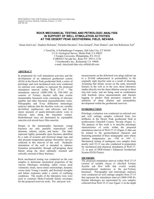
Rock Mechanical Testing and Petrologic Analysis in Support of Well ...
Rock Mechanical Testing and Petrologic Analysis in Support of Well ...
Rock Mechanical Testing and Petrologic Analysis in Support of Well ...

You also want an ePaper? Increase the reach of your titles
YUMPU automatically turns print PDFs into web optimized ePapers that Google loves.
PROCEEDINGS, Thirty-Fifth Workshop on Geothermal Reservoir Eng<strong>in</strong>eer<strong>in</strong>g<br />
Stanford University, Stanford, California, February 1-3, 2010<br />
SGP-TR-188<br />
ROCK MECHANICAL TESTING AND PETROLOGIC ANALYSIS<br />
IN SUPPORT OF WELL STIMULATION ACTIVITIES<br />
AT THE DESERT PEAK GEOTHERMAL FIELD, NEVADA<br />
Susan Juch Lutz 1 , Stephen Hickman 2 , Nicholas Davatzes 3 , Ezra Zemach 4 , Peter Drakos 4 , <strong>and</strong> Ann Robertson-Tait 5<br />
1 TerraTek, A Schlumberger Company, Salt Lake City, UT 84104<br />
2 U.S. Geological Survey, Menlo Park, CA 94025<br />
3 Temple University, Philadelphia, PA 19122<br />
4 ORMAT Nevada Inc., Reno NV 89511-1136<br />
5 GeothermEx Inc., Richmond, CA 94806<br />
e-mail: slutz@salt-lake-city.oilfield.slb.com<br />
ABSTRACT<br />
In preparation for well stimulation activities <strong>and</strong> the<br />
development <strong>of</strong> an enhanced geothermal system<br />
(EGS) <strong>in</strong> the Desert Peak geothermal field, a series <strong>of</strong><br />
petrologic <strong>and</strong> rock mechanical tests were conducted<br />
on selected core samples to represent the proposed<br />
stimulation <strong>in</strong>terval with<strong>in</strong> <strong>Well</strong> 27-15. The<br />
stimulation <strong>in</strong>terval (3000-3500 ft; 930-1085 m)<br />
consists <strong>of</strong> Tertiary rhyolite tuffs that overlie<br />
metamorphic basement rocks consist<strong>in</strong>g <strong>of</strong> siliceous<br />
argillite <strong>and</strong> other fractured metasedimentary rocks.<br />
Petrographic <strong>and</strong> X-ray diffraction m<strong>in</strong>eralogic<br />
analyses <strong>in</strong>dicate that the rhyolitic rocks are variably<br />
devitrified, argillaceous, <strong>and</strong> siliceous; <strong>and</strong> host<br />
m<strong>in</strong>or amounts <strong>of</strong> quartz-dolomite-calcite ve<strong>in</strong>s <strong>in</strong><br />
siliceous units along the basement contact.<br />
Hydrothermal clays are dom<strong>in</strong>ated by exp<strong>and</strong>able<br />
smectite-rich mixed-layer illite-smectite.<br />
Deeper <strong>in</strong> the metamorphic basement, young<br />
fractures are only partially m<strong>in</strong>eralized with<br />
dolomite, siderite, calcite, <strong>and</strong> barite. The latter<br />
represent lightly permeable open fractures identified<br />
by a suite <strong>of</strong> acoustic <strong>and</strong> electrical image logs <strong>and</strong><br />
<strong>and</strong> pressure-temperature-sp<strong>in</strong>ner flowmeter surveys<br />
collected <strong>in</strong> this <strong>in</strong>terval <strong>of</strong> the well. Hydraulic<br />
stimulation <strong>of</strong> the well is <strong>in</strong>tended to enhance<br />
formation permeability through self-propp<strong>in</strong>g shear<br />
failure along the most optimally oriented <strong>and</strong><br />
critically stressed <strong>of</strong> these fractures.<br />
<strong>Rock</strong> mechanical test<strong>in</strong>g was conducted on the core<br />
samples to determ<strong>in</strong>e mechanical properties <strong>of</strong> the<br />
various lithologies <strong>in</strong>clud<strong>in</strong>g: radial versus axial<br />
volumetric stra<strong>in</strong>, stress-stra<strong>in</strong> relationships, dynamic<br />
versus static Young’s moduli, <strong>and</strong> frictional strengths<br />
<strong>and</strong> failure responses under a variety <strong>of</strong> conf<strong>in</strong><strong>in</strong>g<br />
conditions. The results <strong>of</strong> the laboratory tests were<br />
used to construct Mohr-Coulomb failure envelopes<br />
for the proposed reservoir rocks. Pre- <strong>and</strong> post- test<br />
measurements on the deformed core plugs <strong>in</strong>dicate up<br />
to a 20-fold enhancement <strong>in</strong> permeability <strong>in</strong> the<br />
orig<strong>in</strong>ally tight rhyolite units as a result <strong>of</strong> shear<strong>in</strong>g.<br />
Assum<strong>in</strong>g that failure occurs on the same structural<br />
features <strong>in</strong> the well as <strong>in</strong> the core, these laboratory<br />
studies directly test the shear dilation concept <strong>in</strong> these<br />
clay-rich rocks, <strong>and</strong> are be<strong>in</strong>g used <strong>in</strong> comb<strong>in</strong>ation<br />
with borehole stress measurements <strong>and</strong> fracture<br />
logg<strong>in</strong>g to predict fluid pressures required for<br />
<strong>in</strong>itiation <strong>of</strong> shear dilation <strong>and</strong> permeability<br />
development with<strong>in</strong> the geothermal reservoir.<br />
INTRODUCTION<br />
<strong>Petrologic</strong> evaluation was conducted on selected core<br />
<strong>and</strong> well cutt<strong>in</strong>gs samples collected from two<br />
drillholes <strong>in</strong> the Desert Peak geothermal field <strong>in</strong><br />
northwestern Churchill County, Nevada (Figure 1).<br />
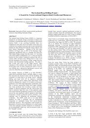
The purpose <strong>of</strong> this work is to describe petrologic<br />
characteristics <strong>of</strong> rocks with<strong>in</strong> the proposed<br />
stimulation <strong>in</strong>terval <strong>of</strong> <strong>Well</strong> 27-15 (Figure 2) that can<br />
be related to the geomechanical character <strong>and</strong><br />
fractur<strong>in</strong>g potential <strong>of</strong> these stratigraphic units where<br />
ambient temperatures are ~180 to 195° C.<br />
<strong>Mechanical</strong> test<strong>in</strong>g <strong>of</strong> analogous core samples from<br />
nearby well 35-13 was also conducted <strong>in</strong> preparation<br />
for mechanical <strong>and</strong> chemical stimulation <strong>of</strong> <strong>Well</strong> 27-<br />
15, as part <strong>of</strong> DOE-Ormat’s Enhanced Geothermal<br />
System (EGS) Project.<br />
METHODS<br />
The proposed stimulation <strong>in</strong>terval with<strong>in</strong> <strong>Well</strong> 27-15<br />
consists <strong>of</strong> variably clayey to silicified Tertiary<br />
rhyolite ash flow tuffs that overlie weakly<br />
metamorphosed mudstones <strong>in</strong> the pre-Tertiary<br />
basement. Petrographic <strong>and</strong> m<strong>in</strong>eralogic analyses<br />
were conducted on well cutt<strong>in</strong>gs samples from 27-15<br />
that represent the stimulation <strong>in</strong>terval (3000-3500 ft).<br />
Similar lithologies are represented by core samples<br />
collected from <strong>Well</strong> 35-13 (see Figure 1) <strong>in</strong> the depth
<strong>in</strong>terval from 2276 ft to 2742 ft. <strong>Mechanical</strong> test<strong>in</strong>g<br />
<strong>of</strong> these core samples was conducted at TerraTek.<br />
<strong>Petrologic</strong> Analyses<br />
The lithologies, composition, texture, ve<strong>in</strong> <strong>and</strong><br />
secondary m<strong>in</strong>eralogy <strong>of</strong> the represented rock units <strong>in</strong><br />
both 27-15 <strong>and</strong> 35-13 are based on th<strong>in</strong> section<br />
exam<strong>in</strong>ation, with semi-quantitative X-ray diffraction<br />
(XRD) analysis on match<strong>in</strong>g samples to better<br />
constra<strong>in</strong> rock m<strong>in</strong>eralogy <strong>and</strong> potentially<br />
problematic m<strong>in</strong>erals, such as exp<strong>and</strong>able clays. All<br />
sixteen <strong>of</strong> the core samples from 35-13 were<br />
analyzed by X-ray diffraction methods <strong>and</strong> prepared<br />
as th<strong>in</strong> sections, <strong>and</strong> <strong>of</strong> these, twelve samples were<br />
selected for petrographic description.<br />
For the 27-15 well cutt<strong>in</strong>gs, X-ray diffraction was<br />
conducted on samples collected every 20 ft<br />
throughout the 3000-3600 ft depth <strong>in</strong>terval, result<strong>in</strong>g<br />
<strong>in</strong> a total <strong>of</strong> thirty-one XRD samples. Of the thirtyone<br />
th<strong>in</strong> sections made, sixteen were selected for<br />
further petrographic analysis.<br />
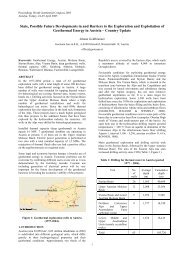
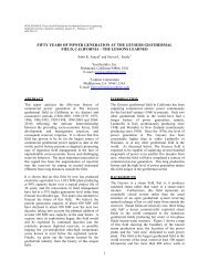
Figure 1: Location <strong>of</strong> wells <strong>in</strong> the Desert Peak<br />
geothermal field, most <strong>of</strong> the productive wells are<br />
located <strong>in</strong> Section 21. <strong>Well</strong>s circled <strong>in</strong> red represent<br />
previously studied wells (Lutz et al., 2009); those<br />
circled <strong>in</strong> green are wells <strong>in</strong> the current study. <strong>Well</strong><br />
27-15 is the planned EGS well. Core samples for the<br />
mechanical test<strong>in</strong>g are from <strong>Well</strong> 35-13. Surface<br />
fault traces <strong>in</strong> blue are based on mapp<strong>in</strong>g by Faulds<br />
<strong>and</strong> Garside (2003).<br />
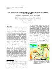
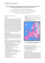
Figure 2: The planned stimulation <strong>in</strong>terval is between 3000 ft <strong>and</strong> 3500 ft (930-1085 m) <strong>in</strong> EGS <strong>Well</strong> 27-15; at the<br />
base <strong>of</strong> Tertiary Rhyolites <strong>and</strong> at the top <strong>of</strong> pre-Tertiary metasedimentary rocks (PT1) with<strong>in</strong> the metamorphic<br />
basement (modified from Lutz et al., 2009). <strong>Well</strong>s 22-22 <strong>and</strong> 21-2 are <strong>in</strong>jection wells; <strong>Well</strong>s 74-21, 77-21, <strong>and</strong> 21-1<br />
are active producers.
<strong>Rock</strong> <strong>Mechanical</strong> <strong>Test<strong>in</strong>g</strong><br />
<strong>Mechanical</strong> <strong>and</strong> petrophysical property analyses were<br />
conducted on selected core samples collected from<br />
<strong>Well</strong> 35-13. The test<strong>in</strong>g program consisted <strong>of</strong>:<br />
1) Cont<strong>in</strong>uous strength pr<strong>of</strong>il<strong>in</strong>g <strong>of</strong> all rock types<br />
with<strong>in</strong> the core segments us<strong>in</strong>g TSI scratch test<strong>in</strong>g;<br />
2) Dra<strong>in</strong>ed triaxial compression test<strong>in</strong>g on suites <strong>of</strong><br />
room temperature vertical samples for Mohr-<br />
Coulomb failure envelope del<strong>in</strong>eation with<br />
simultaneous ultrasonic velocity measurements; <strong>and</strong><br />
3) Basic petrophysical properties (i.e., porosity <strong>and</strong><br />
permeability at ambient stress conditions).<br />
For this test program, Ormat provided sixteen core<br />
sections from various depths with<strong>in</strong> <strong>Well</strong> 35-13. The<br />
purpose <strong>of</strong> the test<strong>in</strong>g was as follows:<br />
1) To provide an overall assessment <strong>of</strong> heterogeneity<br />
<strong>in</strong> rock strength us<strong>in</strong>g scratch test<strong>in</strong>g (TSI).<br />
2) To provide strength <strong>and</strong> rock physics <strong>in</strong>formation<br />
for develop<strong>in</strong>g a failure model for the material. With<br />
adequate measurements <strong>of</strong> strength on core samples,<br />
<strong>and</strong> with the availability <strong>of</strong> supplementary<br />
<strong>in</strong>formation such as clay content, sonic velocity <strong>and</strong><br />
porosity, logg<strong>in</strong>g-based predictions <strong>of</strong> <strong>in</strong>-situ strength<br />
may be possible. With such <strong>in</strong>formation, predictions<br />
<strong>of</strong> borehole stability <strong>and</strong> stress conditions can be<br />
performed.<br />
3) To provide static <strong>and</strong> dynamic mechanical<br />
properties that can be used <strong>in</strong> concert with well logs<br />
for predict<strong>in</strong>g reservoir response dur<strong>in</strong>g hydraulic<br />
stimulation <strong>and</strong> <strong>in</strong>jection/production <strong>and</strong> for creat<strong>in</strong>g<br />
3-D stress models (e.g., Davatzes <strong>and</strong> Hickman,<br />
2006). Physical/mechanical response <strong>of</strong> a material is<br />
dependent on the rate at which it is loaded <strong>and</strong> the<br />
applied stress/stra<strong>in</strong> amplitude. Logg<strong>in</strong>g-based<br />
measurements are <strong>in</strong> the kilohertz range; whereas<br />
actual physical load<strong>in</strong>g rates act<strong>in</strong>g on a wellbore <strong>and</strong><br />
<strong>in</strong> the reservoir are generally much slower (pseudostatic).<br />
We conducted laboratory pseudo-static<br />
test<strong>in</strong>g for measurement <strong>of</strong> Young’s modulus (E) <strong>and</strong><br />
Poisson’s ratio (n) while simultaneously measur<strong>in</strong>g<br />
dynamic (high load<strong>in</strong>g rate <strong>and</strong> low load<strong>in</strong>g<br />
magnitude) responses <strong>of</strong> core samples. These<br />
parameters provide <strong>in</strong>formation for well-log<br />
calibration, to provide realistic deformation<br />
parameters (E, n) for the eng<strong>in</strong>eer<strong>in</strong>g <strong>and</strong> design <strong>of</strong><br />
hydraulic fractur<strong>in</strong>g <strong>and</strong> other well stimulation <strong>and</strong><br />
production activities.<br />
PETROLOGIC DESCRIPTION<br />
In the two study wells, the basic lithologies with<strong>in</strong><br />
the basal part <strong>of</strong> the rhyolite sequence <strong>and</strong> at top <strong>of</strong><br />
the metamorphic basement are similar (Table 1).<br />
Three major types <strong>of</strong> rhyolite tuffs are identified<br />
based on the degree <strong>of</strong> devitrification <strong>and</strong> type <strong>of</strong><br />
secondary or hydrothermal alteration: devitrified,<br />
argillic, <strong>and</strong> siliceous. Metamorphic rocks generally<br />
consist <strong>of</strong> two endmember rock types that are<br />
gradational <strong>in</strong> m<strong>in</strong>eralogic composition <strong>and</strong> <strong>in</strong> degree<br />
Table 1. Lithologic Correlation for <strong>Rock</strong><br />
Mechanics <strong>Test<strong>in</strong>g</strong><br />
<strong>Well</strong> 35-13<br />
Test<br />
Sample<br />
No.<br />
<strong>Well</strong> 35-13<br />
Depth<br />
Interval<br />
(ft)<br />
ODP1 2286<br />
ODP2 2376<br />
ODP3 2392<br />
ODP4 2437<br />
ODP5 2483<br />
ODP6 2579<br />
ODP12 2591<br />
ODP13 2624<br />
ODP7 2741<br />
General<br />
Lithotype<br />
devitrified<br />
rhyolite<br />
argillic rhyolite<br />
siliceous<br />
rhyolite<br />
illitic/siliceous<br />
metamudstone<br />
siliceous<br />
metamudstone<br />
Equivalent<br />
depth(s) for<br />
these lithotypes<br />
<strong>in</strong> <strong>Well</strong> 27-15<br />
(ft)<br />
3040-3070<br />
3000-3030,<br />
3080-3090<br />
3100-3290<br />
3540-3590<br />
3600-3610<br />
<strong>of</strong> metamorphic foliation, <strong>and</strong> are classified as either<br />
illitic/siliceous metamudstone or siliceous<br />
metamudstone.<br />
Rhyolite Lithotypes<br />
In less altered rhyolites, relict shard texture with<br />
fiamme or flattened pumice fragments clearly<br />
identifies ash flow tuffs. Flow-b<strong>and</strong><strong>in</strong>g <strong>in</strong> rhyolitic<br />
glass <strong>and</strong> spherulitic devitrification characterize<br />
<strong>in</strong>dividual tuff units <strong>in</strong> more strongly welded tuffs.<br />
Some <strong>of</strong> the tuffs conta<strong>in</strong> resorbed <strong>and</strong> embayed<br />
quartz <strong>and</strong> sanid<strong>in</strong>e crystals, but most <strong>of</strong> the<br />
plagioclase phenocrysts are replaced by f<strong>in</strong>e quartz<br />
<strong>and</strong> clay m<strong>in</strong>erals. Relatively unaltered, devitrified<br />
rhyolite has about 40% quartz <strong>and</strong> 20% potassium<br />
feldspar, <strong>and</strong> variable amounts <strong>of</strong> plagioclase<br />
depend<strong>in</strong>g upon the orig<strong>in</strong>al crystal content (up to<br />
about 20%) <strong>and</strong> the extent <strong>of</strong> plagioclase alteration.<br />
In argillic rhyolite, much <strong>of</strong> the potassium feldspar<br />
formed by devitrification <strong>of</strong> the orig<strong>in</strong>al volcanic<br />
glass is further altered to clay m<strong>in</strong>erals. In <strong>Well</strong> 27-<br />
15, the rhyolite at 3080-3090 ft is argillically-altered<br />
<strong>and</strong> has 32% quartz <strong>and</strong> 32% total clay; 26% <strong>of</strong> the<br />
whole rock composition consists <strong>of</strong> illite. In <strong>Well</strong><br />
35-13, Samples ODP2 <strong>and</strong> ODP3 (2376 <strong>and</strong> 2392 ft)<br />
have 36-37% quartz <strong>and</strong> 31-43% total clay. These<br />
samples only have 3-4% potassium feldspar<br />
rema<strong>in</strong><strong>in</strong>g <strong>in</strong> the strongly clay-altered rhyolite. <strong>Well</strong><br />
35-13 is several miles from the ma<strong>in</strong> geothermal area<br />
(Figure 1) <strong>and</strong> the correspond<strong>in</strong>g core <strong>in</strong>terval is also<br />
about 1000 ft shallower than <strong>in</strong> <strong>Well</strong> 27-15, so the<br />
clays are less thermally mature. Clay m<strong>in</strong>erals <strong>in</strong> the<br />
core samples from 35-13 are dom<strong>in</strong>ated by smectite<br />
(5-14%) <strong>and</strong> smectite-rich illite-smectite (5-11%). In
3% pyrite <strong>in</strong> the silicified rock. Chemical dissolution<br />
<strong>of</strong> these carbonate-filled ve<strong>in</strong>s could potentially<br />
enhance permeability <strong>in</strong> these relatively tight<br />
siliceous rhyolites (Xu et al, 2009).<br />
Figure 3: XRD m<strong>in</strong>eralogy <strong>of</strong> well cutt<strong>in</strong>gs samples<br />
<strong>in</strong> the proposed stimulation <strong>in</strong>terval <strong>of</strong> <strong>Well</strong> 27-15 (<strong>in</strong><br />
relative weight percent). The contact between<br />
overly<strong>in</strong>g Tertiary rhyolites <strong>and</strong> the metamorphic<br />
basement occurs at a depth <strong>of</strong> approximately 3300 ft.<br />
<strong>Well</strong> 27-15, layers <strong>of</strong> clay alteration along bedd<strong>in</strong>g<br />
planes are easily identified as highly conductive<br />
planar features <strong>in</strong> Formation Microscanner (FMS)<br />
images (Kovac et al., 2009).<br />
The most siliceous rhyolites are comprised <strong>of</strong> 40-<br />
50% quartz, <strong>and</strong> are represented at depths <strong>of</strong> 3100-<br />
3280 ft <strong>in</strong> <strong>Well</strong> 27-15, <strong>and</strong> 2437-2530 ft <strong>in</strong> <strong>Well</strong> 35-<br />
13. In the upper parts <strong>of</strong> these zones, the rocks are<br />
generally dense <strong>and</strong> non-brecciated. With <strong>in</strong>creas<strong>in</strong>g<br />
depth <strong>in</strong> 27-15, the tuffaceous units are more<br />
silicified <strong>and</strong> have f<strong>in</strong>e quartz ve<strong>in</strong>lets that cut across<br />
the rock. In 35-13, most <strong>of</strong> the rhyolite core samples<br />
are densely welded, siliceous tuffs without abundant<br />
ve<strong>in</strong>s; samples ODP4, 5, <strong>and</strong> 9 (2437-2530 ft) are<br />
especially uniform <strong>in</strong> overall texture. XRD analyses<br />
<strong>in</strong>dicate a rather homogenous composition <strong>in</strong> this<br />
<strong>in</strong>terval with 40-43% quartz, 23-31% potassium<br />
feldspar, 8-12% plagioclase, <strong>and</strong> 16-19% clay.<br />
In <strong>Well</strong> 27-15, the base <strong>of</strong> the rhyolite sequence is<br />
highly silicified <strong>and</strong> recrystallized, <strong>and</strong> orig<strong>in</strong>al<br />
tuffaceous textures are generally obscured. The<br />
phyllic hydrothermal alteration assemblage consists<br />
<strong>of</strong> pervasive quartz, potassium feldspar, illite, <strong>and</strong><br />
pyrite. FMS images <strong>in</strong> this well exhibit an absence <strong>of</strong><br />
bedd<strong>in</strong>g planes <strong>in</strong> the 3190-3300 ft <strong>in</strong>terval (Kovac et<br />
al., 2009), but the presence <strong>of</strong> several m<strong>in</strong>or flow<strong>in</strong>g<br />
fractures are identified by temperature <strong>and</strong> sp<strong>in</strong>ner<br />
flowmeter surveys (Davatzes <strong>and</strong> Hickman, 2009).<br />
In th<strong>in</strong> section, thicker (0.5 mm) ve<strong>in</strong>s are filled with<br />
blocky calcite <strong>and</strong> have just a th<strong>in</strong> selvage <strong>of</strong><br />
prismatic quartz crystals. XRD analysis <strong>of</strong> the 27-15<br />
well cutt<strong>in</strong>gs from 3280-3290 ft <strong>in</strong>dicates up to 5%<br />
calcite ve<strong>in</strong>s <strong>and</strong> 2% dolomite alteration, as well as<br />
Basement Lithologies<br />
The upper part <strong>of</strong> the basement with<strong>in</strong> the planned<br />
stimulation <strong>in</strong>terval <strong>of</strong> <strong>Well</strong> 27-15 consists <strong>of</strong><br />
moderately metamorphosed hematitic mudstones<br />
associated with the Jurassic Humboldt Igneous<br />
Complex <strong>and</strong> underly<strong>in</strong>g lower Jurassic <strong>and</strong> upper<br />
Triassic metasediments. In <strong>Well</strong> 35-13, basement<br />
lithologies are more typical <strong>of</strong> the Pre-Tertiary 1<br />
(PT1) package <strong>of</strong> weakly metamorphosed siliceous<br />
shales, dolomudstones <strong>and</strong> metatuffs described from<br />
other wells to the north <strong>and</strong> east <strong>of</strong> the Desert Peak<br />
production area (Lutz et al., 2003; 2004; 2009).<br />
XRD analysis <strong>of</strong> the 35-13 core samples <strong>in</strong>dicates a<br />
fairly uniform m<strong>in</strong>eralogical composition with 42-<br />
55% quartz <strong>and</strong> 28-42% clay <strong>in</strong> illitic/siliceous<br />
metamudstones. The contact between overly<strong>in</strong>g<br />
Tertiary tuffs <strong>and</strong> the metamorphic basement occurs<br />
at about 3300 ft <strong>in</strong> <strong>Well</strong> 27-15, <strong>and</strong> between 2579.8 ft<br />
<strong>and</strong> 2587.0 ft <strong>in</strong> <strong>Well</strong> 35-13.<br />
The top <strong>of</strong> the basement <strong>in</strong> <strong>Well</strong> 27-15 (3320-3350 ft)<br />
consists <strong>of</strong> biotite schist <strong>and</strong> biotite-rich metavolcanic<br />
rocks. The cutt<strong>in</strong>gs are composed <strong>of</strong> large folded<br />
biotite, quartz, <strong>and</strong> plagioclase crystals with<strong>in</strong> a<br />
highly deformed chloritic <strong>and</strong> hematitic matrix. In<br />
XRD (Figure 3), the <strong>in</strong>crease <strong>in</strong> overall chlorite<br />
content (from 1-2% <strong>in</strong> the rhyolite, up to 6-16% <strong>in</strong><br />
deeper samples) is an <strong>in</strong>dication that metamorphic<br />
rocks <strong>in</strong> the basement have been transected by the<br />
well. Iron <strong>and</strong> titanium oxide m<strong>in</strong>eralization consists<br />
<strong>of</strong> magnetite (1%), hematite (2-4%), <strong>and</strong> anatase<br />
(2%).<br />
Below 3360 ft <strong>in</strong> <strong>Well</strong> 27-15, the metamorphic rocks<br />
are less deformed <strong>and</strong> more f<strong>in</strong>e-gra<strong>in</strong>ed <strong>and</strong><br />
siliceous, but are still strongly m<strong>in</strong>eralized with<br />
hematite. Between 3360 ft <strong>and</strong> 3480 ft, the rocks are<br />
fairly massive hematitic mudstones composed <strong>of</strong> 35-<br />
40% quartz, less than 10% feldspar, up to 4%<br />
hematite, 37-50% total clay, <strong>and</strong> with trace amounts<br />
<strong>of</strong> carbonate <strong>and</strong> amphibole m<strong>in</strong>erals. At 3480-3520<br />
ft, the hematitic mudstones exhibit some fault gouge<br />
development <strong>in</strong> the cutt<strong>in</strong>gs, <strong>and</strong> there is a lithologic<br />
change to more siliceous <strong>and</strong> pyritic mudstones<br />
below. These siliceous mudstones are composed <strong>of</strong><br />
up to 50% quartz <strong>and</strong> 34% illitic clay. The cutt<strong>in</strong>g<br />
samples from 3520 to 3600 ft are generally more<br />
foliated than the overly<strong>in</strong>g hematitic mudstones.<br />
Aligned muscovite plates <strong>and</strong> f<strong>in</strong>ely crystall<strong>in</strong>e illite<br />
exhibit weak to moderate foliation <strong>in</strong> these pelitic<br />
rocks.<br />
Thrust faults <strong>and</strong> other Mesozoic-aged faults<br />
complicate the basement stratigraphy. The FMS<br />
images show strong foliation <strong>in</strong> the metamudstones
<strong>and</strong> dramatic changes <strong>in</strong> foliation orientations across<br />
formation contacts, <strong>in</strong>dicat<strong>in</strong>g extensive fold<strong>in</strong>g or<br />
fault<strong>in</strong>g <strong>in</strong> this section <strong>of</strong> the well (Kovac et al.,<br />
2009). Temperature <strong>and</strong> sp<strong>in</strong>ner flowmeter surveys<br />
reveal the presence <strong>of</strong> relatively permeable fractures<br />
that are well oriented for normal fault<strong>in</strong>g, <strong>in</strong> addition<br />
to fluid flow that is preferentially developed along<br />
formation boundaries (Davatzes <strong>and</strong> Hickman, 2009;<br />
Hickman <strong>and</strong> Davatzes, 2010).<br />
PETROLOGIC EFFECTS ON MECHANICAL<br />
CHARACTER<br />
Texture <strong>and</strong> Strength<br />
Laboratory test<strong>in</strong>g <strong>of</strong> the <strong>Well</strong> 35-13 core samples<br />
reveals variable strengths <strong>and</strong> a range <strong>of</strong> other<br />
mechanical properties for the different lithologies. In<br />
the rhyolites, the character <strong>of</strong> the tuffaceous matrix<br />
controls the overall mechanical characteristics <strong>of</strong> the<br />
rock. In the basement rocks, the degree <strong>of</strong><br />
metamorphic foliation <strong>and</strong> the fractur<strong>in</strong>g <strong>in</strong>tensity<br />
controls the mechanical behavior.<br />
Overall, the evaluated rhyolite samples exhibit high<br />
porosity but poor permeability with<strong>in</strong> the devitrified<br />
<strong>and</strong> microporous tuffaceous matrices (Table 2). In<br />
the meta-sedimentary rocks, the dense siliceous<br />
matrix is less porous, <strong>and</strong> open fractures are the<br />
dom<strong>in</strong>ant pore type. M<strong>in</strong>eralogic <strong>and</strong> textural<br />
characteristics revealed by the petrologic analyses<br />
have strong effects on the mechanical behavior.<br />
These characteristics are discussed below:<br />
‣ Matrix Composition – This is likely the s<strong>in</strong>gle<br />
most important control on overall rock strength.<br />
Whether the rock is a siliceous rhyolite or a<br />
siliceous metasedimentary rock, it is the quartz<br />
content <strong>in</strong> the matrix that cements the matrix <strong>and</strong><br />
supports the rock under a variety <strong>of</strong> conf<strong>in</strong><strong>in</strong>g<br />
pressures. Results <strong>of</strong> the triaxial test<strong>in</strong>g <strong>in</strong>dicate<br />
that the most siliceous rhyolites <strong>and</strong><br />
metasedimentary rocks have the highest rock<br />
cohesion <strong>and</strong> overall strength (Tables 3 <strong>and</strong> 4).<br />
In contrast, the devitrified <strong>and</strong> argillaceous<br />
rhyolites with abundant potassium feldspar <strong>and</strong><br />
smectite-rich illite-smectite <strong>in</strong> the matrix exhibit<br />
lower rock strengths.<br />
‣ Matrix Fabric – In the rhyolites, silicification <strong>and</strong><br />
pervasive spherulitic devitrification is associated<br />
with higher cohesive strengths (Table 4)<br />
presumably because the spherules <strong>in</strong>hibit<br />
compaction <strong>and</strong> the formation <strong>of</strong> clayey lam<strong>in</strong>ae<br />
that could act as planes <strong>of</strong> weakness under<br />
compressive stress. The rounded spherule<br />
morphology should absorb stress, <strong>in</strong>crease<br />
contact surface areas, <strong>and</strong> limit gra<strong>in</strong>-scale<br />
microcrack<strong>in</strong>g <strong>and</strong> cataclastic pore collapse. The<br />
matrix <strong>in</strong> these dense silicified units is typically<br />
massive or homogeneous without well-def<strong>in</strong>ed<br />
bedd<strong>in</strong>g breaks. Where larger pumice fragments<br />
are compressed <strong>and</strong> flattened along bedd<strong>in</strong>g<br />
planes, or where the ash flow tuffs are more<br />
clay-altered or flow-b<strong>and</strong>ed, matrix microtexture<br />
is more heterogeneous <strong>and</strong> could be more prone<br />
to cataclasis <strong>and</strong> pore compaction.<br />
‣ In the metamorphic rocks, pre-exist<strong>in</strong>g foliation<br />
planes, m<strong>in</strong>eralogical differentiation, <strong>and</strong> older<br />
<strong>in</strong>tersect<strong>in</strong>g ve<strong>in</strong>s create a network <strong>of</strong> planar<br />
features with aligned <strong>and</strong> segregated micas, illitic<br />
clays, <strong>and</strong> other weak phyllosilicates that are<br />
more likely to fail under relatively low shear<br />
stress than more homogenous rocks with a more<br />
r<strong>and</strong>om microstructure.<br />
‣ Crystal <strong>and</strong> Clast Content – The ash flow tuffs<br />
are generally crystal-poor, but there are great<br />
contrasts <strong>in</strong> strength <strong>and</strong> other elastic properties<br />
between the microporous ashy matrix <strong>and</strong><br />
adjacent blocky plagioclase <strong>and</strong> quartz<br />
phenocrysts. As <strong>in</strong> tuff agglomerates or<br />
conglomerates, failure planes typically wrap<br />
around harder clasts or crystals <strong>in</strong> the core plugs<br />
(e.g., Figure 5 below). Although the<br />
metamorphic rocks are well cemented, the<br />
volcaniclastic metamudstones have similar large<br />
clasts embedded <strong>in</strong> a f<strong>in</strong>e matrix, creat<strong>in</strong>g<br />
strength heterogeneities <strong>in</strong> these rocks as well.<br />
‣ Ductile Gra<strong>in</strong>s <strong>and</strong> Clays - Comparatively s<strong>of</strong>t<br />
detrital components such as tuffaceous particles,<br />
dissolved or devitrified volcanic rock fragments,<br />
biotite <strong>and</strong> other detrital or metamorphic micas,<br />
as well as authigenic clays are abundant <strong>in</strong> both<br />
the volcanic <strong>and</strong> metasedimentary rocks.<br />
Authigenic kaol<strong>in</strong>ite <strong>and</strong> illite-smectite clays are<br />
especially abundant <strong>in</strong> the matrix <strong>of</strong> the<br />
tuffaceous rocks. These clays could lead to<br />
<strong>in</strong>creas<strong>in</strong>g compressibility <strong>in</strong> the more<br />
argillaceous rhyolites, <strong>and</strong> ductile deformation or<br />
clay smear<strong>in</strong>g dur<strong>in</strong>g shear failure (see Figure 5).<br />
The type <strong>of</strong> clay also affects the mechanical<br />
character; <strong>in</strong> that smectite-rich clays are weaker<br />
<strong>and</strong> smear more easily than illite or chlorite clays<br />
(Lockner <strong>and</strong> Beeler, 2002).<br />
‣ Ve<strong>in</strong> M<strong>in</strong>eralogy <strong>and</strong> Fracture Intensity - In the<br />
rhyolites, densely silicified rocks along the<br />
basement contact have crosscutt<strong>in</strong>g f<strong>in</strong>e quartz<br />
ve<strong>in</strong>lets. These are mostly sealed <strong>and</strong> probably<br />
help support the rocks aga<strong>in</strong>st compressive<br />
stress, but a few <strong>of</strong> the larger ve<strong>in</strong>s are filled with<br />
poorly cohesive late-stage calcite or have m<strong>in</strong>or<br />
open fracture porosity <strong>in</strong> the centers <strong>of</strong> the quartz<br />
ve<strong>in</strong>s. The latter could act as planes <strong>of</strong><br />
weakness, <strong>and</strong> if hydraulically stimulated could<br />
<strong>in</strong>crease permeability <strong>in</strong> these tight rocks.<br />
The metamorphic rocks are fractured, especially<br />
along the previously eroded top <strong>of</strong> the basement,
<strong>and</strong> possibly along older faults between different<br />
metasedimentary packages. In <strong>Well</strong> 35-13, some<br />
<strong>of</strong> the fractures are filled with low temperature<br />
carbonates (siderite, dolomite, calcite) <strong>and</strong> barite,<br />
but many <strong>of</strong> the core pieces have extensive open<br />
fractures. The mechanical tests were conducted<br />
on the least fractured core pieces, but these also<br />
show failure planes along pre-exist<strong>in</strong>g planar<br />
features such as older ve<strong>in</strong>s.<br />
‣ Primary/Secondary Porosity – The devitrified<br />
<strong>and</strong> argillaceous rhyolites are much more porous<br />
<strong>and</strong> permeable than the siliceous tuffs. The<br />
porosity is dom<strong>in</strong>ated by matrix micropores<br />
between very f<strong>in</strong>ely crystall<strong>in</strong>e quartz, potassium<br />
feldspar, <strong>and</strong> clay particles <strong>in</strong> the devitrified<br />
matrix. Devitrification spherules are especially<br />
permeable because the rock matrix is not<br />
compacted <strong>and</strong> the micropores are wellconnected<br />
<strong>in</strong> a radial pattern between the f<strong>in</strong>e<br />
crystallites. In the dense siliceous rhyolites, the<br />
matrix is cemented by clots <strong>of</strong> quartz crystals<br />
<strong>and</strong> quartz-replaced pumice fragments, <strong>and</strong><br />
permeability values are much lower (Table 2).<br />
Many <strong>of</strong> the matrix micropores are also clogged<br />
with authigenic kaol<strong>in</strong>ite <strong>and</strong> clayey or cherty<br />
pseudomatrix. The porous <strong>and</strong> permeable<br />
devitrified <strong>and</strong> argillaceous rhyolites have less<br />
silica to support the rock framework <strong>and</strong> exhibit<br />
lower <strong>in</strong>tact rock strengths than the more<br />
siliceous rhyolites (Table 4).<br />
RESULTS OF MECHANICAL TESTING<br />
Triaxial compression tests were conducted on cores<br />
from <strong>Well</strong> 35-13 us<strong>in</strong>g a servo-controlled test<strong>in</strong>g<br />
apparatus which subjected the samples to the desired<br />
stress states at controlled stra<strong>in</strong> rates. Prior to test<strong>in</strong>g,<br />
each test sample was placed between two end-caps<br />
<strong>and</strong> jacketed with either a Teflon® or polyolef<strong>in</strong><br />
sleeve. The jacketed test specimen was then<br />
<strong>in</strong>strumented with axial <strong>and</strong> radial cantilevers for<br />
stra<strong>in</strong> measurement <strong>and</strong> <strong>in</strong>stalled <strong>in</strong> the pressure<br />
vessel for test<strong>in</strong>g.<br />
For failure characterization, suites <strong>of</strong> s<strong>in</strong>gle-stage<br />
triaxial compression tests were conducted on vertical<br />
samples (i.e., samples aligned parallel to the borehole<br />
axis) <strong>in</strong> order to construct Mohr stress circles <strong>and</strong><br />
calculate Coulomb parameters for both peak<br />
compressive strength correspond<strong>in</strong>g to <strong>in</strong>itial failure<br />
<strong>of</strong> the <strong>in</strong>tact rock, <strong>and</strong> residual effective compressive<br />
strength correspond<strong>in</strong>g to quasi-stable frictional<br />
slid<strong>in</strong>g on the newly formed fracture at the end <strong>of</strong><br />
each test. Triaxial compression tests were performed<br />
with air as the pore fluid <strong>and</strong> pore pressure dra<strong>in</strong>ed to<br />
the atmosphere. Results <strong>of</strong> triaxial compression tests<br />
<strong>and</strong> residual strengths, <strong>in</strong>clud<strong>in</strong>g quasi-static<br />
mechanical properties, are summarized for the three<br />
most dom<strong>in</strong>ant lithologies <strong>in</strong> Table 3. Summary plots<br />
for the failure characterization <strong>in</strong> devitrified versus<br />
siliceous rhyolites are shown <strong>in</strong> Figure 4.<br />
Dynamic mechanical properties us<strong>in</strong>g ultrasonic<br />
wave transmission (with 1MHz P- <strong>and</strong> S-wave<br />
transducers) were determ<strong>in</strong>ed concurrently with all<br />
triaxial compression tests. Ultrasonic velocities <strong>and</strong><br />
dynamic mechanical properties (Young’s modulus<br />
<strong>and</strong> Poisson’s ratio) were also determ<strong>in</strong>ed for the 35-<br />
13 core samples (Table 3).<br />
Scratch tests were also conducted along the length <strong>of</strong><br />
the core segments us<strong>in</strong>g TSI scratch test<strong>in</strong>g<br />
apparatus to provide semi-quantitative, empirical<br />
<strong>in</strong>formation on variations <strong>in</strong> unconf<strong>in</strong>ed compressive<br />
strength with lithology <strong>and</strong> extent <strong>of</strong> ve<strong>in</strong><strong>in</strong>g. More<br />
details on all the tests conducted on the core samples<br />
from <strong>Well</strong> 35-13 can be found <strong>in</strong> TerraTek Report<br />
TR09-402855 (TerraTek, 2009).<br />
SUMMARY OF MECHANICAL PROPERTIES<br />
BY LITHOTYPE<br />
The follow<strong>in</strong>g tables list representative test results<br />
from the rout<strong>in</strong>e core analyses, uniaxial or<br />
unconf<strong>in</strong>ed compression stress tests (UCS) from the<br />
TSI scratch test<strong>in</strong>g, triaxial compression tests, <strong>and</strong><br />
Mohr-Coulomb failure evaluations for general<br />
lithotypes with<strong>in</strong> the studied <strong>in</strong>terval <strong>of</strong> <strong>Well</strong> 35-13.<br />
Table 2 presents porosity <strong>and</strong> permeability<br />
relationships for selected samples, <strong>and</strong> Tables 3 <strong>and</strong> 4<br />
represent a summary <strong>of</strong> the scratch test<strong>in</strong>g <strong>and</strong><br />
triaxial compression test results along with derived<br />
parameters for the Mohr-Coulomb failure envelopes.<br />
In Table 4, the <strong>in</strong>ternal friction angles <strong>and</strong> <strong>in</strong>ternal<br />
l<strong>in</strong>ear cohesions are calculated by fitt<strong>in</strong>g a tangential<br />
l<strong>in</strong>e to the population <strong>of</strong> Mohr circles def<strong>in</strong>ed at the<br />
peak axial stresses at <strong>in</strong>itial failure for each conf<strong>in</strong><strong>in</strong>g<br />
pressure (the red circles <strong>in</strong> Figure 4). The residual<br />
friction angles <strong>and</strong> residual cohesions represent the<br />
tangents to Mohr circles def<strong>in</strong>ed from the f<strong>in</strong>al,<br />
quasi-stable axial stress at <strong>in</strong>itial failure for each<br />
conf<strong>in</strong><strong>in</strong>g pressure (the green circles <strong>in</strong> Figure 4).<br />
These residual friction angles, φ, are used to<br />
determ<strong>in</strong>e the coefficients <strong>of</strong> slid<strong>in</strong>g friction, µ from<br />
the expression µ = tan φ. Hickman <strong>and</strong> Davatzes<br />
(2010) use these slid<strong>in</strong>g friction values <strong>in</strong> concert<br />
with two end-member 3-D stress models to determ<strong>in</strong>e<br />
the propensity for frictional failure along fractures<br />
seen <strong>in</strong> the stimulation <strong>in</strong>terval from <strong>Well</strong> 27-15 as a<br />
function <strong>of</strong> excess fluid pressure. These calculations<br />
are be<strong>in</strong>g used to design optimal <strong>in</strong>jection parameters<br />
for hydraulic stimulation dur<strong>in</strong>g the Desert Peak EGS<br />
project. Note that the residual cohesions shown <strong>in</strong><br />
Table 4 are likely an artifact <strong>of</strong> the f<strong>in</strong>ite strength <strong>of</strong><br />
the jackets used to enclose these samples dur<strong>in</strong>g<br />
test<strong>in</strong>g, <strong>and</strong> thus should be neglected when<br />
calculat<strong>in</strong>g actual slid<strong>in</strong>g friction on pre-fractured<br />
rock.
Based on the results <strong>of</strong> compression strength test<strong>in</strong>g<br />
at a series <strong>of</strong> conf<strong>in</strong><strong>in</strong>g pressures (1, 4, 10, <strong>and</strong> 20<br />
MPa), the stiffer siliceous rhyolites display<br />
moderately high Young’s modulus values (Table 3).<br />
Although the metasedimentary rocks were tested at<br />
only two conf<strong>in</strong><strong>in</strong>g pressures (4 <strong>and</strong> 10 or 20 MPa)<br />
<strong>and</strong> the material properties are less well constra<strong>in</strong>ed,<br />
these siliceous rocks also display high Young’s<br />
moduli. The strongest rocks <strong>in</strong> the sample suite<br />
appear to be the unfractured or m<strong>in</strong>imally ve<strong>in</strong>ed<br />
siliceous rhyolites <strong>and</strong> siliceous metamudstones,<br />
although the metamorphic rocks generally have<br />
higher peak <strong>and</strong> residual cohesive strengths than the<br />
rhyolites (Table 4). Quasi-static values for Young’s<br />
modulus <strong>and</strong> Poisson’s ratio ranged from 6538 MPa<br />
(<strong>in</strong> argillaceous rhyolite) to 41,700 MPa (<strong>in</strong> siliceous<br />
metamudstone), <strong>and</strong> 0.08 to 0.24, respectively<br />
(TerraTek, 2009). The greatest <strong>in</strong>crease <strong>of</strong> Young’s<br />
modulus values with <strong>in</strong>creas<strong>in</strong>g conf<strong>in</strong><strong>in</strong>g pressures<br />
occurs with<strong>in</strong> argillic rhyolite. For example, for<br />
Sample ODP2 at 2376 ft, Young’s modulus is 6806<br />
MPa at an effective conf<strong>in</strong><strong>in</strong>g pressure <strong>of</strong> 1 MPa;<br />
whereas at 10 MPa, it is 17,920 MPa (TerraTek,<br />
2009). These weaker argillaceous rocks start out at<br />
low values <strong>of</strong> Young’s modulus <strong>and</strong> then appear to<br />
compact (become stiffer) at higher conf<strong>in</strong><strong>in</strong>g<br />
pressures, thereby <strong>in</strong>creas<strong>in</strong>g Young’s modulus.<br />
Such an effect is not seen <strong>in</strong> the already wellcemented<br />
siliceous rocks.<br />
Comparison <strong>of</strong> these data sets <strong>in</strong>dicates overall<br />
moderate rock strengths; with UCS estimates from<br />
TSI test<strong>in</strong>g <strong>of</strong> about 17,000-27,000 psi (117-186<br />
MPa) for the more siliceous lithologies, <strong>and</strong> about<br />
12,000-16,000 psi (82-110 MPa) for the argillaceous<br />
<strong>and</strong> devitrified rhyolites (Table 4). The devitrified<br />
<strong>and</strong> argillaceous rhyolites <strong>and</strong> illitic metasedimentary<br />
rocks have the highest <strong>in</strong>itial porosities, with up to<br />
21% porosity recorded for the devitrified rhyolites<br />
(Table 2). Comparison <strong>of</strong> somewhat spotty pre- <strong>and</strong><br />
post-test core data appears to <strong>in</strong>dicate up to a 20-fold<br />
<strong>in</strong>crease <strong>in</strong> permeability as a result <strong>of</strong> dilational<br />
failure <strong>in</strong> orig<strong>in</strong>ally tight (
Table 3. Summary <strong>of</strong> Triaxial Compression Tests for Selected Samples - Desert Peak 35-13<br />
Depth <strong>and</strong><br />
General<br />
Lithotype<br />
2286 ft<br />
devitrified<br />
rhyolite<br />
2437 ft<br />
siliceous<br />
rhyolite<br />
Sample<br />
ID<br />
As-<br />
Received<br />
Bulk<br />
Density<br />
(g/cm 3 )<br />
Effective<br />
Conf<strong>in</strong><strong>in</strong>g<br />
Pressure 1<br />
(MPa)<br />
Effective<br />
Compressive<br />
Strength<br />
(MPa)<br />
Residual<br />
Effective<br />
Compressive<br />
Strength<br />
(MPa)<br />
Quasi-<br />
Static<br />
Young’s<br />
Modulus<br />
(MPa)<br />
Quasi-<br />
Static<br />
Poisson’s<br />
Ratio<br />
ODP1-2 2.120 1 52.28 17.1 8510 0.15<br />
ODP1-5 2.086 4 55.43 26.7 6538 0.14<br />
ODP1-1 2.107 10 78.85 51.4 7819 0.17<br />
ODP1-4 2.106 20 105.04 81.3 8216 0.21<br />
ODP4-3 2.406 1 108.17 16.4 22,100 0.13<br />
ODP4-2 2.407 4 138.15 36.7 25,410 0.18<br />
ODP4-1 2.410 10 170.83 56.3 25,970 0.18<br />
ODP4-5 2.419 20 227.29 104.8 26,490 0.19<br />
2624 ft<br />
illitic/siliceous<br />
ODP13-2 2.711 4 132.31 47.6 30,340 0.40<br />
metamudstone ODP13-1 2.719 20 213.68 127.9 38,090 0.17<br />
1 Pore pressure = 0 psi <strong>in</strong> all tests<br />
Table 4. Calculated Unconf<strong>in</strong>ed Compressive Strength (UCS) <strong>and</strong> Mohr-Coulomb Properties<br />
<strong>Well</strong> 35-<br />
13 Test<br />
Sample<br />
<strong>and</strong><br />
Average<br />
Depth<br />
ODP1<br />
2286 ft<br />
ODP2<br />
2376 ft<br />
ODP3<br />
2392 ft<br />
ODP4<br />
2437 ft<br />
ODP5<br />
2483 ft<br />
ODP6<br />
2579 ft<br />
ODP12<br />
2591ft<br />
ODP13<br />
2624ft<br />
ODP7<br />
2741 ft<br />
General<br />
Lithotype<br />
devitrified<br />
rhyolite<br />
argillic<br />
rhyolite<br />
siliceous<br />
rhyolite<br />
illitic/siliceous<br />
metamudstone<br />
siliceous<br />
metamudstone<br />
Average UCS<br />
(as calculated<br />
from TSI<br />
tests)<br />
(psi)<br />
(MPa)<br />
Internal<br />
Friction<br />
Angle<br />
(degrees)<br />
Internal<br />
L<strong>in</strong>ear<br />
Cohesion<br />
(MPa)<br />
Mohr-Coulomb Properties<br />
Residual<br />
L<strong>in</strong>ear<br />
Cohesion<br />
(MPa)<br />
Residual<br />
Friction<br />
Angle<br />
(degrees)<br />
Coefficient<br />
<strong>of</strong> Slid<strong>in</strong>g<br />
Friction<br />
(µ)<br />
12,000 82.8 29.3 13.84 3.82 33.3 0.655<br />
16,000 110.3 35.4 10.02 3.63 35.2 0.704<br />
15,000 103.4 32.5 12.85 4.38 33.0 0.650<br />
26,000 179.3 45.9 21.86 3.31 39.6 0.827<br />
19,000 131.0 38.2 24.02 1.74 40.5 0.855<br />
17,000 117.2 47.6 19.23 0 43.9 0.962<br />
21,100 144.8 44.4 12.75 1.93 50.5 1.215<br />
27,000 186.2 42.2 24.83 6.13 41.9 0.898<br />
26,000 179.3 33.8 34.89 13.27 33.6 0.664
Axial Stress Difference, MPa<br />
120<br />
100<br />
80<br />
60<br />
40<br />
Effective Compressive Strength<br />
ODP1-2 (Vert), C o' = 52.28 MPa<br />
ODP1-5 (Vert), C o' = 55.43 MPa<br />
ODP1-1 (Vert), C o' = 78.85 MPa<br />
ODP1-4 (Vert), C o' = 105.04 MPa<br />
Pc = 20 MPa<br />
Pc = 10 MPa<br />
Pc = 4 MPa<br />
Axial Stress Difference, MPa<br />
240<br />
200<br />
160<br />
120<br />
80<br />
Effective Compressive Strength<br />
ODP4-3 (Vert), C o' = 108.17 MPa<br />
ODP4-2 (Vert), C o' = 138.15 MPa<br />
ODP4-1 (Vert), C o' = 170.83 MPa<br />
ODP4-5 (Vert), C o' = 227.29 MPa<br />
Pc = 20 MPa<br />
Pc = 10 MPa<br />
Pc = 4 MPa<br />
Pc = 1 MPa<br />
Pc = 1 MPa<br />
20<br />
40<br />
0<br />
-0.06 -0.04 -0.02 0 0.02 0.04 0.06<br />
(Radial) Stra<strong>in</strong> (Axial)<br />
0<br />
-0.08 -0.06 -0.04 -0.02 0 0.02 0.04 0.06 0.08<br />
(Radial) Stra<strong>in</strong> (Axial)<br />
Coulomb Failure Envelope - Ormat Desert Peak 35-13<br />
Depth 2285 ft<br />
Coulomb Failure Envelope - Ormat Desert Peak 35-13<br />
Depth 2437 ft<br />
80<br />
140<br />
Shear Stress, MPa<br />
70<br />
60<br />
50<br />
40<br />
30<br />
20<br />
Effective Compressive Strength<br />
Friction Angle = 29.3 o<br />
L<strong>in</strong>ear Cohesion = 13.84 MPa<br />
Effective Residual Compressive<br />
Strength<br />
Friction Angle = 33.2 o<br />
L<strong>in</strong>ear Cohesion = 3.82 MPa<br />
Shear Stress, MPa<br />
120<br />
100<br />
80<br />
60<br />
40<br />
Effective Compressive Strength<br />
Friction Angle = 45.9 o<br />
L<strong>in</strong>ear Cohesion = 21.86 MPa<br />
Effective Residual Compressive<br />
Strength<br />
Friction Angle = 39.6 o<br />
L<strong>in</strong>ear Cohesion = 3.31 MPa<br />
10<br />
20<br />
0<br />
0 20 40 60 80 100 120 140<br />
Effective Normal Stress, MPa<br />
0<br />
0 50 100 150 200 250<br />
Effective Normal Stress, MPa<br />
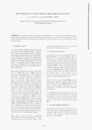
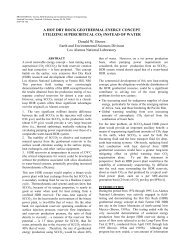
Figure 4. Comparison <strong>of</strong> failure behavior between devitrified, less stiff rhyolite at 2285 ft (left), <strong>and</strong> stonger, more<br />
siliceous rhyolite at 2437 ft (right). The upper plots show the results <strong>of</strong> triaxial compressive tests <strong>and</strong> the stressstra<strong>in</strong><br />
response for four vertical samples under conf<strong>in</strong><strong>in</strong>g pressures <strong>of</strong> 1, 4, 10 <strong>and</strong> 20 MPa. The effective<br />
compressive strength is <strong>in</strong>dicated for each test. The lower plots present Coulomb failure envelopes for the four<br />
vertical samples from each depth. Coulomb criteria (friction angle <strong>and</strong> l<strong>in</strong>ear cohesion) were determ<strong>in</strong>ed for two<br />
ranges – peak effective compressive strength (red) <strong>and</strong> effective residual compressive strength (green) for the entire<br />
test group. High residual cohesions are likely an effect <strong>of</strong> the plastic jackets on the fractured core plugs.
Figure 5. Multiple scales <strong>of</strong> observation <strong>of</strong> <strong>in</strong>duced failure planes produced dur<strong>in</strong>g triaxial compression test<strong>in</strong>g<br />
(conducted at conf<strong>in</strong><strong>in</strong>g pressures <strong>of</strong> 4MPa, similar to conditions at the proposed stimulation depths with<strong>in</strong> <strong>Well</strong> 27-<br />
15): a) jacketed post-test, fractured core plugs; b) CAT-scan images <strong>of</strong> these same core plugs, c) 3-D pr<strong>of</strong>il<strong>in</strong>g<br />
microscopy <strong>of</strong> the developed fracture planes, <strong>and</strong> d) scann<strong>in</strong>g electron microscope images <strong>of</strong> the failure surfaces.<br />
The images on the left represent devitrified rhyolite tuff (Sample ODP1) <strong>and</strong> show a curved fracture plane (b), welldeveloped<br />
slickensides <strong>in</strong> clayey material along the failure plane (c), <strong>and</strong> smeared clay over the highly microporous<br />
argillaceous matrix (d). The images to the right represent dense siliceous rhyolite tuff (Sample ODP4) that broke<br />
<strong>in</strong>to several straight fractures (b), <strong>and</strong> produced abundant quartz-rich rock flour (c <strong>and</strong> d) that could act to selfprop<br />
the newly created fracture with<strong>in</strong> the tight matrix.
CONCLUSIONS<br />
Most <strong>of</strong> the rocks <strong>in</strong> the proposed stimulation <strong>in</strong>terval<br />
with<strong>in</strong> <strong>Well</strong> 27-15 are moderately siliceous, f<strong>in</strong>egra<strong>in</strong>ed<br />
rocks. The clay content <strong>of</strong> the rhyolitic rocks<br />
<strong>and</strong> metamorphic mudstones is also moderately high<br />
<strong>and</strong> it is the clay m<strong>in</strong>eralogy that controls the porosity<br />
<strong>and</strong> texture <strong>of</strong> the matrix materials, while the<br />
siliceous m<strong>in</strong>eralogy supports the matrix <strong>and</strong><br />
<strong>in</strong>creases overall rock strength. The results <strong>of</strong> the<br />
mechanical test<strong>in</strong>g <strong>in</strong>dicate that these rocks are<br />
generally good c<strong>and</strong>idates for hydraulic stimulation.<br />
Other factors that may affect their behavior dur<strong>in</strong>g<br />
chemical or mechanical stimulation <strong>in</strong>clude<br />
heterogeneity related to ve<strong>in</strong>s, fractures, texture,<br />
temperature, pore pressures, <strong>and</strong> <strong>in</strong>-situ <strong>and</strong> tectonic<br />
stresses. Prelim<strong>in</strong>ary scann<strong>in</strong>g electron microscopic<br />
(SEM) exam<strong>in</strong>ation <strong>of</strong> the <strong>in</strong>duced failure planes<br />
created dur<strong>in</strong>g these mechanical tests <strong>in</strong>dicates that<br />
smectite-rich clays <strong>in</strong> the argillaceous rhyolites may<br />
deform ductilely under higher stress conditions.<br />
Thus. these planes l<strong>in</strong>ed with low cohesion clayey<br />
materials may act as planes <strong>of</strong> weakness to localize<br />
shear<strong>in</strong>g dur<strong>in</strong>g stimulation but are not expected to<br />
create significant, dilatant permeability <strong>in</strong> the rock.<br />
In contrast, brittle deformation <strong>in</strong> the more siliceous<br />
rocks is characterized by the production <strong>of</strong> quartzrich<br />
rock flour that may act as a proppant, preserv<strong>in</strong>g<br />
permeability along newly formed fractures after the<br />
hydraulic stimulation has ceased. This <strong>in</strong>terpretation<br />
is supported by high measured permeability ga<strong>in</strong>s <strong>and</strong><br />
observations <strong>of</strong> significant residual fracture porosity<br />
<strong>in</strong> these rocks follow<strong>in</strong>g shear<strong>in</strong>g.<br />
Coulomb failure calculations assum<strong>in</strong>g cohesionless<br />
pre-exist<strong>in</strong>g fractures with coefficients <strong>of</strong> friction <strong>of</strong><br />
0.6 or higher (consistent with the results <strong>of</strong> these core<br />
tests) <strong>in</strong>dicate that shear failure could be <strong>in</strong>duced on<br />
well-oriented fractures seen <strong>in</strong> <strong>Well</strong> 27-15 once fluid<br />
pressures are <strong>in</strong>creased above the ambient formation<br />
fluid pressure (Hickman <strong>and</strong> Davatzes, 2010). This<br />
geomechanical model will be tested dur<strong>in</strong>g hydraulic<br />
stimulation <strong>of</strong> well 27-15 as part <strong>of</strong> the Desert Peak<br />
EGS Project, which is <strong>in</strong>tended to enhance formation<br />
permeability through self-propp<strong>in</strong>g shear failure.<br />
Acknowledgements<br />
The Desert Peak EGS project is supported by the<br />
U.S. Department <strong>of</strong> Energy, Assistant Secretary for<br />
Energy Efficiency <strong>and</strong> Renewable Energy, under<br />
DOE Grant No. DE-FC36-02ID14406.<br />
REFERENCES<br />
Davatzes, N.C. <strong>and</strong> S. Hickman, 2006, Stress <strong>and</strong> fault<strong>in</strong>g <strong>in</strong> the<br />
Coso Geothermal Field: Update <strong>and</strong> recent results from the East<br />
Flank <strong>and</strong> Coso Wash: Proceed<strong>in</strong>gs, Thirty-First Workshop on<br />
Geothermal Reservoir Eng<strong>in</strong>eer<strong>in</strong>g, Stanford University, Stanford<br />
California, January 30-February 1, 2006 SGP-TR-179.<br />
Davatzes, N., <strong>and</strong> Hickman, S., 2009, Fractures, stress, <strong>and</strong> fluid<br />
flow prior to stimulation <strong>of</strong> <strong>Well</strong> 27-15, Desert Peak, Nevada, EGS<br />
Project: Proceed<strong>in</strong>gs, Thirty-Fourth Workshop on Geothermal<br />
Reservoir Eng<strong>in</strong>eer<strong>in</strong>g Stanford University, Stanford, California,<br />
February 9-11, 2009 SGP-TR-187.<br />
Faulds, J.E., <strong>and</strong> Garside, L.J., 2003, Prelim<strong>in</strong>ary geologic map <strong>of</strong><br />
the Desert Peak – Brady geothermal fields, Churchill County,<br />
Nevada: Nevada Bureau <strong>of</strong> M<strong>in</strong>es <strong>and</strong> Geology Open-File Report<br />
03-27.<br />
Faulds, J.E., Garside, L., <strong>and</strong> Oppliger, G.L., 2003, Structural<br />
analysis <strong>of</strong> the Desert Peak-Brady Geothermal Fields, northwestern<br />
Nevada: Implications for underst<strong>and</strong><strong>in</strong>g l<strong>in</strong>kages between<br />
northeast-trend<strong>in</strong>g structures <strong>and</strong> geothermal reservoirs <strong>in</strong> the<br />
Humboldt structural zone: Geothermal Resources Council<br />
Transactions, v. 27, p. 859-864.<br />
Hickman, S., <strong>and</strong> Davatzes, N., 2010, In-situ stress <strong>and</strong> fracture<br />
characterization for plann<strong>in</strong>g <strong>of</strong> an EGS stimulation <strong>in</strong> the Desert<br />
Peak geothermal field, NV: Proceed<strong>in</strong>gs, Thirty-fifth Workshop on<br />
Geothermal Reservoir Eng<strong>in</strong>eer<strong>in</strong>g Stanford University, Stanford,<br />
California, February 1-3, 2010 SGP-TR-188.<br />
Kovac, K., Lutz, S.J., Drakos, P. S., <strong>and</strong> Robertson-Tait, A., 2009,<br />
Borehole image analysis <strong>and</strong> geological <strong>in</strong>terpretation <strong>of</strong> selected<br />
features <strong>in</strong> <strong>Well</strong> DP 27-15 at Desert Peak, Nevada: Pre-stimulation<br />
evaluation <strong>of</strong> an Enhanced Geothermal System: Proceed<strong>in</strong>gs,<br />
Thirty-Fourth Workshop on Geothermal Reservoir Eng<strong>in</strong>eer<strong>in</strong>g<br />
Stanford University, Stanford, California, February 9-11, 2009<br />
SGP-TR-187.<br />
Lockner, D.A., <strong>and</strong> N.M. Beeler, 2002, Chapter 32, <strong>in</strong> International<br />
H<strong>and</strong>book <strong>of</strong> Earthquake <strong>and</strong> Eng<strong>in</strong>eer<strong>in</strong>g Seismology , edited by<br />
W.H.K. Lee, H. Kanamori, P.C. Jenn<strong>in</strong>gs, <strong>and</strong> C. Kissl<strong>in</strong>ger,<br />
Academic Press, Amsterdam, pp. 505-537.<br />
Lutz, S.J., A. Schriener Jr., D. Schochet <strong>and</strong> A. Robertson-Tait,<br />
2003. Geologic characterization <strong>of</strong> pre-Tertiary rocks at the Desert<br />
Peak East EGS project site, Churchill County, Nevada.<br />
Transactions, Geothermal Resources Council, Vol. 27, pp.865-870.<br />
Lutz, S.J., Robertson-Tait, A., <strong>and</strong> Morris, C.L., 2004,<br />
Stratigraphic relationships <strong>in</strong> Mesozoic basement rocks at the<br />
Desert Peak East EGS area, Nevada: Proceed<strong>in</strong>gs, Twenty-N<strong>in</strong>th<br />
Workshop on Geothermal Reservoir Eng<strong>in</strong>eer<strong>in</strong>g Stanford<br />
University, Stanford, California, January 26-28, 2004 SGP-TR-<br />
175.<br />
Lutz, S.J., Moore, J.N., Jones, C.G., Suemnicht, G., <strong>and</strong><br />
Robertson-Tait, A., 2009, Geological <strong>and</strong> structural relationships<br />
<strong>in</strong> the Desert Peak geothermal system, Nevada: Implications for<br />
EGS development: Proceed<strong>in</strong>gs, Thirty-fourth Workshop on<br />
Geothermal Reservoir Eng<strong>in</strong>eer<strong>in</strong>g Stanford University, Stanford,<br />
California, February 9-11, 2009 SGP-TR-187.<br />
TerraTek, 2009, Failure <strong>and</strong> Physical Characterization <strong>of</strong> Selected<br />
Materials: Desert Peak 35-13, Technical Report TR09-402855<br />
prepared for Ormat Nevada, November 2009, TerraTek- A<br />
Schlumberger Company, Salt Lake City, UT.<br />
Xu, T., Rose, P., Fayer, S. <strong>and</strong> Pruess, K., 2009, Numerical<br />
simulation study <strong>of</strong> silica <strong>and</strong> calcite dissolution around<br />
geothermal wells by <strong>in</strong>ject<strong>in</strong>g high pH solutions with chelat<strong>in</strong>g<br />
agent: Proceed<strong>in</strong>gs, Thirty-fourth Workshop on Geothermal<br />
Reservoir Eng<strong>in</strong>eer<strong>in</strong>g Stanford University, Stanford, California,<br />
February 9-11, 2009 SGP-TR-187.