Development of 0.5 MWe Scale DeSOX-DeNOX ... - Getreideheizung
Development of 0.5 MWe Scale DeSOX-DeNOX ... - Getreideheizung
Development of 0.5 MWe Scale DeSOX-DeNOX ... - Getreideheizung

You also want an ePaper? Increase the reach of your titles
YUMPU automatically turns print PDFs into web optimized ePapers that Google loves.
<strong>Development</strong> <strong>of</strong> <strong>0.5</strong> <strong>MWe</strong> <strong>Scale</strong> DeSO X -DeNO X System Using Pulsed<br />
Corona Discharge<br />
Gil-Hong Jang, Min-Su Paek, Jeong-Seok Yoo, Tae-Hee Kim<br />
Environment Technology Research Department, R&D Center, HANJUNG<br />
P.O. Box 77 Changwon, Kyungnam, S. Korea<br />
ABSTRACT<br />
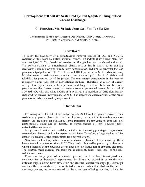
To verify the feasibility <strong>of</strong> a simultaneous removal process <strong>of</strong> SO 2 and NO X in<br />
combustion flue gases by pulsed streamer coronas, an industrial-scale pilot plant that<br />
can treat 1,800 Nm 3 /h <strong>of</strong> coal-fired combustion flue gas has been developed and tested.<br />
The system consists <strong>of</strong> a nonthermal plasma reactor that is similar to an existing<br />
electrostatic precipitator with wire-to-plate configuration, and a pulse generator that can<br />
generate output pulses <strong>of</strong> 130 kV, 500 ns, and 100 J per pulse. A MPC technique using<br />
Metglas magnetic switches was adopted to meet an acceptable level <strong>of</strong> lifetime and<br />
reliability for practical use <strong>of</strong> the process. The total energy consumption in this process<br />
is slightly higher than that <strong>of</strong> conventional methods. Therefore, as a part <strong>of</strong> energy<br />
saving, this paper deals with impedance matching conditions between the pulse<br />
generator and the plasma reactor, and reports some experimental results for removal <strong>of</strong><br />
SO 2 and NO X with and without C 2 H 4 as a additive. The addition <strong>of</strong> C 2 H 4 significantly<br />
enhanced the removal performance <strong>of</strong> NO X . The impedance characteristics <strong>of</strong> the pulse<br />
generator are also analyzed by experiments.<br />
I. Introduction<br />
The nitrogen oxides (NO X ) and sulfur dioxide (SO 2 ) in flue gases exhausted from<br />
coal-burning power plants, iron and steel plants, paper mills, internal-combustion<br />
engines are the major air pollutants. These pollutants are the cause <strong>of</strong> acid rain and<br />
photochemical smog and are harmful to human beings, so some countries have<br />
restricted their emissions.<br />
Many control devices are available, but due to increasingly stringent regulations,<br />
conventional devices tend to be expensive and huge. Therefore, a large market will be<br />
opened up because <strong>of</strong> the requirements for new regulations.<br />
Nonthermal - low temperature or nonequilibrium - plasma techniques among others<br />
have attracted our attention since 1970'. They can be obtained by producing a plasma in<br />
which a majority <strong>of</strong> the electrical energy goes into the production <strong>of</strong> energetic electrons.<br />
The electron mean energies are, therefore, considerably higher than those <strong>of</strong> the ions<br />
and the molecules.<br />
There are many types <strong>of</strong> nonthermal plasma that have been investigated and<br />
developed for environmental applications. But it can be created in essentially two<br />
different ways, electron-beam irradiation and electrical corona discharge [1]. Although<br />
work on the electron-beam process started a decade earlier than that on the corona<br />
discharge process, the corona method has the advantages <strong>of</strong> being modular, so it can be
used on a large or a small scale and can much more easily be retr<strong>of</strong>itted in existing<br />
power plants. In addition, it has a lower capital cost and no x-ray radiation shielding.<br />
Recently, it is recognized that the nonthermal plasma technique, especially a pulsed<br />
streamer corona method in applications <strong>of</strong> removal <strong>of</strong> SO 2 and NO X has several features<br />
such as being dry, good use <strong>of</strong> end products, simultaneous treatment, easy processing<br />
control, and no stack reheat. It is particularly efficient only when the pollutant is present<br />
in very small concentrations.<br />
Electrical corona discharge methods can be implemented in many ways, depending<br />
on the geometry <strong>of</strong> the plasma reactor and the electrical power supply (DC, AC, or<br />
pulsed). The types <strong>of</strong> electrical discharge reactors for the treatment <strong>of</strong> contaminated air<br />
include pulsed corona, ferroelectric bed, dielectric-barrier discharge, and surface<br />
discharge. Since pulsed corona reactors with a wire-to-plate configuration have shown<br />
very promising results and could be retr<strong>of</strong>itted to an existing electrostatic precipitator, it<br />
would be especially attractive.<br />
Generally, streamer corona discharge energized by a pulse voltage generator with a<br />
fast rise time can produce an intensive plasma, which effectively promotes gas-phase<br />
chemical reactions. Therefore, uniform streamer formation is necessary to achieve high<br />
performance in the streamer corona treatment. In the case <strong>of</strong> negative polarity, the<br />
ionization zone is limited to the vicinity <strong>of</strong> the discharge electrode and streamers do not<br />
propagate across the electrode spacing. However, positive streamers can propagate<br />
across the electrode spacing, ionizing the treatment volume to a larger degree and more<br />
uniformly [2]. Previous test results [3] show that the SO 2 removal efficiency is higher<br />
than that <strong>of</strong> negative corona when applied.<br />
Until now, both laboratory and pilot scale tests have been conducted in some<br />
countries [2~7]. Those results have indicated significant technical and economical<br />
advantages <strong>of</strong> the nonthermal plasma process based on the pulsed corona discharges<br />
compared to the electron beam process and other conventional methods. In 1988,<br />
industrial-scale experiments on the use <strong>of</strong> the pulsed streamer corona process for the<br />
simultaneous removal <strong>of</strong> NO X and SO 2 from combustion flue gas have been carried out<br />
by the Italian National Electricity Board (ENEL) at the coal-burning power station in<br />
Marghera, Italy [4]. According to the results, the energy consumption rate was up to 5<br />
% <strong>of</strong> electric power generated by the power plant. The energy consumption required by<br />
the process represents the largest operating cost and the transfer efficiency <strong>of</strong> the<br />
electrical energy from a wall-plug to the plasma in a reactor represents a key factor for<br />
the economical competitiveness <strong>of</strong> the process.<br />
It is indispensable to enhance the chemical reaction efficiency and to reduce the<br />
energy consumption since the total energy consumption in the process depends both on<br />
the chemical efficiency <strong>of</strong> the plasma and the energy conversion efficiency from the<br />
main power source to the corona streamers. From the viewpoint <strong>of</strong> energy saving, for<br />
example, the injection <strong>of</strong> chemical additives should be considered and the energy<br />
efficiency in a pulse generator also could be increased up to 80 %.<br />
II. Experimental Setup<br />
1. Pulsed streamer corona reactor
The corona reactor designed and manufactured in this work is very similar to an<br />
existing EP(Electrostatic Precipitator) with wire-to-plate geometry as shown in Fig. 1. It<br />
is comprised <strong>of</strong> two fields, each field contains four channels with a plate distance <strong>of</strong> 160<br />
mm, a length <strong>of</strong> 1.6 m, and a height <strong>of</strong> 1.5 m. The discharge part <strong>of</strong> the reactor consists<br />
<strong>of</strong> a rectangular frame with 9 wire in each diameter <strong>of</strong> 3 mm, which is placed vertically<br />
at the center line between the plates.<br />
The capacitance <strong>of</strong> the reactor in connection with the inherent geometry was<br />
estimated in the vicinity <strong>of</strong> 3 nF. With this value and a rise time <strong>of</strong> output pulse voltage<br />
generated from the pulse generator, the maximum permissible inductance in the<br />
discharge circuit can be calculated as follows [5]:<br />
2<br />
−9<br />
(3⋅<br />
tr ) (3×<br />
100 × 10 )<br />
L = =<br />
≈ 3µ<br />
H<br />
2<br />
2 −9<br />
π ⋅ C π × 3×<br />
10<br />
where, t r : the rise time <strong>of</strong> pulse voltage<br />
C : the capacitance <strong>of</strong> the reactor.<br />
2<br />
(1)<br />
Satisfying that value and reducing the stray inductance, it is necessary to construct a<br />
very compact reactor and to connect a generator to a reactor as short as possible. The<br />
latter means that a connection lead cable should be straight and short. Detailed<br />
characteristics <strong>of</strong> the reactor are summarized in table 1.<br />
Table 1. Main characteristics <strong>of</strong> the pulsed corona reactor.<br />
Gas flow rate<br />
1,800 Nm 3 /h, max.<br />
Emitting wire diameter<br />
3 mm, round type<br />
Distance between plates<br />
160 mm<br />
Distance between wires<br />
130 mm<br />
Number <strong>of</strong> channels 4<br />
Number <strong>of</strong> fields 2<br />
Total length <strong>of</strong> wires<br />
108 m<br />
1.6 m 1.6 m<br />
Flue gas<br />
in<br />
Emitting wire (positive)<br />
Plate (negative)<br />
Flue gas<br />
out<br />
Fig 1. HANJUNG pulsed streamer corona reactor.
2. High power pulse generator<br />
Taking account <strong>of</strong> the previous test results [4, 8], the optimal condition for a pulse<br />
generator requires that it should be able to generate a pulse voltage <strong>of</strong> 150 kV peak,<br />
pulse current up to 10 kA peak, a pulse width <strong>of</strong> 500 ns at FWHM (full width at half<br />
maximum), and approximately 800 J per pulse. It must, moreover, run continuously at<br />
pulse repetition rates between 100 pps (pulse per second) and 300 pps, and have at least<br />
a maintenance interval <strong>of</strong> 6 months as a baseline. The lifetime and reliability <strong>of</strong> the<br />
system are extremely important as downtime for maintenance affects plant availability,<br />
either scheduled or unscheduled.<br />
It is obvious that one <strong>of</strong> the key components for a pulse generator to meet those<br />
specifications is the switch system. Some <strong>of</strong> switches are available commercially for<br />
pulse power applications. However, a magnetic switch that has solid-state and nonlinear<br />
inductance characteristics is the only one to achieve completely the above specifications<br />
because other switches, in general, have poor lifetimes and higher cost levels [5,9].<br />
Based on Melville pulse compression networks [10], the MPC (Magnetic pulse<br />
compression) method using saturable reactors and pulse forming capacitors is a useful<br />
technique to make high power pulses having a narrow width and a steep rise front. The<br />
main features <strong>of</strong> the MPC type pulse generator are a long lifetime and high reliability<br />
because <strong>of</strong> its solid-state properties. These are very important to the industrial<br />
applications.<br />
Fig. 2 shows a simplified circuit <strong>of</strong> the pulse generator developed with a high voltage<br />
DC power supply (Maxwell model CCDS850P1480, 4 units paralleled), MPC switches<br />
(Metglas 2605CO), and a pulse transformer. The use <strong>of</strong> a pulse transformer and a<br />
constant current capacitor charging type HVDC power supply makes the generator<br />
simple, reliable, and efficient. Especially a DC power supply adopting the above type<br />
can eliminate much <strong>of</strong> the energy loss assessed in conventional resistive charging <strong>of</strong> an<br />
initial stage capacitor with a constant voltage power supply.<br />
The operation principle <strong>of</strong> Fig. 2 is as follows. First, the capacitor C 0 is charged by<br />
the HVDC power supply up to 50 kVmax. Charged energy in C 0 is transferred to C 1<br />
through L 0 , the charging inductor, by switching <strong>of</strong> SW 0 (thyratron, EEV model<br />
CX1525A) during 3 µs. After charging C 1 , MPC1 is saturated and the energy stored in<br />
C 1 is transferred to C2 through the pulse transformer. The output pulse from C 2 is<br />
compressed again by MPC2 (500 ns, F<br />
HV DC<br />
Charger<br />
50 kVmax<br />
32 kJ/s<br />
+<br />
R1<br />
50Ω<br />
D1<br />
R2<br />
50Ω<br />
C0<br />
160nF<br />
SW0<br />
L0<br />
11.4µH<br />
MPC 1<br />
C1<br />
160nF<br />
1:4<br />
MPC 2<br />
C2<br />
10nF<br />
To Osc.<br />
To Osc.<br />
Fig 2. Schematic circuit diagram <strong>of</strong> the MPC pulse generator.
Table 2. Design parameters <strong>of</strong> the MPC pulse generator.<br />
Maximum output power<br />
30 kW<br />
Peak output voltage<br />
100 ~ 130 kV<br />
Peak output current<br />
5 kA<br />
Pulse energy<br />
100 J<br />
Maximum repetition rate<br />
300 pps<br />
Pulse width (FWHM)<br />
500 ns<br />
Pulse rise time (10 ~ 90 %)<br />
100 ns<br />
Efficiency ~ 80 %<br />
Maintenance interval<br />
> 3 × 10 9 pulses<br />
WHM). In order to protect the HVDC power supply against voltage reversal, resistor R 1<br />
and R 2 and diode D 1 are inserted. The generator can deliver about 100 J per pulse with<br />
pulse repetition rate up to 300 pps to the plasma reactor. Table 2 summarizes the design<br />
parameters <strong>of</strong> the pulse generator.<br />
3. Pilot plant and measurement systems<br />
The layout <strong>of</strong> the pilot plant built in HANJUNG is shown in Fig. 3. These facilities<br />
have the gas cleaning capacity <strong>of</strong> 1,800 Nm 3 /h, equal to gas capacity <strong>of</strong> <strong>0.5</strong> MW, which<br />
is bypassed from the main stream <strong>of</strong> the pulverized coal combustion system with 2,500<br />
Nm 3 /h. This facility is composed <strong>of</strong> a bag filter to collect fly ashes from the flue gas, a<br />
heat exchanger to control temperature at the inlet <strong>of</strong> the reactor, the pulsed streamer<br />
corona reactor energized by the MPC pulse generator, an EP to collect ammonium salts<br />
produced by the process, and an induced draft fan.<br />
In this work, additional SO 2 and NO gases are injected into the flue gas at the<br />
downstream <strong>of</strong> the heat exchanger to simulate the real coal-fired combustion flue gas<br />
compositions, and then ammonia and a chemical additive, C 2 H 4 , are injected into the<br />
upstream <strong>of</strong> the reactor.<br />
The output pulse voltage and current are measured using a digital oscilloscope<br />
(Tektronix model TDS744A) having an analog bandwidth <strong>of</strong> 500 MHz and a sampling<br />
rate <strong>of</strong> 2 GS/s, a 4000:1 resistive voltage divider (Haefely Trench model 550483), and a<br />
wideband current transformer (Pearson model 4997). All the signal waveforms acquired<br />
by the oscilloscope are saved for analysis on such things as electrical diagnostics and<br />
energy estimations.<br />
Power input to the HVDC power supply was also monitored using a three-phase watthour<br />
meter so that a wall-plug efficiency <strong>of</strong> the reactor could be calculated. Gas analysis<br />
with regard to SO 2 and NO X (= NO + NO 2 ) was performed with a chemiluminescent<br />
NO X analyzer and a pulsed UV fluorescent SO 2 analyzer (both Thermo Environmental<br />
Co.). The temperature was measured at both inlet and outlet <strong>of</strong> the reactor.
6,000<br />
1,390<br />
7,000<br />
6<br />
1<br />
2<br />
8<br />
3 4<br />
5<br />
7<br />
Fig 3. Layout <strong>of</strong> the industrial scale pilot plant installed at HANJUNG. ➀ Coal<br />
combustor, ➁ Bag filter, ➂ Heat exchanger, ➃ Pulsed corona reactor, ➄ EP, ➅<br />
Sampling port for measurement, ➆ ID fan, ➇ Pulse generator.<br />
III. Results and Discussions<br />
1. Dummy load test<br />
The matching between the pulse generator and the reactor is a crucial point to reduce<br />
electrical energy loss and to optimize the formation <strong>of</strong> streamer coronas [2]. Therefore,<br />
the output impedance <strong>of</strong> the generator should match that <strong>of</strong> the reactor in order to obtain<br />
the maximum transfer <strong>of</strong> energy to a load.<br />
The generator was tested to find out the characteristics <strong>of</strong> its output impedance and a<br />
maximum transfer condition <strong>of</strong> output pulse energy to a load. Different non-inductive<br />
resistors (Carborundum Co.) were used as a load and pulse repetition rate was 1 pps.<br />
With 30 kV <strong>of</strong> HVDC output, the maximum energy transfer occurs at 35 o C, as<br />
shown in Fig. 4. The transferred energy and efficiency to the resistor per pulse were 49 J<br />
and 68 %, respectively. Transfer efficiency has the same trend as Fig. 4. The efficiency<br />
<strong>of</strong> the generator and the energy per pulse were calculated using<br />
EL<br />
η (%) = × 100<br />
(2)<br />
1 2<br />
C0<br />
⋅VDC<br />
2<br />
τ<br />
E L =<br />
∫V<br />
( t)<br />
I ( t)<br />
dt<br />
(3)<br />
0<br />
where, C 0 : the capacitance <strong>of</strong> the initial capacitor<br />
V DC : the output voltage <strong>of</strong> the HVDC supply<br />
and τ : the pulse duration.<br />
The power to a load is obtained by multiplying the energy per pulse dissipated in the
load by the pulse repetition rate. Fig. 5 shows the current and voltage waveforms versus<br />
time for 35 Ω. The pulse voltage has 70.32 kV pk , 280 ns rise time, and 640 ns duration.<br />
The current signal has 1.51 kA pk , 220 ns, and 630 ns.<br />
The impedance <strong>of</strong> discharge was computed with waveforms acquired by the<br />
oscilloscope as a function <strong>of</strong> time. All through the experiments, it is found that there is a<br />
constant impedance region and the value <strong>of</strong> impedance at the<br />
Energy / Pulse (J)<br />
60<br />
50<br />
40<br />
30<br />
20<br />
10<br />
0<br />
0 50 100 150 200<br />
Resistance (Ω)<br />
Voltage (kV)<br />
80<br />
70<br />
60<br />
50<br />
40<br />
30<br />
20<br />
1.6<br />
1.4<br />
1.2<br />
1<br />
0.8<br />
0.6<br />
0.4<br />
10<br />
0.2<br />
0<br />
0<br />
-10<br />
-0.2<br />
0 1 2 3 4 5<br />
Time (µs)<br />
Current (kA)<br />
Fig 4. The transferred energy into Fig 5. Voltage and current veforms<br />
the dummy loads. On the 35 W dummy load.<br />
Impedance (W)<br />
350<br />
300<br />
250<br />
200<br />
150<br />
100<br />
50<br />
70<br />
60<br />
50<br />
40<br />
30<br />
20<br />
10<br />
Energy efficiency (%)<br />
0<br />
55 60 65 70 75<br />
Voltage (kV)<br />
Fig 6. Impedance <strong>of</strong> the reactor (◆) and energy transfer efficiency (▲) as a<br />
function <strong>of</strong> the peak voltage applied.<br />
region implies the minimum resistance <strong>of</strong> discharge. The minimum resistance is always<br />
roughly equal to the value <strong>of</strong> peak voltage divided by the peak current.<br />
Fig. 6 shows a method to reduce impedance value <strong>of</strong> the reactor and to increase nergy<br />
efficiency. With increasing the peak voltage applied, impedance <strong>of</strong> the reactor decreases<br />
and energy efficiency also increases.<br />
0
2. Removal <strong>of</strong> SO 2<br />
Fig. 7 shows the removal <strong>of</strong> SO 2 as a function <strong>of</strong> the molar ratio <strong>of</strong> NH 3 to SO 2 in<br />
flue gas. In this test, peak values <strong>of</strong> applied voltage and current and pulse repetition rate<br />
were 43.6 kV, 0.35 kA, and 90 pps, respectively. A variation <strong>of</strong> consumption <strong>of</strong> the<br />
electrical energy was constant during SO 2 removal tests.<br />
Without injection <strong>of</strong> NH 3 , the removal rate was only about 8 %. In general, the<br />
efficiency <strong>of</strong> SO 2 removal by a gas phase radical reaction is known only to be about 10<br />
%. Although the removal process <strong>of</strong> SO 2 is mainly governed by the thermochemical<br />
reaction with ammonia and the heterogeneous chemical reaction, it can be enhanced by<br />
the pulsed streamer corona process [11]. When only NH 3 was injected into the gas with<br />
a 2:1 molar ratio to the initial SO 2 concentration, about 294 ppm <strong>of</strong> the initial 300 ppm<br />
SO 2 was removed. However, care must be taken with regards to secondary pollution<br />
production due to unreacted NH 3 . During this experiment, emissions <strong>of</strong> NH 3 were<br />
detected up to 26 ppm. In addition, there must have been an unreacted additive even<br />
though we did not measure it. One <strong>of</strong> the methods that can reduce the emission <strong>of</strong> NH 3<br />
as well as that <strong>of</strong> chemical additives is to modify the injection method or positions <strong>of</strong><br />
NH 3 or chemical additives such as using a corona radical shower method [12].<br />
100<br />
50<br />
SO2 Removal Rate (%)<br />
80<br />
60<br />
40<br />
20<br />
40<br />
30<br />
20<br />
10<br />
NH 3 Concentration (ppm)<br />
0<br />
0<br />
0 <strong>0.5</strong> 1 1.5 2 2.5<br />
Ratio (NH3/SO2)<br />
Fig 7. SO 2 removal rate(g) as a function <strong>of</strong> the molar ratio <strong>of</strong> NH 3 to SO 2 and<br />
emission <strong>of</strong> unreacted NH 3 (n) at outlet <strong>of</strong> the reactor. The gas<br />
consisted <strong>of</strong> 18 % O 2 and 38 ppm CO. The flow rate and temperature<br />
<strong>of</strong> the gas were 1,200 Nm 3 /h and 118 o C, respectively.<br />
3. Removal <strong>of</strong> NO X<br />
The tests were carried out to clarify the effect <strong>of</strong> the hydrocarbon additive, C 2 H 4 , and<br />
the energy input into the reactor on NO X removal efficiency. Fig. 8 shows the removal<br />
rates <strong>of</strong> NO, NO 2 , and NO X with and without the addition <strong>of</strong> C 2 H 4 in flue gas. The<br />
initial concentration <strong>of</strong> NO X was (a) 245 ppm and (b) 312 ppm, and the voltage pulses
having a peak value <strong>of</strong> 85 kV were applied to the reactor.<br />
As shown in Fig. 8 (a), in the case <strong>of</strong> no additive, the removal rate <strong>of</strong> NO increases<br />
with increasing the repetition rate <strong>of</strong> pulse but that <strong>of</strong> NO 2 decreases. This is because<br />
NO are oxidized to NO 2 by O and O 3 in plasma chemistry. Even though there is a<br />
difference between removal rates due to the higher or lower level <strong>of</strong> initial NO<br />
concentration, the removal characteristics <strong>of</strong> NO X are similar when no additives are<br />
injected.<br />
Fig. 8 (b) shows that the addition <strong>of</strong> C 2 H 4 greatly enhances the removal efficiency <strong>of</strong><br />
NO X up to 52 % with nearly the same energy input as Fig. 8 (a). This results from OH<br />
and HO 2 radicals, which can be produced by C 2 H 4 or hydrocarbon additives in the<br />
corona discharge process. NO and NO 2 are mainly converted into HNO 2 and HNO 3 by<br />
those radicals. The removal rates <strong>of</strong> NO, NO 2 , and NO X also increase as the pulse<br />
repetition rate increases.<br />
The above results indicate that the chemical additive could be very effective in<br />
reducing the energy cost for the removal <strong>of</strong> NO X using a nonthermal plasma technique.<br />
For the same energy input, higher NO X removal can be expected with higher additive<br />
concentrations. However, higher unreacted hydrocarbons will be produced at higher<br />
additive concentrations. It is, therefore, desirable to achieve NO X removal using the<br />
least amount <strong>of</strong> additive at an acceptable energy consumption.<br />
Fig. 9 shows the removal <strong>of</strong> NO X as a function <strong>of</strong> pulse repetition rates and peak<br />
voltage applied. The flow rate <strong>of</strong> the gas was 1,100 Nm 3 /h and the temperature at the<br />
inlet <strong>of</strong> the reactor was 120 o C. 600 ppm C 2 H 4 was added to the flue gas.<br />
Removal Rate (%)<br />
60<br />
40<br />
20<br />
0<br />
NO<br />
NO2<br />
NOx<br />
Removal Rate (%)<br />
80<br />
60<br />
40<br />
20<br />
NO<br />
NO2<br />
NOx<br />
-20<br />
0 50 100 150<br />
Pulse Repetition Rate (pps)<br />
(a) without C 2 H 4<br />
0<br />
0 50 100 150<br />
Pulse Repetition Rate (pps)<br />
(b) with C 2 H 4 (200 ppm)<br />
Fig 8. Effect <strong>of</strong> the additive and the input energy on NO X removal. The gas<br />
consisted <strong>of</strong> 13 % O 2 , 7 % CO 2 , and 20 ppm CO. The flow rate and<br />
temperature <strong>of</strong> the gas were 1,200 Nm 3 /h and 120 o C, respectively.<br />
By increasing the peak value <strong>of</strong> the pulse voltage from 60 kV to 90 kV, NO X removal<br />
rates were 44.8 % to 63.6 % at 90 pps and 71.2 % to 78.6 % at 200 pps. The removal<br />
rate <strong>of</strong> NO X increases with increasing the peak value <strong>of</strong> pulse voltage at lower pulse<br />
repetition rates but it has a saturation region. When a pulse repetition rate increases, the<br />
removal rates also increase but reaches a saturation point. Therefore, it is indispensable<br />
for consideration <strong>of</strong> economic aspects since the removal efficiency tends to saturate
owing to existence <strong>of</strong> the reverse reaction.<br />
100<br />
DeNOx Rate (%)<br />
80<br />
60<br />
40<br />
20<br />
60 kV<br />
80 kV<br />
90 kV<br />
0<br />
50 100 150 200 250<br />
Pulse Repetition Rate (pps)<br />
Fig 8. Effect <strong>of</strong> peak values and the input energy on NO x removal rate. The<br />
initial NO, NO2, and NOx concentration were 218, 70, and 288 ppm,<br />
respectively.<br />
About 79 % <strong>of</strong> the initial NO X concentration was removed with an energy<br />
consumption <strong>of</strong> 9.23 Wh/Nm 3 . At that time, the pulse repetition rate was 200 pps and<br />
the delivered energy to the reactor was 51 J, 90.32 kV <strong>of</strong> peak voltage and 1.55 kA <strong>of</strong><br />
peak current were measured. With reference to ENEL work [4], the NO X removal was<br />
50 % with initial NO X concentration <strong>of</strong> 240 ppm and about 12 Wh/Nm 3 <strong>of</strong> electrical<br />
energy was supplied to the gas.<br />
IV. Conclusions<br />
We have developed and tested an industrial-scale nonthermal plasma DeSO 2 and<br />
DeNO X pilot plant composed <strong>of</strong> a wire-to-plate type reactor and a MPC type pulse<br />
generator.<br />
As a part <strong>of</strong> energy saving, this paper reported the impedance characteristic and<br />
matching conditions between the pulse generator and the reactor, and showed some test<br />
results for the removal <strong>of</strong> SO 2 and NO X with and without a hydrocarbon additive.<br />
The results <strong>of</strong> the dummy load tests indicated that the output impedance <strong>of</strong> the pulse<br />
generator was about 35 Ω. Matching between a reactor and a pulse generator, the<br />
impedance <strong>of</strong> the reactor should be equal to that <strong>of</strong> the pulse generator when voltage<br />
pulses are applied to the reactor, if possible.<br />
The experimental results obtained at 118 o C show that removal efficiency <strong>of</strong> SO 2 with<br />
a molar ratio <strong>of</strong> 2:1 is 98 % when compared to that <strong>of</strong> SO 2 <strong>of</strong> 8 % without NH 3 . The<br />
addition <strong>of</strong> C 2 H 4 significantly enhanced the performance <strong>of</strong> NO X removal with up to 79<br />
% with an energy consumption <strong>of</strong> 9.23 Wh/Nm 3 . But the removal efficiency <strong>of</strong> NO X<br />
does not increase monotonically.
In conclusion, the present simultaneous DeSO X -DeNO X system using a nonthermal<br />
plasma method is found to be competitive with existing technologies.<br />
Further research is needed, especially focusing on optimization to improve removal<br />
efficiency, to modify injection methods <strong>of</strong> an additive, and to reduce energy<br />
requirements. For example, the effect <strong>of</strong> gas residence time and geometry <strong>of</strong> a reactor<br />
on removal <strong>of</strong> NO X and SO 2 should be investigated. Furthermore, the efficiency <strong>of</strong> a<br />
pulse generator should be higher and the size <strong>of</strong> the pulse generator should also be<br />
smaller.<br />
References<br />
1. B. M. Penetrante and S. E. Schultheis, Eds., Non-Thermal Plasma Techniques for<br />
Pollution Control, NATO ASI Series G, vol. 34, part A, B. Berlin Heidelberg:<br />
Springer-Verlag, 1993.<br />
2. M. Rea and K. Yan, Energization <strong>of</strong> pulse corona induced chemical processes, Non-<br />
Thermal Plasma Techniques for Pollution Control, NATO ASI Series G, vol. 34,<br />
part A. Berlin Heidelberg: Springer-Verlag, pp. 191-204, 1993.<br />
3. A. Mizuno, J. S. Clements, and R. H. Davis, "A method for the removal <strong>of</strong> sulfur<br />
dioxide from exhaust gas utilizing pulsed streamer corona for electron energization,"<br />
IEEE Trans. Ind. Appl., vol. IA-22, no. 3, May/June pp. 516-521, 1986.<br />
4. G. Dinelli, L. Civitano, and M. Rea, "Industrial experiments on pulse corona<br />
simultaneous removal <strong>of</strong> NO X and SO 2 from flue gas," IEEE Trans. Ind. Appl., vol.<br />
26, no. 3, May/June, pp. 535-541, 1990.<br />
5. J. M. Rasmussen, "High power short duration pulse generator for SO X and NO X<br />
removal," Conf. Rec. IEEE IAS Annul. Meeting, pp. 2180-2184, 1989.<br />
6. T. Fujii, R. Gobbo, and M. Rea, "Pulse corona characteristics," IEEE Trans. Ind.<br />
Appl., vol. 29, no. 1, Jan./Feb., pp. 98-101, 1993.<br />
7. W. Yan, W. Ninghui, Z. Yimin, and Z. Yanbin, "SO 2 removal from industrial flue<br />
gases using pulsed corona discharge," J. Electrostatics, vol. 44, pp. 11-16, 1998.<br />
8. S. Ashby, D. Bhasavanich, C. Deeney, L. Schlitt, and L. Civitano, "Modulator<br />
options for pulsed corona discharge pollution control," Proc. 9th IEEE Pulsed<br />
Power Conf., Albuquerque, NM, pp. 445-447, 1993.<br />
9. J. S. Oh, S. S. Park, S. D. Jang, M. H. Cho, I. S. Ko, and W. Namkung, "Prototype<br />
2-stage magnetic pulse compression modulator for pulse power application," Conf.<br />
Rec. 1996 22nd Int'l Power Modulator Symposium, Boca Raton, Florida, June, pp.<br />
186-189, 1996.<br />
10. W. S. Melville, "The use <strong>of</strong> saturable reactors as discharge for pulse generators,"<br />
Proc. IEE, vol. 98, part 3, pp. 185-207, 1951.<br />
11. L. Civitano, Industrial application <strong>of</strong> pulsed corona processing to flue gas, Non-<br />
Thermal Plasma Techniques for Pollution Control, NATO ASI Series G, vol. 34,<br />
part B. Berlin Heidelberg: Springer-Verlag, pp. 103-130, 1993.<br />
12. J. S. Chang, P. C. Looy, K. Nagai, T. Toshioka, S. Aoki, and A. Maezawa,<br />
"Preliminary pilot plant tests <strong>of</strong> a corona discharge-electron beam hybrid<br />
combustion flue gas cleaning system," IEEE Trans. Ind. Appl., vol. 32, no. 1,<br />
Jan./Feb., pp. 131-137, 1996.