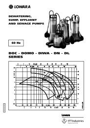
CEA-CA SERIES
CEA-CA SERIES
CEA-CA SERIES

Create successful ePaper yourself
Turn your PDF publications into a flip-book with our unique Google optimized e-Paper software.
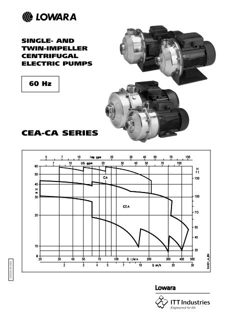
SINGLE- AND<br />
TWIN-IMPELLER<br />
CENTRIFUGAL<br />
ELECTRIC PUMPS<br />
60 Hz<br />
<strong>CEA</strong>-<strong>CA</strong> <strong>SERIES</strong><br />
EDITION 09-2003
Single-<br />
Impeller<br />
Centrifugal<br />
Electric<br />
Pumps<br />
<strong>CEA</strong>M-<strong>CEA</strong><br />
Series<br />
MARKET SECTORS<br />
CIVIL, AGRICULTURAL, INDUSTRIAL.<br />
APPLI<strong>CA</strong>TIONS<br />
• Handling of chemically and mechanically nonaggressive<br />
water and liquids (*).<br />
• Water supply.<br />
• Irrigation.<br />
• Water circulation (cold, hot, refrigerated).<br />
*<br />
For moderately aggressive liquids, a version with FPM elastomers is available (<strong>CEA</strong>.../...-V). For very aggressive liquids, please contact<br />
our sales network.<br />
- Three-phase version:<br />
220-230/380-400 V 60 Hz, 2<br />
poles, the overload protection<br />
must be provided and installed by<br />
the user in the control panel.<br />
• Condensate drain plugs in the<br />
standard version.<br />
SPECIFI<strong>CA</strong>TIONS<br />
PUMP<br />
• Delivery up to 460 l/min<br />
(28 m 3 /h).<br />
Head up to 45 m.<br />
• Temperature of pumped liquid: -<br />
10°C to 85°C standard version (**).<br />
• Maximum operating pressure: 8<br />
bar (PN 8).<br />
• Counterclockwise rotation facing the<br />
pump from the suction port.<br />
** 110°C <strong>CEA</strong>.../...-V versions<br />
MOTOR<br />
• Asynchronous, squirrel cage rotor,<br />
closed construction, external<br />
ventilation.<br />
Protection class: IP55.<br />
Insulation: class F.<br />
• Performances to EN 60034-1<br />
specifications.<br />
• Standard voltage:<br />
- Single-phase versions:<br />
220-230V 60 Hz, 2 poles, with<br />
automatic reset overload protection<br />
up to 1.5 kW. For higher powers,<br />
the overload protection must be<br />
provided and installed by the user<br />
in the control panel.<br />
CONSTRUCTION<br />
CHARACTERISTICS<br />
• Close-coupled, single-impeller<br />
centrifugal pump featuring axial<br />
suction and radial discharge.<br />
• Compact construction, with pump<br />
coupled directly to motor; special<br />
motor shaft extension supported by<br />
ball bearings.<br />
• Rotating assembly has back pull-out<br />
design, no need to disconnect the<br />
pump body from the pipe line.<br />
• Threaded suction and discharge<br />
ports (Rp UNI-ISO 7)<br />
• High performance closed<br />
impeller made of AISI 304<br />
stainless steel.<br />
• Mechanical seal with<br />
ceramic/carbon rings, NBR<br />
elastomers, other parts are made of<br />
AISI 304 stainless steel. Mounting<br />
dimensions according to EN 12756<br />
(ex DIN 24960) and ISO 3069.<br />
NBR O-rings.<br />
• Mounting pedestal.<br />
OPTIONAL<br />
FEATURES<br />
Different voltages and frequencies.<br />
• Different materials for the<br />
mechanical seal and O-rings.<br />
3
MATERIALS<br />
PART<br />
MATERIALS<br />
UNI ASTM - AISI EN - DIN<br />
Pump body Stainless steel X5 CrNi 18-10 304 1.4301<br />
Seal housing Stainless steel X5 CrNi 18-10 304 1.4301<br />
Diffuser Stainless steel X5 CrNi 18-10 304 1.4301<br />
Impeller Stainless steel X5 CrNi 18-10 304 1.4301<br />
Shaft extension Stainless steel X5 CrNiMo 17-12-2 316 1.4401<br />
Impeller fastening nut Stainless steel X5 CrNiMo 17-12-2 316 1.4401<br />
Fill/drain plugs Stainless steel X5 CrNiMo 17-12-2 316 1.4401<br />
Seals for fill/drain plugs<br />
NBR (FPM in the <strong>CEA</strong>-V versions)<br />
Mechanical seal<br />
Ceramic/Carbon/NBR (Ceramic/Carbon/FPM in the <strong>CEA</strong>-V versions)<br />
O-rings<br />
NBR (FPM in the <strong>CEA</strong>-V versions)<br />
Adapter<br />
Aluminium<br />
Mounting pedestal<br />
Enamelled steel<br />
Pump body nuts and bolts<br />
Zinc-plated steel<br />
<strong>CEA</strong> MECHANI<strong>CA</strong>L SEAL<br />
The standard configuration has the characteristics<br />
shown in fig. 1 and table 1.<br />
STANDARD MATERIALS (TABLE 1)<br />
POS. COMPONENT MATERIAL<br />
1 Spring AISI 304 stainless steel<br />
2 Shaft seal NBR<br />
3 Armature AISI 304 stainless steel<br />
4 Rotating assembly seal NBR<br />
5 Rotating assembly seal ring Ceramic<br />
6 Fixed assembly ring Carbon<br />
7 Fixed assembly seal NBR<br />
Different materials are available on request.<br />
The special configuration has the characteristics shown in fig. 1<br />
and table 2.<br />
A version with fixed assembly anti-rotation lockpin is available on<br />
request.<br />
ALTERNATIVE MATERIALS (TABLE 2)<br />
(ON REQUEST)<br />
POS.<br />
1-2-3-4-7 5 - 6<br />
MATERIAL<br />
Ceramic - Carbon<br />
Ceramic - Special carbon<br />
EPDM Silicon carbide - Special carbon<br />
Silicon carbide - Tungsten carbide<br />
Tungsten carbide - Tungsten carbide*<br />
Ceramic - Carbon<br />
Ceramic - Special carbon<br />
FPM Silicon carbide - Special carbon<br />
AISI 316 Silicon carbide - Silicon carbide<br />
Silicon carbide - Tungsten carbide<br />
Tungsten carbide - Tungsten carbide*<br />
* A version with anti-rotation lockpin is available.<br />
(FIG. 1)<br />
4
HYDRAULIC PERFORMANCE TABLE, <strong>CEA</strong>-<strong>CEA</strong>M <strong>SERIES</strong> 60 Hz<br />
PUMP TYPE RATED<br />
Q = DELIVERY<br />
POWER l/min 0 20 30 40 60 80 120 140 160 180 240 300 315 325 360 400 440 460<br />
m 3 /h 0 1,2 1,8 2,4 3,6 4,8 7,2 8,4 9,6 10,8 14,4 18 18,9 19,5 21,6 24 26 28<br />
kW HP<br />
H = TOTAL HEAD METERS COLUMN OF WATER<br />
<strong>CEA</strong>(M) 706/3 0,75 1 32,3 30,7 30,0 29,2 27,0 23,5<br />
<strong>CEA</strong>(M) 706/4 0,9 1,2 39,2 37,5 36,6 35,7 33,4 28,7<br />
<strong>CEA</strong>(M) 706/5 1,1 1,5 45,2 43,3 42,4 41,4 38,6 31,6<br />
<strong>CEA</strong>(M) 1206/1 0,55 0,75 22,1 19,1 17,7 14,4 12,2 9,8<br />
<strong>CEA</strong>(M) 1206/2 0,75 1 27,8 24,1 22,6 19,1 16,9 14,3<br />
<strong>CEA</strong>(M) 1206/3 0,9 1,2 32,8 29,1 27,7 24,1 22,0 19,6<br />
<strong>CEA</strong>(M) 1206/4 1,5 2 40,5 36,3 34,6 30,6 28,2 25,4<br />
<strong>CEA</strong>(M) 1206/5 1,85 2,5 46,6 42,2 40,4 36,0 33,4 30,6 27,4<br />
<strong>CEA</strong>(M) 2106/0 0,75 1 17,0 15,9 15,5 14,9 14,3 11,9 8,8<br />
<strong>CEA</strong>(M) 2106/1 1,1 1,5 21,1 20,4 20,0 19,5 19,0 16,9 14,0<br />
<strong>CEA</strong>(M) 2106/2 1,5 2 25,3 24,5 24,1 23,7 23,2 21,3 18,7 18,0<br />
<strong>CEA</strong>(M) 2106/3 1,85 2,5 30,0 29,4 29,1 28,8 28,3 26,7 24,3 23,5<br />
<strong>CEA</strong>(M) 2106/4 2,2 3 34,8 34,3 34,0 33,6 33,2 31,5 28,9 28,2 27,6<br />
<strong>CEA</strong>(M) 3706/0 1,1 1,5 16,9 15,9 15,6 14,4 12,8 12,4 12,0 10,8 9,1<br />
<strong>CEA</strong>(M) 3706/0A 1,5 2 19,8 19,4 19,2 18,4 17,2 16,8 16,5 15,4 13,8 11,9<br />
<strong>CEA</strong>(M) 3706/1 1,85 2,5 23,5 22,9 22,6 21,7 20,3 19,9 19,6 18,5 17,1 15,4 14,5<br />
cea-2p60-en_b_th<br />
PUMP TYPE INPUT INPUT <strong>CA</strong>PACITOR PUMP TYPE INPUT INPUT INPUT<br />
POWER* CURRENT* POWER* CURRENT* CURRENT*<br />
SINGLE-PHASE 220-230 V THREE-PHASE 220-230 V 380-400 V<br />
kW A µF / 450 V kW A A<br />
<strong>CEA</strong>M 706/3 0,96 4,39 20 <strong>CEA</strong> 706/3 0,89 2,93 1,69<br />
<strong>CEA</strong>M 706/4 1,30 5,91 25 <strong>CEA</strong> 706/4 1,15 3,65 2,11<br />
<strong>CEA</strong>M 706/5 1,54 7,13 30 <strong>CEA</strong> 706/5 1,40 4,17 2,41<br />
<strong>CEA</strong>M 1206/1 0,84 3,87 16 <strong>CEA</strong> 1206/1 0,74 2,36 1,36<br />
<strong>CEA</strong>M 1206/2 1,05 4,79 20 <strong>CEA</strong> 1206/2 0,99 3,14 1,81<br />
<strong>CEA</strong>M 1206/3 1,39 6,31 25 <strong>CEA</strong> 1206/3 1,24 3,88 2,24<br />
<strong>CEA</strong>M 1206/4 1,85 8,71 40 <strong>CEA</strong> 1206/4 1,70 5,09 2,94<br />
<strong>CEA</strong>M 1206/5 2,23 10,6 40 <strong>CEA</strong> 1206/5 2,05 6,26 3,62<br />
<strong>CEA</strong>M 2106/0 1,06 4,85 20 <strong>CEA</strong> 2106/0 1,00 3,17 1,83<br />
<strong>CEA</strong>M 2106/1 1,50 6,98 30 <strong>CEA</strong> 2106/1 1,37 4,09 2,36<br />
<strong>CEA</strong>M 2106/2 1,90 8,87 40 <strong>CEA</strong> 2106/2 1,75 5,21 3,01<br />
<strong>CEA</strong>M 2106/3 2,29 10,8 40 <strong>CEA</strong> 2106/3 2,12 6,43 3,71<br />
<strong>CEA</strong>M 2106/4 3,02 14,2 40 <strong>CEA</strong> 2106/4 2,86 8,35 4,82<br />
<strong>CEA</strong>M 3706/0 1,54 7,15 30 <strong>CEA</strong> 3706/0 1,41 4,19 2,42<br />
<strong>CEA</strong>M 3706/0A 1,97 9,19 40 <strong>CEA</strong> 3706/0A 1,84 5,44 3,14<br />
<strong>CEA</strong>M 3706/1 2,51 11,7 40 <strong>CEA</strong> 3706/1 2,35 7,00 4,04<br />
* Maximum value in specified range cea-2p60-en_b_te<br />
IDENTIFI<strong>CA</strong>TION CODE<br />
The <strong>CEA</strong>M-<strong>CEA</strong> models are identified as shown in the following table.<br />
C E A M 1 2 0 6 / 5 – V<br />
FPM version<br />
Impeller size<br />
60 Hz<br />
Flow rate in l/min.<br />
Single-phase version<br />
Series<br />
5
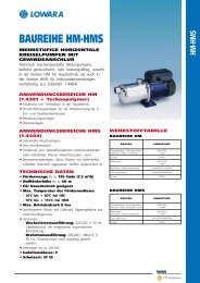
HYDRAULIC PERFORMANCE RANGE, <strong>CEA</strong> <strong>SERIES</strong> 60 HZ,<br />
2 POLES (3450 rpm)<br />
6
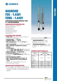
<strong>CEA</strong>706 <strong>SERIES</strong><br />
OPERATING CHARACTERISTICS AT 3450 rpm, 60 Hz<br />
These performances are valid for liquids with density = 1.0 Kg/dm 3 and kinematic viscosity = 1 mm 2 /sec.<br />
7
<strong>CEA</strong>1206 <strong>SERIES</strong><br />
OPERATING CHARACTERISTICS AT 3450 rpm, 60 Hz<br />
These performances are valid for liquids with density = 1.0 Kg/dm 3 and kinematic viscosity = 1 mm 2 /sec.<br />
8
<strong>CEA</strong>2106 <strong>SERIES</strong><br />
OPERATING CHARACTERISTICS AT 3450 rpm, 60 Hz<br />
These performances are valid for liquids with density = 1.0 Kg/dm 3 and kinematic viscosity = 1 mm 2 /sec.<br />
9
<strong>CEA</strong>3706 <strong>SERIES</strong><br />
OPERATING CHARACTERISTICS AT 3450 rpm, 60 Hz<br />
These performances are valid for liquids with density = 1.0 Kg/dm 3 and kinematic viscosity = 1 mm 2 /sec.<br />
10
DIMENSIONS AND WEIGHTS, <strong>CEA</strong> <strong>SERIES</strong>, 60 Hz<br />
PUMP TYPE DIMENSIONS (mm)<br />
DNA DNM WEIGHT<br />
A D H H1 H2 L L1 W kg<br />
<strong>CEA</strong>M 706/3 51 140 220 111 230 325 76 65 Rp 1¼ Rp 1 12,8<br />
<strong>CEA</strong>M 706/4 51 140 220 111 239 325 31 65 Rp 1¼ Rp 1 13<br />
<strong>CEA</strong>M 706/5 51 156 220 111 246 371 69 65 Rp 1¼ Rp 1 14,5<br />
<strong>CEA</strong>M 1206/1 51 140 220 111 230 325 76 65 Rp 1¼ Rp 1 11,7<br />
<strong>CEA</strong>M 1206/2 51 140 220 111 230 325 76 65 Rp 1¼ Rp 1 11,7<br />
<strong>CEA</strong>M 1206/3 51 140 220 111 239 325 31 65 Rp 1¼ Rp 1 11,7<br />
<strong>CEA</strong>M 1206/4 51 156 220 111 246 371 69 65 Rp 1¼ Rp 1 16,7<br />
<strong>CEA</strong>M 1206/5 51 176 220 111 230 402 114 65 Rp 1¼ Rp 1 21,5<br />
<strong>CEA</strong>M 2106/0 54 140 222 113 230 339 76 76 Rp 1½ Rp 1¼ 12,8<br />
<strong>CEA</strong>M 2106/1 54 156 222 113 246 385 69 76 Rp 1½ Rp 1¼ 16,8<br />
<strong>CEA</strong>M 2106/2 54 156 222 113 246 385 69 76 Rp 1½ Rp 1¼ 17<br />
<strong>CEA</strong>M 2106/3 54 176 222 113 230 416 114 76 Rp 1½ Rp 1¼ 21,6<br />
<strong>CEA</strong>M 2106/4 54 176 222 113 230 416 114 76 Rp 1½ Rp 1¼ 22<br />
<strong>CEA</strong>M 3706/0 54 156 222 113 246 385 69 76 Rp 2 Rp 1¼ 15<br />
<strong>CEA</strong>M 3706/0A 54 156 222 113 246 385 69 76 Rp 2 Rp 1¼ 21<br />
<strong>CEA</strong>M 3706/1 54 176 222 113 230 416 114 76 Rp 2 Rp 1¼ 15<br />
<strong>CEA</strong> 706/3 51 140 220 111 230 325 76 65 Rp 1¼ Rp 1 11<br />
<strong>CEA</strong> 706/4 51 140 220 111 230 325 76 65 Rp 1¼ Rp 1 12,7<br />
<strong>CEA</strong> 706/5 51 156 220 111 238 371 114 65 Rp 1¼ Rp 1 14,5<br />
<strong>CEA</strong> 1206/1 51 140 220 111 230 325 76 65 Rp 1¼ Rp 1 11,5<br />
<strong>CEA</strong> 1206/2 51 140 220 111 230 325 76 65 Rp 1¼ Rp 1 12,3<br />
<strong>CEA</strong> 1206/3 51 140 220 111 230 325 76 65 Rp 1¼ Rp 1 13<br />
<strong>CEA</strong> 1206/4 51 156 220 111 238 371 114 65 Rp 1¼ Rp 1 14,5<br />
<strong>CEA</strong> 1206/5 51 156 220 111 238 371 114 65 Rp 1¼ Rp 1 15<br />
<strong>CEA</strong> 2106/0 54 140 222 113 230 339 76 76 Rp 1½ Rp 1¼ 12,1<br />
<strong>CEA</strong> 2106/1 54 156 222 113 238 385 114 76 Rp 1½ Rp 1¼ 14<br />
<strong>CEA</strong> 2106/2 54 156 222 113 238 385 114 76 Rp 1½ Rp 1¼ 16<br />
<strong>CEA</strong> 2106/3 54 156 222 113 238 385 114 76 Rp 1½ Rp 1¼ 16,5<br />
<strong>CEA</strong> 2106/4 54 156 222 113 238 385 114 76 Rp 1½ Rp 1¼ 17<br />
<strong>CEA</strong> 3706/0 54 156 222 113 238 285 114 76 Rp 2 Rp 1¼ 14<br />
<strong>CEA</strong> 3706/0A 54 156 222 113 238 385 114 76 Rp 2 Rp 1¼ 16<br />
<strong>CEA</strong> 3706/1 54 156 222 113 238 385 114 76 Rp 2 Rp 1¼ 17<br />
cea-2p60-en_b_td<br />
11
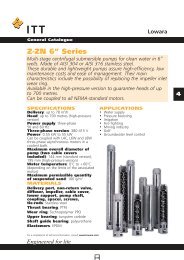
PUMP SECTION AND LIST OF MAIN COMPONENTS<br />
REF. N.<br />
DESCRIPTION<br />
1 Pump body<br />
2 Impeller<br />
3 Diffuser<br />
4 Seal housing<br />
5 Adapter<br />
7 Motor<br />
*12 Mechanical seal<br />
*13 O-ring<br />
*14 O-ring<br />
*15 O-ring<br />
16 Fill/drain plug<br />
26 Impeller fastening nut and washer<br />
27 Mounting pedestal<br />
* Recommended spare parts<br />
12
Twin-<br />
Impeller<br />
Centrifugal<br />
Electric<br />
Pumps<br />
<strong>CA</strong>M-<strong>CA</strong><br />
Series<br />
MARKET SECTORS<br />
CIVIL, AGRICULTURAL, INDUSTRIAL.<br />
APPLI<strong>CA</strong>TIONS<br />
• Handling of chemically and mechanically nonaggressive<br />
water and liquids (*).<br />
• Water supply.<br />
• Irrigation.<br />
• Water circulation (cold, hot, refrigerated).<br />
*<br />
For moderately aggressive liquids, a version with FPM elastomers is available (<strong>CA</strong>.../...-V). For very aggressive liquids, please contact our<br />
sales network.<br />
protection must be provided and<br />
installed by the user in the control<br />
panel.<br />
- Three-phase version:<br />
220-230/380-400 V 60 Hz, 2<br />
poles, the overload protection<br />
must be provided and installed by<br />
the user in the control panel.<br />
• Condensate drain plugs in the<br />
standard version.<br />
SPECIFI<strong>CA</strong>TIONS<br />
PUMP<br />
• Delivery up to 210 l/min (12.5<br />
m 3 /h).<br />
Head up to 64 m.<br />
• Temperature of pumped liquid:<br />
-10°C to 85°C standard version (**).<br />
• Maximum operating pressure: 8<br />
bar (PN 8).<br />
• Counterclockwise rotation facing the<br />
pump from the suction port.<br />
** 110°C <strong>CA</strong>.../...-V versions<br />
MOTOR<br />
•<br />
Asynchronous, squirrel cage rotor,<br />
closed construction, external<br />
ventilation.<br />
Protection class: IP55.<br />
Insulation: class F.<br />
•<br />
specifications.<br />
•<br />
Performances to EN 60034-1<br />
Standard voltage:<br />
- Single-phase versions:<br />
220-230 V 60 Hz, 2 poles, with<br />
automatic reset overload<br />
protection up to 1.5 kW. For<br />
higher powers, the overload<br />
CONSTRUCTION<br />
CHARACTERISTICS<br />
• Close-coupled, single-impeller<br />
centrifugal pump featuring axial<br />
suction and radial discharge.<br />
• Compact construction, with pump<br />
coupled directly to motor; special<br />
motor shaft extension supported by<br />
ball bearings.<br />
• Threaded suction and discharge<br />
ports (Rp UNI-ISO 7)<br />
• High performance closed<br />
impeller made of AISI 304<br />
stainless steel, keyed to motor shaft<br />
extension and held in place with<br />
tab and nut.<br />
• Mechanical seal with<br />
ceramic/carbon rings, NBR<br />
elastomers, other parts are made of<br />
AISI 304 stainless steel. Mounting<br />
dimensions according to EN 12756<br />
(ex DIN 24960) and ISO 3069.<br />
NBR O-rings.<br />
• Mounting pedestal.<br />
OPTIONAL<br />
FEATURES<br />
Different voltages and frequencies.<br />
• Different materials for the<br />
mechanical seal and O-rings.<br />
13
MATERIALS<br />
PART<br />
MATERIAL<br />
Pump body with seal housing Stainless steel X5 CrNi 18-10 304 1.4301<br />
Suction flange Stainless steel X5 CrNi 18-10 304 1.4301<br />
Diffuser Stainless steel X5 CrNi 18-10 304 1.4301<br />
Diffuser cover Stainless steel X5 CrNi 18-10 304 1.4301<br />
Final diffuser Stainless steel X5 CrNi 18-10 304 1.4301<br />
Final diffuser cover Stainless steel X5 CrNi 18-10 304 1.4301<br />
Impellers Stainless steel X5 CrNi 18-10 304 1.4301<br />
Impeller spacer Stainless steel X5 CrNi 18-10 304 1.4301<br />
Shaft extension Stainless steel X5 CrNi 18-10 304 1.4301<br />
Impeller fastening nut and washer Stainless steel X5 CrNi 18-10 304 1.4301<br />
Tab Stainless steel X5 CrNiMo 17-12-2 316 1.4401<br />
Fill/drain plugs Stainless steel X5 CrNiMo 17-12-2 316 1.4401<br />
Seals for fill/drain plugs<br />
NBR (FPM in the <strong>CEA</strong>-V versions)<br />
Mechanical seal<br />
Ceramic/Carbon/NBR (Ceramic/Carbon/FPM in the <strong>CA</strong>-V versions)<br />
Impeller shoulder washer Stainless steel X5 CrNi 18-10 304 1.4301<br />
O-rings<br />
NBR (FPM in the <strong>CA</strong>-V versions)<br />
Adapter<br />
Aluminium<br />
Mounting pedestal<br />
Aluminium<br />
Pump body nuts and bolts<br />
Treated steel<br />
<strong>CA</strong> MECHANI<strong>CA</strong>L SEAL<br />
The standard configuration has the characteristics shown in fig. 1<br />
and table 1.<br />
STANDARD MATERIALS (TABLE 1)<br />
UNI ASTM - AISI EN - DIN<br />
POS. COMPONENT MATERIAL<br />
1 Spring AISI 316 stainless steel<br />
2 Shaft seal NBR<br />
3 Armature AISI 304 stainless steel<br />
4 Rotating assembly seal NBR<br />
5 Rotating assembly seal ring Ceramic<br />
6 Fixed assembly ring Carbon<br />
7 Fixed assembly seal NBR<br />
Different materials are available on request.<br />
The special configuration has the characteristics shown in fig. 1<br />
and table 2.<br />
A version with fixed assembly anti-rotation lockpin is available on<br />
request.<br />
ALTERNATIVE MATERIALS (TABLE 2)<br />
(ON REQUEST)<br />
POS.<br />
1-2-3-4-7 5 - 6<br />
MATERIAL<br />
Ceramic - Carbon<br />
Silicon carbide - Silicon carbide<br />
FPM<br />
Silicon carbide - Special carbon<br />
AISI 316<br />
Silicon carbide - Tungsten carbide<br />
AISI 304 Tungsten carbide - Special carbon<br />
Tungsten carbide - Tungsten carbide<br />
Ceramic - Carbon<br />
Ceramic - Special carbon<br />
EPDM<br />
Silicon carbide - Silicon carbide<br />
AISI 316<br />
Silicon carbide - Tungsten carbide<br />
AISI 304 Tungsten carbide - Special carbon<br />
Tungsten carbide - Tungsten carbide<br />
* A version with anti-rotation lockpin is available.<br />
(FIG. 1)<br />
14
HYDRAULIC PERFORMANCE TABLE, <strong>CA</strong>-<strong>CA</strong>M <strong>SERIES</strong> 60 Hz<br />
PUMP TYPE<br />
kW<br />
RATED<br />
POWER<br />
HP<br />
Q = DELIVERY<br />
l/min 0 30 40 50 60 70 80 90 120 150 180 210<br />
m 3 /h 0 1,8 2,4 3 3,6 4,2 4,8 5,4 7,2 9 10,8 12,6<br />
H = TOTAL HEAD METERS COLUMN OF WATER<br />
<strong>CA</strong>(M) 706/33 1,5 2 62,6 58,5 56,3 53,7 50,6 46,9 42,8 38,1<br />
<strong>CA</strong>(M) 1206/33 1,85 2,5 64,2 58,5 56,9 55,3 53,5 51,7 45,5 38,7<br />
<strong>CA</strong> 2006/33 3 4 62,4 59 58,2 55,2 51,7 47,6 43,2<br />
ca-2p60-en_b_th<br />
PUMP TYPE INPUT INPUT <strong>CA</strong>PACITOR PUMP TYPE INPUT INPUT INPUT<br />
POWER* CURRENT* POWER* CURRENT* CURRENT*<br />
SINGLE-PHASE 220-230 V THREE-PHASE 220-230 V 380-400 V<br />
kW A µF / 450 V kW A A<br />
<strong>CA</strong>M 706/33 2,01 9,32 40 <strong>CA</strong> 706/33 1,87 5,54 3,20<br />
<strong>CA</strong>M 1206/33 2,69 12,6 40 <strong>CA</strong> 1206/33 2,53 7,48 4,32<br />
- - - - <strong>CA</strong> 2006/33 3,54 10,3 5,97<br />
* Maximum value in specified range ca-2p60-en_b_te<br />
IDENTIFI<strong>CA</strong>TION CODE<br />
The <strong>CA</strong>M-<strong>CA</strong> models are identified as shown in the following table.<br />
C A M 1 2 0 6 / 5 5 – V<br />
FPM version<br />
Impeller size<br />
60 Hz<br />
Flow rate in l/min.<br />
Single-phase version<br />
Series<br />
15
HYDRAULIC PERFORMANCE RANGE, <strong>CEA</strong> <strong>SERIES</strong>, 60 Hz,<br />
2 POLES (3450 rpm)<br />
16
<strong>CA</strong>706 <strong>SERIES</strong><br />
OPERATING CHARACTERISTICS AT 3450 rpm 60 Hz<br />
These performances are valid for liquids with density = 1.0 Kg/dm 3 and kinematic viscosity = 1 mm 2 /sec.<br />
17
<strong>CA</strong>1206 <strong>SERIES</strong><br />
OPERATING CHARACTERISTICS AT 3450 rpm 60 Hz<br />
These performances are valid for liquids with density = 1.0 Kg/dm 3 and kinematic viscosity = 1 mm 2 /sec.<br />
18
<strong>CA</strong>2006 <strong>SERIES</strong><br />
OPERATING CHARACTERISTICS AT 3450 rpm 60 Hz<br />
These performances are valid for liquids with density = 1.0 Kg/dm 3 and kinematic viscosity = 1 mm 2 /sec.<br />
19
DIMENSIONS AND WEIGHTS, <strong>CA</strong> <strong>SERIES</strong> 60 Hz<br />
PUMP TYPE DIMENSIONS (mm)<br />
DNA DNM WEIGHT<br />
D H L L1 M M1 N N1 S S1 W kg<br />
<strong>CA</strong>M 706/33 156 242 420 69 100 125 125 153 12 9 76 Rp 1¼ Rp 1 18,4<br />
<strong>CA</strong>M 1206/33 176 226 450 114 125 156 140 170 13 9 98 Rp 1¼ Rp 1 18,2<br />
<strong>CA</strong> 706/33 156 234 420 114 100 125 125 153 12 9 76 Rp 1¼ Rp 1 17<br />
<strong>CA</strong> 1206/33 156 234 420 114 100 125 125 153 12 9 76 Rp 1¼ Rp 1 16,8<br />
<strong>CA</strong> 2006/33 176 226 450 149 125 156 140 170 13 9 98 Rp 1½ Rp 1 24<br />
ca-2p60-en_b_td<br />
20
PUMP SECTION AND LIST OF MAIN COMPONENTS<br />
REF. N.<br />
DESCRIPTION<br />
1 Suction flange<br />
2 Pump body<br />
3 Impeller<br />
4 Diffuser cover<br />
5 Final diffuser<br />
6 Diffuser<br />
7 Final diffuser cover<br />
8 Impeller spacer<br />
* 9 O-ring<br />
*10 O-ring<br />
*11 Mechanical seal<br />
*12 O-ring<br />
13 Fill/drain plug<br />
15 Motor<br />
24 Motor shim<br />
33 Adapter<br />
34 Nut and bolt<br />
35 Seal shoulder washer<br />
36 Tab<br />
37 Impeller fastening nut and washer<br />
* Recommended spare parts<br />
21
TYPI<strong>CA</strong>L APPLI<strong>CA</strong>TIONS FOR <strong>CEA</strong> AND <strong>CA</strong> <strong>SERIES</strong> ELECTRIC<br />
PUMPS<br />
Water Purification:<br />
Filtration<br />
De-ionized water<br />
Water treatment<br />
Commercial and residential<br />
pools<br />
Waste Management:<br />
Waste treatment<br />
Pollution control<br />
Plastic Industry:<br />
Temperature Control<br />
Extrusion machines<br />
Manufacture of polymers<br />
Machine Tools:<br />
Degreasing<br />
Parts washing<br />
Chemical treatment<br />
Heat treatment<br />
Agricultural/ Residential Applications:<br />
Irrigation<br />
Greenhouses<br />
Humidifiers<br />
Water supply<br />
Heating, Ventilating &<br />
Air Conditioning:<br />
Air scrubbers<br />
Water re-circulation<br />
Cooling towers<br />
Cooling systems<br />
Temperature control<br />
Chillers<br />
Induction heating<br />
Heat exchangers<br />
Water heating<br />
Booster packagers<br />
General Industry:<br />
Spray booths<br />
Light chemical transfer<br />
Booster systems<br />
Graphics:<br />
Washing of film<br />
Cooling processes<br />
Marine:<br />
Water on board ships<br />
Computers:<br />
Circuit board washing<br />
Unit cooling<br />
Laundry:<br />
Commercial washers<br />
Food and Drink:<br />
Food processing<br />
Bottle washing<br />
Citrus processing<br />
Dish washing<br />
Brewing<br />
Sanitary ware<br />
Medical:<br />
Laser cooling<br />
Massage<br />
Medical chillers<br />
Sanitary equipment<br />
22
TECHNI<strong>CA</strong>L APPENDIX<br />
TECHNI<strong>CA</strong>L<br />
APPENDIX<br />
23
TECHNI<strong>CA</strong>L APPENDIX<br />
<strong>CEA</strong>-<strong>CA</strong> <strong>SERIES</strong><br />
STANDARD CONFIGURATION: MECHANI<strong>CA</strong>L SEAL<br />
<strong>CA</strong>RBON/CERAMIC O-RINGS NBR<br />
TABLE OF COMPATIBILITY FOR LIQUIDS MOST USED<br />
For other liquids refer to our web page www.lowara.com<br />
LIQUID CONCEN- TEMPE- DENSITY SEAL MATERIAL RECOMMENDED MECHANI<strong>CA</strong>L SEAL O-RINGS<br />
TRATION RATURE<br />
% -MIN (°C) kg/dm 3 MECHANI<strong>CA</strong>L O-RING STD NUMBER NUMBER NUMBER NBR EDPM FPM<br />
-MAX(°C) SEAL A P N<br />
Acetic acid (1)<br />
-5<br />
CH 3 -CO-OH 80<br />
1.05 Tungs. Carb. - Sil. Carb. EPDM<br />
+70<br />
configuration code<br />
...XPB<br />
3 3 1 3 3 1 3<br />
Citric acid<br />
-5<br />
C 6 H 8 O7 5<br />
1.54 carbon - ceramic<br />
+70<br />
configuration code<br />
...XAA<br />
FPM 2 1 2 2 2 1 1<br />
Phosphoric acid (1)<br />
-5<br />
H 3 PO 4 20<br />
1.33 Tungs. Carb. - Sil. Carb. EPDM<br />
+30<br />
configuration code<br />
...XPB<br />
3 2 1 1 3 1 1<br />
Water<br />
-5<br />
H 2 O 100<br />
1.00 carbon - ceramic<br />
+85<br />
configuration code<br />
standard product<br />
NBR 1 1 1 1 1 1 1<br />
Water deionized -5 carbon - ceramic<br />
100<br />
configuration code<br />
+85 ...XAA<br />
FPM 3 1 1 1 3 1 1<br />
Water demineralized -5 carbon - ceramic<br />
100<br />
configuration code<br />
+85 standard product<br />
NBR 1 1 1 1 1 1 1<br />
Sea water (4) -5<br />
/<br />
configuration code<br />
+25 not racommanded<br />
3 1 1 1 3 1 1<br />
Butyl alcohol<br />
-5<br />
CH 3 (CH 2 ) 2 CH 2 OH 100<br />
0.81 carbon - ceramic<br />
+80<br />
configuration code<br />
standard product<br />
NBR 1 1 2 1 1 2 1<br />
Ethyl alcohol (Ethanol) -5 carbon - ceramic<br />
100<br />
0.81<br />
configuration code<br />
+40<br />
standard product<br />
NBR 1 3 1 3 1 1 3<br />
Methyl alcohol<br />
-5<br />
CH 3 OH 100<br />
0.79 carbon - ceramic<br />
+40<br />
configuration code<br />
standard product<br />
NBR 1 3 1 3 1 1 3<br />
Chloroform<br />
-5<br />
CHCl 3 /<br />
1.48 Tungst. Carb - Sil. Carb.<br />
+30<br />
configuration code<br />
...XNA<br />
FPM 3 2 3 1 3 3 1<br />
Freon 112<br />
-5<br />
CCI 2 FCCI 2 F 100<br />
1.57 Tungst. Carb - Sil. Carb.<br />
+30<br />
configuration code<br />
...XNA<br />
FPM 2 2 3 1 2 3 1<br />
Freon 113<br />
-5<br />
CCI 2 FCClF 2 100<br />
1.42 carbon - ceramic<br />
+30<br />
configuration code<br />
standard product<br />
NBR 1 2 3 1 1 3 2<br />
Ethylene glycol<br />
-5<br />
CH 2 OHCH 2 OH 50<br />
1.13 carbon - ceramic<br />
+80<br />
configuration code<br />
standard product<br />
NBR 2 2 1 1 1 1 1<br />
Sodium hypochlorite (1)<br />
-5<br />
Na O Cl 0.5<br />
+25<br />
configuration code<br />
not recommended<br />
3 1 2 1 3 2 1<br />
Castor oil -5 carbon - ceramic<br />
100<br />
configuration code<br />
+85 standard product<br />
NBR 1 2 2 1 1 2 1<br />
Mineral oil -5 carbon - ceramic<br />
100<br />
0.94<br />
configuration code<br />
+85<br />
standard product<br />
NBR 1 1 3 1 1 3 1<br />
Caustic Soda<br />
0<br />
Na OH 25<br />
2.13 Tungst. Carb - Sil. Carb. EPDM<br />
+70<br />
configuration code<br />
...XPB<br />
3 2 2 2 3 1 2<br />
Trichloroethylene (1)<br />
-5<br />
CHCl:CCl 2 25<br />
1.46 carbon - ceramic<br />
+40<br />
configuration code<br />
...XAA<br />
3 1 3 1 3 3 1<br />
(X) - Positive suction head required<br />
1 = Good compatibility (1) Dangerous liquid (toxic, poisonous, attacks skin, irritant, etc.).<br />
2 = Poor compatibility (2) Flammable and explosive liquid.<br />
3 = No compatibility (3) 4-poles versions only.<br />
(4) The stainless steel compatibility depends on the chlorine content in relationship with the liquid<br />
temperature, a detailed analysis is necessary.<br />
24
TECHNI<strong>CA</strong>L APPENDIX<br />
WATER REQUIREMENTS IN CIVIL USERS<br />
Water requirements in condominiums<br />
The first operation that is necessary for sizing a booster set is determining the quantity of water and the<br />
pressure it has to supply.<br />
The table at page 28 shows maximum water consumption values for each delivery point, depending on the<br />
plumbing amenities.<br />
The maximum theoretical requirement is given by the sum of the water consumption values of each delivery<br />
point. In actual fact, the delivery points are never used all together; only a few of them are used.<br />
Therefore, it is extremely important to determine the maximum number of delivery points that are more likely<br />
to be used at the same time.<br />
The first step is establishing the value of the contemporaneity factor, which depends on the number of delivery<br />
points.<br />
Values have been calculated with the following formulas:<br />
- Apartments with one bathroom<br />
- Apartments with two bathrooms<br />
f = 1/ (0.643 x Nr x Na) 1/2 x 1.05 with flush tank WC<br />
f = 1/ (0.857 x Nr x Na) 1/2 x 1 with controlled flushing system WC<br />
f = 1/ (0.545 x Nr x Na) 1/2 x 1.03 with flush tank WC<br />
f = 1/ (0.727 x Nr x Na) 1/2 x 0.8 with controlled flushing system WC<br />
where<br />
Nr = number of delivery points<br />
Na = number of apartments<br />
The table at page 29 shows the maximum contemporaneity flow-rate values for apartments with one or two<br />
bathrooms provided with flush tank WC or controlled flushing system WC. As regards apartments with one<br />
bathroom, 7 drawing points have been taken into consideration, while 11 points have been considered for<br />
apartments with two bathrooms.<br />
Water requirements for community buildings<br />
The requirements of buildings intended for specific uses, such as hospitals, hotels, offices, boarding schools,<br />
residential hotels, department stores, are different from those of condominiums, and both their global daily<br />
water consumption and the maximum contemporaneity flow rate are usually greater.<br />
The diagram at page 28 shows the requirements of a few communities, for guidance.<br />
These requirements must be determined case by case, with the utmost accuracy, according to particular needs<br />
and local provisions.<br />
25
TECHNI<strong>CA</strong>L APPENDIX<br />
WATER REQUIREMENTS IN CIVIL USERS<br />
NUMBER OF<br />
APARTMENTS<br />
WITH FLUSH TANK WC WITH CONTROLLED FLUSHING SYSTEM WC<br />
1 2 1 2<br />
Flow rate (l/min)<br />
1 32 40 60 79<br />
2 45 56 85 111<br />
3 55 68 105 136<br />
4 63 79 121 157<br />
5 71 88 135 176<br />
6 78 97 148 193<br />
7 84 105 160 208<br />
8 90 112 171 223<br />
9 95 119 181 236<br />
10 100 125 191 249<br />
11 105 131 200 261<br />
12 110 137 209 273<br />
13 114 143 218 284<br />
14 119 148 226 295<br />
15 123 153 234 305<br />
16 127 158 242 315<br />
17 131 163 249 325<br />
18 134 168 256 334<br />
19 138 172 263 343<br />
20 142 177 270 352<br />
21 145 181 277 361<br />
22 149 185 283 369<br />
23 152 190 290 378<br />
24 155 194 296 386<br />
25 158 198 302 394<br />
26 162 202 308 401<br />
27 165 205 314 409<br />
28 168 209 320 417<br />
29 171 213 325 424<br />
30 174 217 331 431<br />
35 187 234 357 466<br />
40 200 250 382 498<br />
45 213 265 405 528<br />
50 224 280 427 557<br />
55 235 293 448 584<br />
60 245 306 468 610<br />
65 255 319 487 635<br />
70 265 331 506 659<br />
75 274 342 523 682<br />
80 283 354 540 704<br />
85 292 364 557 726<br />
90 301 375 573 747<br />
95 309 385 589 767<br />
100 317 395 604 787<br />
26
TECHNI<strong>CA</strong>L APPENDIX<br />
WATER REQUIREMENTS IN CIVIL USERS<br />
NUMBER OF<br />
APARTMENTS<br />
WITH FLUSH TANK WC WITH CONTROLLED FLUSHING SYSTEM WC<br />
1 2 1 2<br />
Flow rate (l/min)<br />
100 317 395 604 787<br />
120 347 433 662 863<br />
140 375 468 715 932<br />
160 401 500 764 996<br />
180 425 530 811 1056<br />
200 448 559 854 1114<br />
220 470 586 896 1168<br />
240 491 612 936 1220<br />
260 511 637 974 1270<br />
280 530 661 1011 1318<br />
300 549 685 1047 1364<br />
320 567 707 1081 1408<br />
340 584 729 1114 1452<br />
360 601 750 1146 1494<br />
380 618 771 1178 1535<br />
400 634 791 1208 1575<br />
450 672 838 1282 1670<br />
Note: For seaside resorts, a flow rate increased by at least 20% must be<br />
considered.<br />
TYPE<br />
Sink<br />
Dishwasher<br />
Bathtub<br />
Washbasin<br />
Bidet<br />
Flush tank WC<br />
Washing machine<br />
Shower<br />
Controlled flushing system WC<br />
FLOW RATE<br />
l/min<br />
9<br />
10<br />
15<br />
6<br />
6<br />
6<br />
12<br />
12<br />
90<br />
27
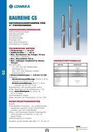
28<br />
FLOW RATE<br />
WATER REQUIREMENTS IN CIVIL USERS<br />
NUMBER OF PEOPLE OR BEDS<br />
1 = OFFICES (N. OF PEOPLE) 3 = HOSPITALS (BEDS)<br />
2 = DEPARTMENT STORES (N. OF PEOPLE) *4 = RESIDENTIAL HOTELS (BEDS)<br />
*NOTE = FOR SEASIDE RESORTS CONSIDER A MINIMUM 20% FLOW RATE INCREASE<br />
TECHNI<strong>CA</strong>L APPENDIX
TECHNI<strong>CA</strong>L APPENDIX<br />
NPSH<br />
The minimum operating values that can be reached at<br />
the pump suction end are limited by the onset of<br />
cavitation.<br />
Cavitation is the formation of vapour-filled cavities<br />
within liquids where the pressure is locally reduced to a<br />
critical value, or where the local pressure is equal to, or<br />
just below the vapour pressure of the liquid.<br />
The vapour-filled cavities flow with the current and<br />
when they reach a higher pressure area the vapour<br />
contained in the cavities condenses. The cavities collide,<br />
generating pressure waves that are transmitted to the<br />
walls. These, being subjected to stress cycles, gradually<br />
become deformed and yield due to fatigue. This<br />
phenomenon, characterized by a metallic noise<br />
produced by the hammering on the pipe walls, is called<br />
incipient cavitation.<br />
The damage caused by cavitation may be magnified by<br />
electrochemical corrosion and a local rise in<br />
temperature due to the plastic deformation of the<br />
walls. The materials that offer the highest resistance to<br />
heat and corrosion are alloy steels, especially austenitic<br />
steel. The conditions that trigger cavitation may be<br />
assessed by calculating the total net suction head,<br />
referred to in technical literature with the acronym<br />
NPSH (Net Positive Suction Head).<br />
The NPSH represents the total energy (expressed in m.)<br />
of the liquid measured at suction under conditions of<br />
incipient cavitation, excluding the vapour pressure<br />
(expressed in m.) that the liquid has at the pump inlet.<br />
To find the static height hz at which to install the<br />
machine under safe conditions, the following formula<br />
must be verified:<br />
hp + hz ≥ (NPSHr + 0.5) + hf + hpv ➀<br />
where:<br />
hp is the absolute pressure applied to the free liquid<br />
surface in the suction tank, expressed in m. of<br />
liquid; hp is the quotient between the barometric<br />
pressure and the specific weight of the liquid.<br />
hz is the suction lift between the pump axis and the<br />
free liquid surface in the suction tank, expressed<br />
in m.; hz is negative when the liquid level is<br />
lower than the pump axis.<br />
hf is the flow resistance in the suction line and its<br />
accessories, such as: fittings, foot valve, gate<br />
valve, elbows, etc.<br />
hpv is the vapour pressure of the liquid at the<br />
operating temperature, expressed in m. of<br />
liquid. hpv is the quotient between the Pv vapour<br />
pressure and the liquid's specific weight.<br />
0.5 is the safety factor.<br />
The maximum possible suction head for installation<br />
depends on the value of the atmospheric pressure<br />
(i.e. the elevation above sea level at which the pump<br />
is installed) and the temperature of the liquid.<br />
To help the user, with reference to water temperature<br />
(4°C) and to the elevation above sea level, the<br />
following tables show the drop in hydraulic pressure<br />
head in relation to the elevation above sea level, and<br />
the suction loss in relation to temperature.<br />
Water<br />
20 40 60 80 90 110 120<br />
temperature (°C)<br />
Suction<br />
loss (m)<br />
Elevation above<br />
sea level (m)<br />
Suction<br />
loss (m)<br />
0,2 0,7 2,0 5,0 7,4 15,4 21,5<br />
500 1000 1500 2000 25003000<br />
0,55 1,1 1,65 2,2 2,75 3,3<br />
Flow resistance is shown in the tables at pages 31-32<br />
of this catalogue. To reduce it to a minimum,<br />
especially in cases of high suction head (over 4-5 m.)<br />
or within the operating limits with high flow rates, we<br />
recommend using a suction line having a larger<br />
diameter than that of the pump's suction port.<br />
It is always a good idea to position the pump as close<br />
as possible to the liquid to be pumped.<br />
Make the following calculation:<br />
Liquid: water at 15°C y = 1 kg/dm 3<br />
Flow rate required: 30 m 3 /h<br />
Head for required delivery: 43 m.<br />
Suction lift: 3.5 m.<br />
The selection is an FHE 40-200/75 pump whose NPSH<br />
required value is, at 30 m 3 /h, 2.5 m.<br />
For water at 15°C the hpv term is Pv = 0,174 m (0.01701 bar)<br />
<br />
and h = Pa = 10,33m<br />
<br />
The Hf flow resistance in the suction line with foot<br />
valves is 1.2 m.<br />
By substituting the parameters in formula ¿ with the<br />
numeric values above, we have:<br />
10,33 + (-3,5) ≥ (2,5 + 0,5) + 1,2 + 0,17<br />
from which we have: 6.8 > 4.4<br />
The relation is therefore verified.<br />
29
TECHNI<strong>CA</strong>L APPENDIX<br />
ps VAPOUR PRESSURE AND DENSITY OF WATER TABLE<br />
TABELLA TENSIONE DI VAPORE ps E DENSITÀ ρ DELL’ACQUA<br />
t T ps ρ<br />
t T ps ρ<br />
t T ps ρ<br />
°C K bar kg/dm 3 °C K bar kg/dm 3 °C K bar kg/dm 3<br />
0 273,15 0,00611 0,9998<br />
1 274,15 0,00657 0,9999<br />
2 275,15 0,00706 0,9999<br />
3 276,15 0,00758 0,9999<br />
4 277,15 0,00813 1,0000<br />
5 278,15 0,00872 1,0000<br />
6 279,15 0,00935 1,0000<br />
7 280,15 0,01001 0,9999<br />
8 281,15 0,01072 0,9999<br />
9 282,15 0,01147 0,9998<br />
10 283,15 0,01227 0,9997<br />
11 284,15 0,01312 0,9997<br />
12 285,15 0,01401 0,9996<br />
13 286,15 0,01497 0,9994<br />
14 287,15 0,01597 0,9993<br />
15 288,15 0,01704 0,9992<br />
16 289,15 0,01817 0,9990<br />
17 290,15 0,01936 0,9988<br />
18 291,15 0,02062 0,9987<br />
19 292,15 0,02196 0,9985<br />
20 293,15 0,02337 0,9983<br />
21 294,15 0,2485 0,9981<br />
22 295,15 0,02642 0,9978<br />
23 296,15 0,02808 0,9976<br />
24 297,15 0,02982 0,9974<br />
25 298,15 0,03166 0,9971<br />
26 299,15 0,03360 0,9968<br />
27 300,15 0,03564 0,9966<br />
28 301,15 0,03778 0,9963<br />
29 302,15 0,04004 0,9960<br />
30 303,15 0,04241 0,9957<br />
31 304,15 0,04491 0,9954<br />
32 305,15 0,04753 0,9951<br />
33 306,15 0,05029 0,9947<br />
34 307,15 0,05318 0,9944<br />
35 308,15 0,05622 0,9940<br />
36 309,15 0,05940 0,9937<br />
37 310,15 0,06274 0,9933<br />
38 311,15 0,06624 0,9930<br />
39 312,15 0,06991 0,9927<br />
40 313,15 0,07375 0,9923<br />
41 314,15 0,07777 0,9919<br />
42 315,15 0,08198 0,9915<br />
43 316,15 0,09639 0,9911<br />
44 317,15 0,09100 0,9907<br />
45 318,15 0,09582 0,9902<br />
46 319,15 0,10086 0,9898<br />
47 320,15 0,10612 0,9894<br />
48 321,15 0,11162 0,9889<br />
49 322,15 0,11736 0,9884<br />
50 323,15 0,12335 0,9880<br />
51 324,15 0,12961 0,9876<br />
52 325,15 0,13613 0,9871<br />
53 326,15 0,14293 0,9862<br />
54 327,15 0,15002 0,9862<br />
55 328,15 0,15741 0,9857<br />
56 329,15 0,16511 0,9852<br />
57 330,15 0,17313 0,9846<br />
58 331,15 0,18147 0,9842<br />
59 332,15 0,19016 0,9837<br />
60 333,15 0,19920 0,9232<br />
61 334,15 0,2086 0,9826<br />
62 335,15 0,2184 0,9821<br />
63 336,15 0,2286 0,9816<br />
64 337,15 0,2391 0,9811<br />
65 338,15 0,2501 0,9805<br />
66 339,15 0,2615 0,9799<br />
67 340,15 0,2733 0,9793<br />
68 341,15 0,2856 0,9788<br />
69 342,15 0,2984 0,9782<br />
70 343,15 0,3116 0,9777<br />
71 344,15 0,3253 0,9770<br />
72 345,15 0,3396 0,9765<br />
73 346,15 0,3543 0,9760<br />
74 347,15 0,3696 0,9753<br />
75 348,15 0,3855 0,9748<br />
76 349,15 0,4019 0,9741<br />
77 350,15 0,4189 0,9735<br />
78 351,15 0,4365 0,9729<br />
79 352,15 0,4547 0,9723<br />
80 353,15 0,4736 0,9716<br />
81 354,15 0,4931 0,9710<br />
82 355,15 0,5133 0,9704<br />
83 356,15 0,5342 0,9697<br />
84 357,15 0,5557 0,9691<br />
85 358,15 0,5780 0,9684<br />
86 359,15 0,6011 0,9678<br />
87 360,15 0,6249 0,9671<br />
88 361,15 0,6495 0,9665<br />
89 362,15 0,6749 0,9658<br />
90 363,15 0,7011 0,9652<br />
91 364,15 0,7281 0,9644<br />
92 365,15 0,7561 0,9638<br />
93 366,15 0,7849 0,9630<br />
94 367,15 0,8146 0,9624<br />
95 368,15 0,8453 0,9616<br />
96 369,15 0,8769 0,9610<br />
97 370,15 0,9094 0,9602<br />
98 371,15 0,9430 0,9596<br />
99 372,15 0,9776 009586<br />
100 373,15 1,0133 0,9581<br />
102 375,15 1,0878 0,9567<br />
104 377,15 1,1668 0,9552<br />
106 379,15 1,2504 0,9537<br />
108 381,15 1,3390 0,9522<br />
110 383,15 1,4327 0,9507<br />
112 385,15 1,5316 0,9491<br />
114 387,15 1,6362 0,9476<br />
116 389,15 1,7465 0,9460<br />
118 391,15 1,8628 0,9445<br />
120 393,15 1,9854 0,9429<br />
122 395,15 2,1145 0,9412<br />
124 397,15 2,2504 0,9396<br />
126 399,15 2,3933 0,9379<br />
128 401,15 2,5435 0,9362<br />
130 403,15 2,7013 0,9346<br />
132 405,15 2,8670 0,9328<br />
134 407,15 3,041 0,9311<br />
136 409,15 3,223 0,9294<br />
138 411,15 3,414 0,9276<br />
140 413,15 3,614 0,9258<br />
145 418,15 4,155 0,9214<br />
150 423,15 4,760 0,9168<br />
155 428,15 5,433 0,9121<br />
160 433,15 6,181 0,9073<br />
165 438,15 7,008 0,9024<br />
170 433,15 7,920 0,8973<br />
175 448,15 8,924 0,8921<br />
180 453,15 10,027 0,8869<br />
185 458,15 11,233 0,8815<br />
190 463,15 12,551 0,8760<br />
195 468,15 13,987 0,8704<br />
200 473,15 15,55 0,8647<br />
205 478,15 17,243 0,8588<br />
210 483,15 19,077 0,8528<br />
215 488,15 21,060 0,8467<br />
220 493,15 23,198 0,8403<br />
225 498,15 25,501 0,8339<br />
230 503,15 27,976 0,8273<br />
235 508,15 30,632 0,8205<br />
240 513,15 33,478 0,8136<br />
245 518,15 36,523 0,8065<br />
250 523,15 39,776 0,7992<br />
255 528,15 43,246 0,7916<br />
260 533,15 46,943 0,7839<br />
265 538,15 50,877 0,7759<br />
270 543,15 55,058 0,7678<br />
275 548,15 59,496 0,7593<br />
280 553,15 64,202 0,7505<br />
285 558,15 69,186 0,7415<br />
290 563,15 74,461 0,7321<br />
295 568,15 80,037 0,7223<br />
300 573,15 85,927 0,7122<br />
305 578,15 92,144 0,7017<br />
310 583,15 98,700 0,6906<br />
315 588,15 105,61 0,6791<br />
320 593,15 112,89 0,6669<br />
325 598,15 120,56 0,6541<br />
330 603,15 128,63 0,6404<br />
340 613,15 146,05 0,6102<br />
350 623,15 165,35 0,5743<br />
360 633,15 186,75 0,5275<br />
370 643,15 210,54 0,4518<br />
374,15 647,30 221,2 0,3154<br />
30
TECHNI<strong>CA</strong>L APPENDIX<br />
TABLE OF FLOW RESISTANCE IN 100 m OF A NEW AND<br />
STRAIGHT <strong>CA</strong>ST IRON PIPELINE<br />
FLOW PORTATA RATE<br />
DIAMETRO NOMINAL NOMINALE DIAMETER IN mm IN mm E IN AND POLLICI INCHES<br />
m 3 /h l/min. 15 20 25 32 40 50 65 80 100 125 150 175 200 250 300 350 400<br />
1<br />
/2” 3<br />
/4” 1” 1 1 /4” 1 1 /2” 2” 2 1 /2” 3” 4” 5” 6” 7” 8” 10” 12” 14” 16”<br />
0,6 10<br />
0,9 15<br />
1,2 20<br />
1,5 25<br />
1,8 30<br />
2,1 35<br />
2,4 40<br />
3 50<br />
3,6 60<br />
4,2 70<br />
4,8 80<br />
5,4 90<br />
6 100<br />
7,5 125<br />
9 150<br />
10,5 175<br />
12 200<br />
15 250<br />
18 300<br />
24 400<br />
30 500<br />
36 600<br />
42 700<br />
48 800<br />
54 900<br />
60 1000<br />
75 1250<br />
90 1500<br />
105 1750<br />
120 2000<br />
150 2500<br />
180 3000<br />
300 5000<br />
600 10000<br />
1200 20000<br />
1800 30000<br />
3000 50000<br />
4500 75000<br />
6000 100000<br />
V V = WATER VELOCITÀ SPEED DELL’ACQUA (m/sec) (m/sec) Hr hr = PERDITA FLOW RESISTANCE DI <strong>CA</strong>RICO (m/100 m DI m TUBAZIONE) OF PIPELINE)<br />
V 0,94 0,53 0,34 0,21<br />
hr 11,8 2,82 1 0,25<br />
V 1,42 0,8 0,51 0,31<br />
hr 25,1 6,04 2,16 0,55<br />
THE LE PERDITE FLOW RESISTANCE DI <strong>CA</strong>RICO DEVONO MUST ESSERE BE MULTIPLIED MOLTIPLI<strong>CA</strong>TE BY: PER:<br />
V 1,89 1,06 0,68 0,41 0,27<br />
• 0,8 0.8 for per stainless tubi acciaio steel inox pipes<br />
• 1,25 1.25 per for tubi slightly in acciaio rusted leggermente steel pipes arrugginiti<br />
hr 43,1 10,4 3,72 0,95 0,31<br />
• 1,7 1.7 for per pipes tubi con with incrostazioni deposits that che riducono reduce the la sezione flow section di passaggio<br />
V 2,36 1,33 0,85 0,52 0,33<br />
• 0,7 0.7 for per aluminium tubi di alluminio pipes<br />
hr 64,5 15,8 5,68 1,47 0,47<br />
• 1,3 1.3 for per fibre-cement tubi in fibra di pipes cemento<br />
V 2,83 1,59 1,02 0,62 0,4<br />
hr 92 22,3 8 2,09 0,66<br />
V 3,3 1,86 1,19 0,73 0,46 0,3<br />
hr 123 29,8 10,8 2,81 0,89 0,31<br />
V 3,77 2,12 1,36 0,83 0,53 0,34<br />
hr 164 38,2 13,8 2,65 1,15 0,4<br />
V 4,72 2,65 1,7 1,04 0,66 0,42<br />
hr 246 58,2 21,5 5,6 1,75 0,61<br />
V 3,18 2,04 1,24 0,8 0,51<br />
hr 82 30 8 2,48 0,86<br />
V 3,72 2,38 1,45 0,93 0,59<br />
hr 110 40 10,8 3,33 1,14<br />
V 4,25 2,72 1,66 1,06 0,68<br />
hr 141 51,5 13,9 4,3 1,46<br />
V 3,06 1,87 1,19 0,76 0,45<br />
hr 64 17,5 5,4 1,82 0,46<br />
V 3,4 2,07 1,33 0,85 0,5<br />
hr 79 21,4 6,6 2,22 0,56<br />
V 4,25 2,59 1,66 1,06 0,63<br />
hr 120 33 10 3,4 0,86<br />
V 3,11 1,99 1,27 0,75 0,5<br />
hr 47 14,2 4,74 1,21 0,43<br />
V 3,63 2,32 1,49 0,88 0,58<br />
hr 63 19 6,3 1,63 0,57<br />
V 4,15 2,65 1,7 1,01 0,66<br />
hr 82 24,5 8,1 2,1 0,74<br />
V 5,18 3,32 2,12 1,26 0,83 0,53<br />
hr 126 37,5 12,3 3,2 1,12 0,36<br />
V 3,98 2,55 1,51 1 0,64<br />
hr 53 17,3 4,5 1,58 0,51<br />
V 5,31 3,4 2,01 1,33 0,85<br />
hr 92 29,5 7,8 2,7 0,89<br />
V 6,63 4,25 2,51 1,66 1,06 0,68<br />
hr 140 44,8 12 4,13 1,36 0,48<br />
V 5,1 3,02 1,99 1,27 0,82<br />
hr 63 16,9 5,8 1,93 0,68<br />
V 5,94 3,52 2,32 1,49 0,95<br />
hr 84 22,6 7,8 2,6 0,9<br />
V 6,79 4,02 2,65 1,70 1,09 0,75<br />
hr 108 29 10 3,35 1,16 0,43<br />
V 7,64 4,52 2,99 1,91 1,22 0,85<br />
hr 134 36 12,5 4,2 1,45 0,54<br />
V 5,03 3,32 2,12 1,36 0,94<br />
hr 44,5 15,2 5,14 1,76 0,66<br />
V 6,28 4,15 2,65 1,70 1,18 0,87<br />
hr 68 23 7,9 2,68 1 0,48<br />
V 7,54 4,98 3,18 2,04 1,42 1,04<br />
hr 96 32,6 11,2 3,77 1,42 0,68<br />
V 8,79 5,81 3,72 2,38 1,65 1,21 0,93<br />
hr 129 43,5 15 5,04 1,9 0,91 0,45<br />
V 6,63 4,25 2,72 1,89 1,39 1,06 0,68<br />
hr 56 19,4 6,5 2,43 1,18 0,58 0,16<br />
V 8,29 5,31 3,40 2,36 1,73 1,33 0,85<br />
hr 85 30 9,8 3,75 1,79 0,89 0,25<br />
V 9,95 6,37 4,08 2,83 2,08 1,59 1,02 0,71<br />
hr 120 42 13,8 5,3 2,53 1,25 0,35 0,15<br />
V 10,62 6,79 4,72 3,47 2,65 1,70 1,18 0,87 0,66<br />
hr 124,9 41,3 16,74 7,81 4,03 1,34 0,54 0,25 0,13<br />
V 13,59 9,44 6,93 5,31 3,4 2,36 1,73 1,33<br />
hr 161 65 30,2 15,6 5,16 2,09 0,97 0,5<br />
V 6,79 4,72 3,47 2,65<br />
hr 20,1 8,13 3,8 1,95<br />
V 7,7 5,2 4,0<br />
hr 18,07 8,39 4,32<br />
V 11,8 8,67 6,63<br />
hr 49,5 23 11,8<br />
V 17,7 13 9,9<br />
hr 110,5 51,3 26,4<br />
V 17,33 13,27<br />
hr 90,6 46,6<br />
31
TECHNI<strong>CA</strong>L APPENDIX<br />
TABLE TABELLA OF PERDITE FLOW DI RESISTANCE <strong>CA</strong>RICO NELLE IN CURVE, BENDS, VALVOLE VALVES E SARACINESCHE<br />
AND<br />
GATES IN cm DIIN COLONNA cm OF D’ACQUA COLUMN OF WATER<br />
VELOCITÀ WATER<br />
CURVE SHARP AD ANGOLO BENDSVIVO SMOOTH CURVE NORMALI BENDS STANDARD SARACI- VALVO- FOOT VALVO- CHECK<br />
DELL’ACQUA SPEED<br />
NESCHE GATE VALVES LE DI VALVES LE DI<br />
NORMALI VALVES FONDO RITEGNO<br />
m/sec a = 30° a = 40° a = 60° a = 80° a = 90°<br />
d d = 0,4<br />
d = 0,6<br />
d = 0,8 = 1<br />
d = 1,5<br />
R R R R R<br />
0,10 0,03 0,04 0,05 0,07 0,08 0,007 0,008 0,01 0,0155 0,027 0,030 30 30<br />
0,15 0,06 0,07 0,10 0,14 0,17 0,016 0,019 0,024 0,033 0,06 0,033 31 31<br />
0,2 0,11 0,13 0,18 0,26 0,31 0,028 0,033 0,04 0,058 0,11 0,058 31 31<br />
0,25 0,17 0,21 0,28 0,4 0,48 0,044 0,052 0,063 0,091 0,17 0,090 31 31<br />
0,3 0,25 0,30 0,41 0,6 0,7 0,063 0,074 0,09 0,13 0,25 0,13 31 31<br />
0,35 0,33 0,40 0,54 0,8 0,93 0,085 0,10 0,12 0,18 0,33 0,18 31 31<br />
0,4 0,43 0,52 0,71 1,0 1,2 0,11 0,13 0,16 0,23 0,43 0,23 32 31<br />
0,5 0,67 0,81 1,1 1,6 1,9 0,18 0,21 0,26 0,37 0,67 0,37 33 32<br />
0,6 0,97 1,2 1,6 2,3 2,8 0,25 0,29 0,36 0,52 0,97 0,52 34 32<br />
0,7 1,35 1,65 2,2 3,2 3,9 0,34 0,40 0,48 0,70 1,35 0,70 35 32<br />
0,8 1,7 2,1 2,8 4,0 4,8 0,45 0,53 0,64 0,93 1,7 0,95 36 33<br />
0,9 2,2 2,7 3,6 5,2 6,2 0,57 0,67 0,82 1,18 2,2 1,20 37 34<br />
1,0 2,7 3,3 4,5 6,4 7,6 0,7 0,82 1,0 1,45 2,7 1,45 38 35<br />
1,5 6,0 7,3 10 14 17 1,6 1,9 2,3 3,3 6 3,3 47 40<br />
2,0 11 14 18 26 31 2,8 3,3 4,0 5,8 11 5,8 61 48<br />
2,5 17 21 28 40 48 4,4 5,2 6,3 9,1 17 9,1 78 58<br />
3,0 25 30 41 60 70 6,3 7,4 9 13 25 13 100 71<br />
3,5 33 40 55 78 93 8,5 10 12 18 33 18 123 85<br />
4,0 43 52 70 100 120 11 13 16 23 42 23 150 100<br />
4,5 55 67 90 130 160 14 21 26 37 55 37 190 120<br />
5,0 67 82 110 160 190 18 29 36 52 67 52 220 140<br />
1) Le Flow perdite resistance di carico in nelle bends curve is due sono to soltanto the contraction quelle dovute of the alla liquid contrazione threads dei resulting filetti liquidi from per the cambiamento change of direction: direzione: the lo development sviluppo delle of curve the bends deve quindi<br />
essere must therefore compreso be nella included lunghezza in the della length tubazione. of the pipeline.<br />
2) Le Flow perdite resistance di carico in nelle valves valvole and gates e saracinesche was determined sono state on determinate the basis of in practical base a prove tests. pratiche.<br />
32
TECHNI<strong>CA</strong>L APPENDIX<br />
VOLUMETRIC <strong>CA</strong>PACITY<br />
litres<br />
per minute<br />
cubic metres<br />
per hour<br />
Portata Volumetrica<br />
cubic feet<br />
per hour<br />
cubic feet<br />
per minute<br />
imp. gal. per<br />
minute<br />
US gal. per<br />
minute<br />
l/min m³/h ft³/h ft³/min imp. gal./min US gal./min<br />
1,0000 0,0600 2,1189 0,0353 0,2200 0,2640<br />
16,6670 1,0000 35,3147 0,5886 3,6660 4,4030<br />
0,4720 0,0283 1,0000 0,0167 0,1040 0,1250<br />
28,3170 1,6990 60,0000 1,0000 6,2290 7,4800<br />
4,5460 0,2728 9,6326 0,1605 1,0000 1,2010<br />
3,7850 0,2271 8,0209 0,1337 0,8330 1,0000<br />
0,1100 0,0066 0,2339 0,0039 0,0240 0,0290<br />
PRESSURE AND HEAD<br />
Newton per square<br />
metre<br />
Pressione e Prevalenza<br />
kiloPascal bar pound force per<br />
square inch<br />
metre of water<br />
millimetre of<br />
mercury<br />
N/m² kPa bar psi m H 2 O mm Hg<br />
1,0000 0,0010 1 x 10 5 1,45 x 10 -4 1,02 x 10 -4 0,0075<br />
1.000,0000 1,0000 0,0100 0,1450 0,1020 7,5000<br />
100.000,0000 100,0000 1,0000 14,5000 10,2000 750,1000<br />
98.067,0000 98,0700 0,9810 14,2200 10,0000 735,6000<br />
6.895,0000 6,8950 0,0690 1,0000 0,7030 51,7200<br />
2.984,0000 2,9840 0,0300 0,4330 0,3050 22,4200<br />
9.789,0000 9,7890 0,0980 1,4200 1,0000 73,4200<br />
133,3000 0,1330 0,0013 0,0190 0,0140 1,0000<br />
3.386,0000 3,3860 0,0338 0,4910 0,3450 25,4000<br />
LENGTH<br />
Lunghezza<br />
millimetre centimetre metre inch foot yard<br />
mm cm m in ft yd<br />
1,0000 0,1000 0,0010 0,0394 0,0033 0,0011<br />
10,0000 1,0000 0,0100 0,3937 0,0328 0,0109<br />
1000,0000 100,0000 1,0000 39,3701 3,2808 1,0936<br />
25,4000 2,5400 0,0254 1,0000 0,0833 0,0278<br />
304,8000 30,4800 3,0480 12,0000 1,0000 0,3333<br />
914,4000 91,4400 0,9144 36,0000 3,0000 1,0000<br />
VOLUME<br />
Volume<br />
cubic metre litre millilitre imp. gallon US gallon cubic foot<br />
m³ l ml imp. gal. US gal ft³<br />
1,0000 1.000,0000 1 x 10 6 220,0000 264,2000 35,3147<br />
0,0010 1,0000 1.000,0000 0,2200 0,2642 0,0353<br />
1 x 10 -6 0,0010 1,0000 2,2 x 10 -4 2,642 x 10 -4 3,53 x 10 -5<br />
0,0045 4,5460 4.546,0000 1,0000 1,2010 0,1605<br />
0,0038 3,7850 3.785,0000 0,8327 1,0000 0,1337<br />
0,0283 28,3170 28.317,0000 6,2288 7,4805 1,0000<br />
33
®<br />
RECYCLED<br />
PAPER<br />
Do it 100%<br />
ORGANIZZAZIONE COMMERCIALE ITALIA – ITALIAN SALES NETWORK<br />
BARI<br />
70026 Modugno Bari<br />
Via X Marzo, 110 P<br />
Tel. 080 5327453 - 5353808<br />
Fax: 080 5327926<br />
e-mail: bari@lowara.ittind.com<br />
BOLOGNA<br />
40132 Bologna - Via Panigale, 74/C<br />
Tel. 051 6415666<br />
Fax: 051 6415527<br />
e-mail: bologna@lowara.ittind.com<br />
BRESCIA<br />
25124 Brescia - Via Volta, 37<br />
Tel. 030 3531909<br />
Fax: 030 3534661<br />
e-mail: brescia@lowara.ittind.com<br />
<strong>CA</strong>GLIARI<br />
09100 Cagliari - Via Dolcetta, 19<br />
Tel. 070 287762 - 292192<br />
Fax: 070 280946<br />
e-mail: cagliari@lowara.ittind.com<br />
<strong>CA</strong>TANIA<br />
95027 S. Gregorio - Catania<br />
Via XX Settembre, 75<br />
Tel. 095 7123226 - 7123987<br />
Fax: 095 498902<br />
e-mail: catania@lowara.ittind.com<br />
CHIETI<br />
PISA<br />
66020 Sambuceto di S. Giovanni Teatino<br />
Via Aldo Moro, 125<br />
Tel. 085 4461360 - 4460231 - 4460449<br />
Fax 085 4460630<br />
e-mail: pescara@lowara.ittind.com<br />
MILANO<br />
20090 Trezzano sul Naviglio Milano<br />
Via Goldoni, 29<br />
Tel. 02 48464476 - Fax: 02 4451634<br />
e-mail: milano@lowara.ittind.com<br />
NAPOLI<br />
80017 Melito di Napoli - Napoli<br />
Corso Europa, 369 - Scala “A” int. 11-12<br />
Tel. 081 7113065 - 7113631<br />
Fax: 081 7115761<br />
e-mail: napoli@lowara.ittind.com<br />
PADOVA<br />
35020 Albignasego - Via A. Volta, 56<br />
Zona Mandriola<br />
Tel. 049 8801110 - 8801408<br />
Fax: 049 8801408<br />
e-mail: bassano@lowara.ittind.com<br />
PERUGIA<br />
06100 Perugia<br />
Via Settevalli, 133C, Torre 2 - 3° Piano<br />
Centro Direzionale Piazza Settevalli<br />
Tel. 075 5057126 - Fax: 075 5051242<br />
e-mail: perugia@lowara.ittind.com<br />
56025 Località Gello di Pontedera - Pisa<br />
Via di Gello, 55<br />
Tel. 0587 296264 - 296286<br />
Fax: 0587 296410<br />
e-mail: pisa@lowara.ittind.com<br />
PORDENONE<br />
33082 Azzano Decimo Pordenone<br />
Viale 1° Maggio, 65/1 Area 53<br />
Tel. 0434 633243 - Fax: 0434 632729<br />
e-mail: pordenone@lowara.ittind.com<br />
ROMA<br />
00173 Roma - Via Frascineto, 8<br />
Tel. 06 7235890 (2 linee)<br />
Fax: 06 7234617<br />
e-mail: roma@lowara.ittind.com<br />
TORINO<br />
Via Torre Pellice, 17 - 10156 Torino<br />
Tel. 011 2979022 - 2979046<br />
Fax: 011 2979001<br />
e-mail: torino@lowara.ittind.com<br />
VICENZA<br />
36061 Bassano del Grappa - VI<br />
Via Pigafetta, 6<br />
Tel. 0424 566776 (R.A. 3 Linee)<br />
Fax: 0424 566773<br />
e-mail: bassano@lowara.ittind.com<br />
ORGANIZZAZIONE COMMERCIALE EUROPA – EUROPEAN SALES NETWORK<br />
LOWARA DEUTSCHLAND GmbH<br />
Biebigheimer Straße 12<br />
63762 Großostheim - (OT Wenigumstadt) - D<br />
Tel. 0 60 26 9 43 - 0<br />
Fax: 0 60 26 9 43 - 2 10<br />
e-mail: info.de@lowara.ittind.com<br />
http://www.lowara.de<br />
LOWARA FRANCE S.A.S.<br />
BP 7311 - 37073 TOURS CEDEX 2 - F<br />
Tel. (0033) 02 47 88 17 17<br />
Fax: (0033) 02 47 88 17 00<br />
e-mail: info.fr@lowara.ittind.com<br />
http://www.lowara.fr<br />
LOWARA NEDERLAND B.V.<br />
POSTBUS 54 - 4180 BB Waardenburg<br />
Tel. 0031 - (0)418 - 65 50 60<br />
Fax: 0031 - (0)418 - 65 50 61<br />
e-mail: info.nl@lowara.ittind.com<br />
http://www.lowara.nl<br />
LOWARA PORTUGAL, Lda<br />
Praceta da Castanheira, 38<br />
4475-019 Barca Portugal<br />
Tel. 00351 22 9478550<br />
Fax: 00351 22 9478570<br />
e-mail: info.pt@lowara.ittind.com<br />
http://www.lowara.pt<br />
LOWARA UK Ltd. Main office<br />
Millwey Rise Industrial Estate -<br />
Axminster, Devon EX 13 5HU - GB<br />
Tel. 01297 630200 - Fax: 01297 630270<br />
e-mail: uksales@lowara.ittind.com<br />
http://www.lowara.co.uk<br />
LOWARA UK Ltd. Regional sales office<br />
Unit 1, Byram Industrial Park - Low Street<br />
Brotherton, Knottingley - West Yorkshire WF11 9HS<br />
Tel. 01977 607267 - Fax 01977 607226<br />
e-mail: salesuknorth@lowara.ittind.com<br />
http://www.lowara.co.uk<br />
LOWARA IRELAND Ltd.<br />
59 Broomhill Drive - Tallaght Industrial Estate<br />
Tallaght - DUBLIN 24 - EIRE<br />
Tel. (1) 4520266 - Fax: (1) 4520725<br />
e-mail: sales-irl@lowara.ittind.com<br />
http://www.lowara.ie<br />
LOWARA S.r.l. - 36075 Montecchio Maggiore - Vicenza - Italy - Tel. +39 0444/707111 - Telefax +39 0444/492166 - e-mail: mkt@lowara.ittind.com - http://www.lowara.com<br />
LOWARA si riserva il diritto di apportare modifiche senza obbligo di preavviso — LOWARA reserves the right to make modifications without prior notice<br />
cod. 191013751 09/03