MK4 VW instructions.pdf - APR
MK4 VW instructions.pdf - APR
MK4 VW instructions.pdf - APR

Create successful ePaper yourself
Turn your PDF publications into a flip-book with our unique Google optimized e-Paper software.
INSTALLATION INSTRUCTIONS FOR 1999.5-2004<br />
<strong>MK4</strong> VOLKSWAGEN JETTA (BORA) /GOLF 1.8T, 2.0L, VR6, & R32 MODELS<br />
ALSO FITS ALL MODELS OF SEAT LEON & TOLEDO<br />
Thank you for choosing to purchase a Carbonio Intake System. Please take the<br />
time to fully read over these <strong>instructions</strong> before attempting to install the kit. This<br />
will greatly speed up the installation process and minimize any difficulties you<br />
may encounter.<br />
Tools Required:<br />
- Socket wrench with extensions and 10mm and 13mm socket heads<br />
- Flat headed (slot) screwdriver<br />
- Channel lock (or similar) pliers<br />
- Scissors or wire cutters<br />
- 10mm open-ended wrench<br />
- Phillips head (star) screwdriver<br />
- 3mm Allen (hex) wrench<br />
Kit includes:<br />
1 - Carbon Fibre main intake section<br />
1 - Air filter (pre-oiled)<br />
1 - alloy intake snorkel<br />
1 - silicone coupler<br />
4 - 3” hose clamps<br />
1 - Small breather filter<br />
1 - Small hose clamp<br />
1 - MAF coupling<br />
2 - Black nylon tie straps<br />
1 - Rubber lined steel body fixing clamp<br />
LABOUR ESTIMATE GUIDE<br />
1.25 Hours
Note: These <strong>instructions</strong> depict images of a <strong>MK4</strong> VR6 engine compartment. The 2.0L, 1.8T, &<br />
R32 are sufficiently similar in their intake layout to use these images.<br />
Step 1:<br />
Remove the battery by following this order:<br />
1- Remove the top cover of the battery box (snapped in place; requires no tools)<br />
2- Disconnect the negative ( - ) battery terminal.<br />
3- Disconnect the positive (+) battery terminal.<br />
4- Remove the entire battery box (it is snap fit in place and requires the removal of no<br />
fasteners to disassemble)<br />
5- Remove the single 13mm bolt and metal fixing plate that is along the forward facing<br />
bottom edge of the battery.<br />
6- Lift the battery out.<br />
Also, using a 10mm socket, remove the 4 bolts that hold the battery tray in place and remove the<br />
tray.<br />
NOTE: Make sure you have your radio code handy and note your radio presets so that they can<br />
be re-programmed later if necessary<br />
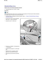
Step 2:<br />
Using a Phillips head screwdriver, fully loosen the two screws that are on the backside of the<br />
airbox lid. These screws stay in the cover and do not need to be removed.<br />
Step 3:<br />
Disconnect the electrical connecter that leads to the mass airflow meter. Do this by pulling back<br />
on the tab on the top of the connector while pulling it away from its socket.
Step 4:<br />
Using a pair of pliers, remove the clamp that<br />
connects the mass air sensor to the induction<br />
hose that leads to the engine. Do this by<br />
compressing the two tabs on the clamp<br />
together and sliding the clamp over the hose.<br />
Tip: leaving the clamp over the hose makes it<br />
much easier to re-install later.<br />
Step 5:<br />
Separate the hose that leads to the mass air sensor and remove the cover of the airbox by tilting<br />
it towards the front of the car to disconnect the two tabs that join the cover to the main box.<br />
Step 6 (may not be necessary on some vehicles):<br />
Remove the corrugated breather hose that is connected to the airbox cover. Do this by squeezing<br />
on the ribbed portions of the clamp that surround the hose with your fingers and pulling sharply<br />
apart.<br />
NOTE: Vehicles sold in some countries will not have this corrugated breather hose however they<br />
may have a temperature sensor leading to the side of the airbox. If your car has this sensor, you<br />
must unclip it from the airbox and, using the black plastic tie straps supplied, fix the sensor<br />
somewhere neat and out of the way in the engine compartment. Recommended areas include,<br />
passing hoses or wires (not ignition wires). Another point of fixing can be one of the mounting<br />
screw holes (no longer used) on the mass airflow sensor.<br />
Step 7:<br />
Using a 10mm socket, remove the two bolts that hold the main airbox in place. Once this is done<br />
remove the airbox. Note: There is a pin on the driver’s side that the airbox is slipped into. Take<br />
note of this when removing the airbox because it can hamper its removal.<br />
Step 8:<br />
Using a 10mm socket, remove the nut holding<br />
the intake snorkel on the side of the engine<br />
compartment. Note: SAVE THIS NUT!!! It will be<br />
used later in the install.
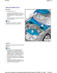
Step 9:<br />
Using a Phillips head screwdriver, remove the two<br />
screws on the plastic cover marked with the light<br />
bulb. This cover is located directly in front of the<br />
battery. Once this is done, remove this cover by<br />
pulling it straight out.<br />
Step 10:<br />
Using a Phillips screwdriver, remove the two screws that hold on the shroud in front of the engine<br />
(this piece is located next to the cover removed in step 9). Once this is done, pull this piece out.<br />
Step 11:<br />
In front of the battery is a plastic shroud held on by three<br />
plastic rivets. These can be very difficult to remove and it<br />
is easiest to use a flat head screwdriver and some force<br />
to break them off. Tugging on the shroud also helps and<br />
if it breaks, this is not a problem because this piece will<br />
no longer be needed. If you do not wish to damage the<br />
shroud by forcing it off, you can knock out the centres of<br />
the three plastic rivets that hold the shroud in place and<br />
remove it this way using very little force. This method can<br />
be time consuming, as the bottom rivet is very difficult to<br />
see.<br />
Step 12 (optional in some instances):<br />
In front of where the battery resides, there is a nut with<br />
cables leading to it. This is a ground connection and the<br />
cables leading from it may be in your way. It is ok to loosen<br />
this nut, turn the wires out of the way, and then re-tighten<br />
the nut. This will give you some more room to route the<br />
intake.
Step 13:<br />
On the inside of the fender, behind the headlight,<br />
there is a plastic connector with one or two wires<br />
leading to it. Slide this connector vertically off of the<br />
plastic bracket that holds it to the inside of the<br />
fender and remove the bracket from the inside of<br />
the fender (it can be tight). Next, unscrew and<br />
remove the cable routing bracket (shown left).<br />
The cable removed in this step, eventually tucks<br />
under the carbon fibre intake tube.<br />
Step 14:<br />
Using a Phillips head screwdriver, remove the two screws that hold the mass airflow sensor to the<br />
cover of the airbox (removed in step 5). Once this is done, remove the mass air sensor by pulling<br />
it apart from the cover.<br />
Step 15:<br />
Slip the included MAF rubber adapter 1” over<br />
the MESH SIDE!!!!! (This is the side with the<br />
square holed grille) of the mass airflow sensor<br />
and fix it using a hose clamp. You may tighten<br />
the hose clamp at this point.<br />
Step 16:<br />
Using pliers, re-install the mass air sensor. Installation is the reverse of Step #4. Once this is<br />
done, re-connect the wire to the mass air sensor that was removed in Step #3.
Step 17 (may not be necessary on some vehicles):<br />
Remove the end fitting from the breather hose removed<br />
in step #6. This may be a very tight fit but some firm<br />
pulling will separate the end from the hose.<br />
Step 18 (may not be necessary on some vehicles):<br />
Install the small breather filter by pushing its open end<br />
into the breather hose. Make sure to push the filter all the<br />
way in until the hose touches the base of the breather<br />
filter. Use the small hose clamp to fix this assembly<br />
together.<br />
Step 19 (may not be necessary on some vehicles):<br />
Using the black plastic tie straps supplied, fix the breather hose somewhere neat and out of the<br />
way in the engine compartment. Recommended areas include, passing hoses or wires (not<br />
ignition wires). Another point of fixing can be one of the mounting screw holes (no longer used)<br />
on the mass airflow sensor.<br />
Step 20:<br />
Slide the rubber and steel clamp over the carbon<br />
pipe with its tab facing up and towards the outside<br />
of the pipe’s curve.<br />
Step 21:<br />
Slip a hose clamp over the rubber adapter on the mass air sensor.<br />
Step 22:<br />
Fit the carbon pipe so that the long end slips into the adapter on the mass air sensor, and the<br />
other end runs down next to where the battery goes. Do not tighten the hose clamp around the<br />
silicone adapter at this time.
Step 23:<br />
In Step #8 the intake snorkel was removed. The stud<br />
that this snorkel was mounted to is used to mount the<br />
rubber and steel clamp. Fit this stud through both holes<br />
on the end of this clamp and fix it using the 10mm nut<br />
removed in Step #8. DO NOT TIGHTEN THIS NUT<br />
YET.<br />
Note: The tabs on the rubber and steel clamp may<br />
require a little twisting to fit.<br />
Step 24:<br />
Get in the car and turn the wheels all the way to<br />
the left. Using a 3mm hex (Allen) wrench, remove<br />
the 12 screws that hold the front driver’s side<br />
plastic inner fender well on and remove this<br />
piece. This will expose the inside of the fender<br />
and the mounting location for the filter.<br />
Note: If the vehicle has been lowered or fitted<br />
with larger wheels, it may be necessary to jack<br />
the vehicle slightly in order to get more<br />
clearance. Refer to your owner’s manual for<br />
directions on jacking the car<br />
Step 25 (Building the lower filter assembly):<br />
Step A:<br />
Remove the clear plastic wrap from around the<br />
filter and insert one end of the included alloy<br />
induction horn into the filter. Make sure that the<br />
horn is at least 1 inch into the filter.<br />
Note: The filter comes pre-oiled and requires no<br />
more oil<br />
Step B:<br />
Using a flat headed screwdriver, tighten the hose<br />
clamp that is on the filter.
Step C:<br />
Over the other end of the alloy induction horn,<br />
slip on the included silicone adapter (the one<br />
that is orange on the inside) and tighten down<br />
with a hose clamp.<br />
IMPORTANT NOTE:<br />
Make sure that the silicone adapter slips on at<br />
about 50% depth over the horn. It is important<br />
that this adapter is centered between the alloy<br />
and carbon fiber components<br />
Step 26:<br />
Kneeling next to the front left tire, grab the filter<br />
by the base and feed it up so that the silicone<br />
fitting enters the engine bay where the end of the<br />
carbon fibre pipe is.<br />
Slip the black silicone fitting over the carbon fibre<br />
pipe and tighten the hose clamp to hold<br />
everything together. DO NOT attempt to use<br />
any kind of lubricant to make the connection<br />
easier. Once assembled, the black silicone<br />
sleeve will rest on the inside body of the car and<br />
support the weight of the system.<br />
WARNING: MAKE SURE THAT THE CARBON FIBRE PIPE IS AT LEAST 1” INTO THE<br />
SILICONE SLEEVE BEFORE TIGHTENING.<br />
Step 27:<br />
Re-install the plastic inner fender well in the reverse of Step #24<br />
Step 28:<br />
Using a 10mm wrench, tighten the nut installed in Step #23<br />
Step 29:<br />
Tighten the hose clamp where the carbon fibre tube meets the silicone adapter on the mass air<br />
sensor.<br />
Step 30:<br />
Re-install the battery and battery box,<br />
Step 31:<br />
Re-install the two plastic shrouds removed in Steps #9 & #10.
Step 32 (Not always necessary):<br />
Refer to the owner’s manual for the re-calibration of the power windows and the re-setting of the<br />
radio codes and onboard clock.<br />
Step 33:<br />
IMPORTANT: Start the car and let it IDLE (DO NOT REV THE ENGINE!) for 5 minutes to recalibrate<br />
the computer. After this, the vehicle is fully ready to drive.<br />
A NOTE ON FILTER MAINTENANCE<br />
The filter on your Carbonio Intake is washable and will last for many years if<br />
cleaned periodically. The best way to clean the filter is to remove it and<br />
service it with a commercially available cleaning kit. These kits are very<br />
inexpensive and require that you wash the filter and oil it after it has had the<br />
opportunity to dry. DO NOT OVER-OIL THE FILTER. BE SPARING WITH<br />
THE OIL AS EXCESSIVE OILING CAN LEAD TO DAMAGE TO THE MAF<br />
SENSOR.