Powers Controls - Siemens Building Technologies
Powers Controls - Siemens Building Technologies
Powers Controls - Siemens Building Technologies

You also want an ePaper? Increase the reach of your titles
YUMPU automatically turns print PDFs into web optimized ePapers that Google loves.
Technical Instructions<br />
Document No. 155-016P25<br />
ET 134-22<br />
September 14, 2005<br />
Powers <strong>Controls</strong><br />
Low Temperature Detection<br />
Thermostat<br />
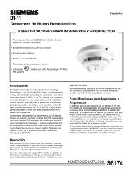
Description<br />
The electric Low Temperature Detection Cut-out and Alarm Thermostat is a remote bulb<br />
instrument which opens an electrical circuit to stop the supply fan motor and/or closes an<br />
outside air damper when the temperature at the sensing element falls below the setting<br />
of the instrument. Simultaneously, it closes a circuit to indicate an alarm condition.<br />
Features • Manual reset<br />
• Easy temperature setting with adjusting screw on top of enclosure<br />
• Mounting bracket and two screws included<br />
• Main and separate reverse-acting auxiliary contacts<br />
Product Number 134-1504<br />
Warning/Caution Notations<br />
WARNING<br />
CAUTION<br />
Personal injury, or loss of life may occur if a<br />
procedure is not performed as specified.<br />
Equipment damage, or loss of data may occur if you<br />
do not follow a procedure as specified.<br />
Application<br />
This instrument should only be used on those applications where the ambient<br />
temperature to which the instrument case and bellows are exposed remains above<br />
the temperature setting of the thermostat. This thermostat should be used in areas<br />
protected from the weather.<br />
<strong>Siemens</strong> Industry, Inc.
Technical Instructions<br />
Document Number 155-016P25<br />
September 14, 2005<br />
Low Temperature Detection Cut-out and Alarm Thermostat<br />
WARNING:<br />
This low temperature detection thermostat is designed for use only as<br />
an operating control. Where an operating control failure would result in<br />
personal injury and/or loss of property, it is the installer’s responsibility<br />
to add devices (safety, limit controls) or systems (alarm, supervisory<br />
systems) that protect against, or warn of control failure.<br />
Specifications Switch Action Main (LINE-M2) contacts open on<br />
temperature drop, simultaneously auxiliary<br />
contacts close<br />
Range<br />
15 to 55°F (-9 to 13°C)<br />
Maximum bulb temperature<br />
400°F (204°C)<br />
Minimum differential<br />
5°F (2.8°C) Non-adjustable<br />
Sensing element<br />
Vapor filled<br />
Bulb length 1/8-inch OD × 20 feet (6 m)<br />
Reset action<br />
Manual<br />
Electrical rating See Table 1<br />
Weight<br />
2.4 lb (1.1 kg)<br />
Dimensions See Figures 2 and 5<br />
Approvals UL file SA 10816<br />
CSA file LR948<br />
Operation<br />
This thermostat incorporates a temperature sensing element of the vapor-filled type<br />
which actuates a heavy duty contact through a rugged link mechanism.<br />
Any one-foot length of the element subjected to temperatures below the temperature<br />
setting of the thermostat will actuate the thermostat switch mechanism regardless of<br />
the temperature being sensed by the remainder of the element. This makes the<br />
thermostats ideal for protecting large coils where air stratification could cause<br />
freezing conditions in a localized area.<br />
The thermostat has a main and auxiliary contact unit. The main load circuit<br />
(LINE-M2) opens on temperature drop and simultaneously, an auxiliary or alarm<br />
circuit (LINE-Ml) closes on temperature drop.<br />
NOTE:<br />
The reset button must be manually pressed down and released to resume<br />
normal fan system operation.<br />
Page 2<br />
<strong>Siemens</strong> Industry, Inc.
Low Temperature Detection Cut-out and Alarm Thermostat<br />
Technical Instructions<br />
Document Number 155-016P25<br />
September 14, 2005<br />
Electrical Ratings<br />
Pole<br />
Number<br />
Motor<br />
Rating<br />
AC Full Load<br />
Amps<br />
AC Locked<br />
Rotor Amps<br />
AC Non-Ind<br />
Amps<br />
Pilot Duty-Both Poles<br />
Line-M2 (Main)<br />
Table 1.<br />
Line-M1 (Auxiliary)<br />
120V 208V 240V 277V 120V 208V 240V 277 V<br />
16.0 9.2 8.0 ⎯ 6.0 3.3 3.0 ⎯<br />
96.0 55.2 48.0 ⎯ 36.0 19.8 18.0 ⎯<br />
16.0 9.2 8.0 7.2 6.0 6.0 6.0 6.0<br />
125 VA, 24 to 600 Vac<br />
57.5 VA, 120 to 300 Vdc<br />
Mounting and<br />
Installation<br />
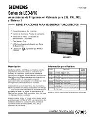
General Guidelines • Locate the sensing element in the downstream side of the coil.<br />
Large walk-in Ducts<br />
(Figure 1)<br />
• Locate the case and bellows where the ambient temperature is always warmer than<br />
the setpoint.<br />
• Install the thermostat so that the reset button is readily accessible and the element<br />
bellows points down.<br />
• Install as much of the bulb as possible in a horizontal plane. If too much of the bulb is<br />
vertical, it will not operate properly.<br />
• Avoid sharp bends or kinks in the sensing element.<br />
1. Attach the mounting bracket to the thermostat with the two round head screws<br />
provided.<br />
2. Mount the two perforated steel strap hangers inside the duct with the wide part of the<br />
hanger strap parallel to the air flow.<br />
3. Drill a hole in the side of the duct. With the bulb still coiled, thread the bulb through<br />
the hole using a rotary movement.<br />
4. Mount the thermostat on the outside of the duct.<br />
5. Carefully uncoil the bulb avoiding sharp bends or kinks in the sensing element.<br />
6. Mount the bulb in a horizontal, serpentine manner, attaching the bulb to the strap as<br />
shown in detail in Figure 1.<br />
The installation is complete.<br />
NOTE:<br />
For an alternate method of mounting, use coil clips (Part Number 356-115) in<br />
the fins to hold the bulb in a horizontal, serpentine pattern.<br />
<strong>Siemens</strong> Industry, Inc. Page 3
Technical Instructions<br />
Document Number 155-016P25<br />
September 14, 2005<br />
Low Temperature Detection Cut-out and Alarm Thermostat<br />
Mounting and<br />
Installation, Continued<br />
Figure 1. Typical Mounting in Walk-in Duct.<br />
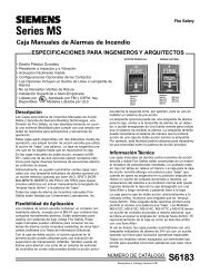
Limited Access Ducts<br />
(Figure 2)<br />
1. Attach the mounting bracket to the thermostat with the two round head screws<br />
provided.<br />
2. Attach a mounting flange (Part Number 808-412) on the opposite side of the duct<br />
(near the bottom) from where the thermostat will be mounted.<br />
3. Mount a second flange on an 8-inch by 4-inch sheet metal plate. Cut an access<br />
opening for the bulb on the duct diagonally across from the duct-mounted flange.<br />
Drill mounting screw holes for the sheet metal plate.<br />
4. Cut a length of copper tubing to fit diagonally across the duct. Stretch out the<br />
bulb and wrap it around the tubing. See Figure 2.<br />
5. Insert the tubing and bulb through the access hole and into the duct-mounted<br />
flange. Fasten the 8-inch by 4-inch sheet metal plate to the duct.<br />
6. Mount the thermostat on the outside of duct.<br />
Page 4<br />
<strong>Siemens</strong> Industry, Inc.
Low Temperature Detection Cut-out and Alarm Thermostat<br />
Technical Instructions<br />
Document Number 155-016P25<br />
September 14, 2005<br />
Figure 2. Bulb Mounting for Limited Access Ducts with 808-412 Mounting Flange.<br />
Wiring<br />
WARNING:<br />
Disconnect the power supply before wiring connections are made to<br />
avoid possible electrical shock or damage to the equipment.<br />
Make all wiring connections using copper conductors only and in accordance with the<br />
National Electrical Code and local regulations. Loads exceeding the rating of the<br />
thermostat should be handled by means of a relay or motor starter.<br />
An opening for 1/2-inch conduit is provided in the bottom of the thermostat enclosure.<br />
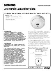
See Figure 3 for a typical wiring diagram.<br />
CAUTION:<br />
Figure 3. Typical Wiring Diagram.<br />
Use terminal screws furnished (#8-32 × 1/4-inch binder head screw).<br />
Longer terminal screws can interfere with switch mechanism and<br />
damage the switch.<br />
<strong>Siemens</strong> Industry, Inc. Page 5
Technical Instructions<br />
Document Number 155-016P25<br />
September 14, 2005<br />
Low Temperature Detection Cut-out and Alarm Thermostat<br />
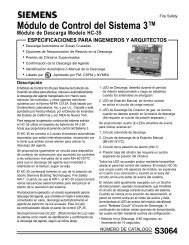
Adjustment<br />
After mounting the thermostat, adjust the temperature setting using the setpoint<br />
adjusting screw on the top of the enclosure. See Figure 4.<br />
Observe a complete operating cycle to be sure that all components function correctly.<br />
Figure 4. Setpoint Adjustment Screw.<br />
Calibration<br />
Troubleshooting<br />
Service<br />
There is no field calibration required for the thermostat.<br />
Observe a complete operating cycle to be sure that all components function correctly.<br />
There is no servicing of the thermostat. Replace if inoperative.<br />
Dimensions<br />
Figure 5. Dimensions in Inches (Millimeters).<br />
Information in this publication is based on current specifications. The company reserves the right to make changes in specifications and models as<br />
design improvements are introduced. Powers is a registered trademark of <strong>Siemens</strong> Industry, Inc. Product or company names mentioned herein<br />
may be the trademarks of their respective owners. © 2005 <strong>Siemens</strong> Industry, Inc.<br />
<strong>Siemens</strong> Industry, Inc.<br />
<strong>Building</strong> <strong>Technologies</strong> Division<br />
1000 Deerfield Parkway<br />
Buffalo Grove, IL 60089<br />
+ 1 847-215-1000<br />
Your feedback is important to us. If you have<br />
comments about this document, please send them<br />
to SBT_technical.editor.us.sbt@siemens.com<br />
Document No. 155-016P25<br />
Printed in the USA<br />
Page 6