

307889K ULTRA 500 AIRLESS PAINT SPRAYER - Graco Inc.
307889K ULTRA 500 AIRLESS PAINT SPRAYER - Graco Inc.
307889K ULTRA 500 AIRLESS PAINT SPRAYER - Graco Inc.

You also want an ePaper? Increase the reach of your titles
YUMPU automatically turns print PDFs into web optimized ePapers that Google loves.
INSTRUCTIONS–PARTS LIST 307–889<br />
This manual contains important<br />
warnings and information.<br />
READ AND RETAIN FOR REFERENCE<br />
Rev K<br />
Supercedes Rev J, never released,<br />
and Rev H<br />
220/240 VAC<br />
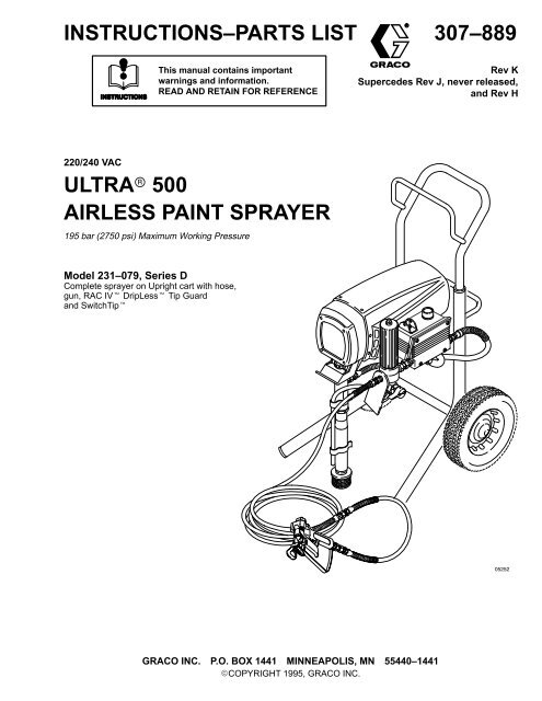
<strong>ULTRA</strong> <strong>500</strong><br />
<strong>AIRLESS</strong> <strong>PAINT</strong> <strong>SPRAYER</strong><br />
195 bar (2750 psi) Maximum Working Pressure<br />
Model 231–079, Series D<br />
Complete sprayer on Upright cart with hose,<br />
gun, RAC IV DripLess Tip Guard<br />
and SwitchTip<br />
<br />
GRACO INC. P.O. BOX 1441 MINNEAPOLIS, MN 55440–1441<br />
COPYRIGHT 1995, GRACO INC.
Warnings . . . . . . . . . . . . . . . . . . . . . . . . . . . . . . . . . . . . . . 2<br />
Setup . . . . . . . . . . . . . . . . . . . . . . . . . . . . . . . . . . . . . . . . . 6<br />
Startup . . . . . . . . . . . . . . . . . . . . . . . . . . . . . . . . . . . . . . . . 8<br />
Shutdown and Care . . . . . . . . . . . . . . . . . . . . . . . . . . . 10<br />
Flushing . . . . . . . . . . . . . . . . . . . . . . . . . . . . . . . . . . . . . 11<br />
Troubleshooting . . . . . . . . . . . . . . . . . . . . . . . . . . . . . . . 12<br />
Spin Test . . . . . . . . . . . . . . . . . . . . . . . . . . . . . . . . . . . . . 16<br />
General Repair Information . . . . . . . . . . . . . . . . . . . . . 18<br />
Motor Brush Replacement . . . . . . . . . . . . . . . . . . . . . 19<br />
Power Supply Cord Replacement . . . . . . . . . . . . . . . 20<br />
On/Off Switch Replacement . . . . . . . . . . . . . . . . . . . . 21<br />
Pressure Control Replacement . . . . . . . . . . . . . . . . . 22<br />
Filter Board Replacement . . . . . . . . . . . . . . . . . . . . . . 23<br />
Drive Housing, Connecting Rod, and Crankshaft<br />
Replacement . . . . . . . . . . . . . . . . . . . . . . . . . . . . . . . . . 24<br />
Table of Contents<br />
Symbols<br />
Motor Replacement . . . . . . . . . . . . . . . . . . . . . . . . . . . . 26<br />
Displacement Pump Repair . . . . . . . . . . . . . . . . . . . . . 28<br />
Parts Drawing – Upright Sprayer . . . . . . . . . . . . . . . . 31<br />
Parts List – Upright Sprayer . . . . . . . . . . . . . . . . . . . . 32<br />
Parts Drawing and List – Displacement Pump . . . . . 33<br />
Parts Drawing – Pressure Control . . . . . . . . . . . . . . . 34<br />
Parts List – Pressure Control . . . . . . . . . . . . . . . . . . . 34<br />
Wiring Diagram . . . . . . . . . . . . . . . . . . . . . . . . . . . . . . . 35<br />
Accessories . . . . . . . . . . . . . . . . . . . . . . . . . . . . . . . . . . 35<br />
Technical Data . . . . . . . . . . . . . . . . . . . . . . . . . . . . . . . . 36<br />
Dimensions . . . . . . . . . . . . . . . . . . . . . . . . . . . . . . . . . . . 36<br />
<strong>Graco</strong> Phone Numbers . . . . . . . . . . . . . . . . . . . . . . . . . 36<br />
The <strong>Graco</strong> Warranty and Disclaimers . . . . . . . . . . . . 36<br />
Warning Symbol<br />
WARNING<br />
his symbol alerts you to the possibility of serious<br />
injury or death if you do not follow the instructions.<br />
Caution Symbol<br />
CAUTION<br />
This symbol alerts you to the possibility of damage to<br />
or destruction of equipment if you do not follow the<br />
instructions.<br />
FIRE AND EXPLOSION HAZARD<br />
WARNING<br />
Improper grounding, poor ventilation, open flames or sparks can cause a hazardous condition and<br />
result in a fire or explosion and serious injury.<br />
<br />
<br />
<br />
<br />
<br />
<br />
<br />
<br />
If there is any static sparking or you feel an electric shock while using this equipment, stop<br />
spraying immediately. Do not use the equipment until you identify and correct the problem.<br />
Provide fresh air ventilation to avoid the buildup of flammable fumes from solvents or the fluid<br />
being sprayed.<br />
Keep the spray area free of debris, including solvent, rags, and gasoline.<br />
Electrically disconnect all equipment in the spray area.<br />
Extinguish all open flames or pilot lights in the spray area.<br />
Do not smoke in the spray area.<br />
Do not turn on or off any light switch in the spray area while operating or if fumes are present.<br />
Do not operate a gasoline engine in the spray area.
EQUIPMENT MISUSE HAZARD<br />
WARNING<br />
INSTRUCTIONS<br />
Equipment misuse can cause the equipment to rupture or malfunction and result in serious injury.<br />
<br />
This equipment is for professional use only.<br />
<br />
<br />
<br />
<br />
<br />
<br />
<br />
<br />
<br />
<br />
<br />
<br />
Read all instruction manuals, tags, and labels before operating the equipment.<br />
Use the equipment only for its intended purpose. If you are not sure, call <strong>Graco</strong> Technical Assistance<br />
at 1–800–543–0339.<br />
Do not alter or modify this equipment.<br />
Check equipment daily. Repair or replace worn or damaged parts immediately.<br />
Do not exceed the maximum working pressure of the lowest rated system component. Refer to<br />
the Technical Data on page 36 for the maximum working pressure of this equipment.<br />
Use fluids and solvents which are compatible with the equipment wetted parts. Refer to the Technical<br />
Data section of all equipment manuals. Read the fluid and solvent manufacturer’s warnings.<br />
Do not use 1,1,1–trichloroethane, methylene chloride, other halogenated hydrocarbon solvents or<br />
fluids containing such solvents in pressurized aluminum equipment. Such use could result in a<br />
chemical reaction, with the possibility of explosion.<br />
Do not use hoses to pull equipment.<br />
Route hoses away from traffic areas, sharp edges, moving parts, and hot surfaces. Do not expose<br />
<strong>Graco</strong> hoses to temperatures above 82C (180F) or below –40C (–40F).<br />
Do not lift pressurized equipment.<br />
Comply with all applicable local, state, and national fire, electrical, and safety regulations.<br />
Wear hearing protection when operating this equipment.<br />
TOXIC FLUID HAZARD<br />
Hazardous fluid or toxic fumes can cause serious injury or death if splashed in the eyes or on the<br />
skin, inhaled, or swallowed.<br />
<br />
<br />
<br />
Know the specific hazards of the fluid you are using.<br />
Store hazardous fluid in an approved container. Dispose of hazardous fluid according to all local,<br />
state and national guidelines.<br />
Always wear protective eyewear, gloves, clothing and respirator as recommended by the fluid<br />
and solvent manufacturer.<br />
MOVING PARTS HAZARD<br />
Moving parts, such as the air motor piston, can pinch or amputate your fingers.<br />
<br />
<br />
Keep clear of all moving parts when starting or operating the pump.<br />
Before servicing the equipment, follow the Pressure Relief Procedure on page 12 to prevent the<br />
equipment from starting unexpectedly.
INJECTION HAZARD<br />
WARNING<br />
Spray from the gun, leaks or ruptured components can inject fluid into your body and cause extremely<br />
serious injury, including the need for amputation. Fluid splashed in the eyes or on the skin<br />
can also cause serious injury.<br />
<br />
<br />
<br />
<br />
<br />
<br />
<br />
<br />
<br />
<br />
<br />
<br />
<br />
Fluid injected into the skin is a serious injury. The injury may look like just a cut, but it is a serious<br />
injury. Get immediate medical attention.<br />
Do not point the gun at anyone or at any part of the body.<br />
Do not put your hand or fingers over the spray tip.<br />
Do not stop or deflect leaks with your hand, body, glove or rag.<br />
Do not “blow back” fluid; this is not an air spray system.<br />
Always have the tip guard and the trigger guard on the gun when spraying.<br />
Check the gun diffuser operation weekly. Refer to the gun manual.<br />
Be sure the gun trigger safety operates before spraying.<br />
Lock the gun trigger safety when you stop spraying.<br />
Follow the Pressure Relief Procedure on page 12 if the spray tip clogs and before cleaning,<br />
checking or servicing the equipment.<br />
Tighten all fluid connections before operating the equipment.<br />
Check the hoses, tubes, and couplings daily. Replace worn or damaged parts immediately. Do<br />
not repair high pressure couplings; you must replace the entire hose.<br />
Fluid hoses must have spring guards on both ends, to help protect them from rupture caused by<br />
kinks or bends near the couplings.<br />
NOTE: This is an example of the DANGER label on your sprayer. This label is available in other languages,<br />
free of charge. See page 35 to order.<br />
FIRE AND<br />
EXPLOSION HAZARD<br />
SKIN INJECTION<br />
HAZARD<br />
Spray painting, flushing or cleaning equipment with flammable liquids<br />
in confined areas can result in fire or explosion.<br />
Use outdoors or in extremely well ventilated areas. Ground equipment,<br />
hoses, containers and objects being sprayed.<br />
Avoid all ignition sources such as static electricity from plastic drop<br />
cloths, open flames such as pilot lights, hot objects such as cigarettes,<br />
arcs from connecting or disconnecting power cords or turning<br />
light switches on and off.<br />
Failure to follow this warning can result in death or serious injury.<br />
Liquids can be injected into the body by high pressure airless spray<br />
or leaks – especially hose leaks.<br />
Keep body clear of the nozzle. Never stop leaks with any part of the<br />
body. Drain all pressure before removing parts.Avoid accidental triggering<br />
of gun by always setting safety latch when not spraying.<br />
Never spray without a tip guard.<br />
In case of accidental skin injection, seek immediate<br />
“Surgical Treatment”.<br />
Failure to follow this warning can result in amputation or serious<br />
injury.<br />
READ AND UNDERSTAND ALL LABELS AND INSTRUCTION MANUALS BEFORE USE
Major Components<br />
T<br />
M<br />
K<br />
C<br />
B<br />
A<br />
D<br />
<br />
E<br />
H<br />
S<br />
R<br />
P<br />
J<br />
N<br />
Fig. 1<br />
L<br />
<br />
A Motor DC motor, 220/240 Vac, 50 Hz, 7A, 1 phase<br />
B Pressure Adjusting Knob Controls fluid outlet pressure<br />
C ON/OFF Switch Power switch that controls 220/240 Vac main power to sprayer<br />
D Drive Assembly Transfers power from DC motor to the displacement pump<br />
E Fluid Filter Final filter of fluid between source and spray gun<br />
H Displacement Pump Transfers fluid to be sprayed from source through spray gun<br />
J 50 ft (15 m) Main Hose 1/4 in. ID, grounded, nylon hose with spring guards on both ends<br />
K RAC IV Tip Guard Reverse-A-Clean (RAC) tip guard reduces risk of injection injury<br />
L Contractor Gun High pressure spray gun with gun safety latch<br />
M RAC IV Switch Tip RAC switch tip uses high pressure fluid to remove clogs from spray<br />
tip without removing tip from spray gun<br />
N 3 ft (0.9 m) Hose 3/16 in. ID, grounded, nylon hose used between 50 ft hose and<br />
spray gun to allow more flexibility when spraying<br />
P Primary Fluid Outlet Single spray gun operation is connected here<br />
R Pressure Drain Valve Relieves fluid outlet pressure when open<br />
S Pressure Control Controls motor speed to maintain fluid outlet pressure at displacement<br />
pump oulet. Works with pressure adjusting knob.<br />
T Spray Gun Safety Latch Gun safety latch inhibits accidental triggering of spray gun
Setup<br />
WARNING<br />
To reduce the risk of serious injury from static<br />
sparking, injection, or over pressurization and<br />
rupture of the hose or gun, all hoses must be electrically<br />
conductive, the gun must have a tip guard, and<br />
each part must be rated for at least 210 bar (3000 psi)<br />
Maximum Working Pressure.<br />
CAUTION<br />
To avoid damaging the pressure control, which may<br />
result in poor equipment performance and component<br />
damage, follow these precautions:<br />
1. Always use grounded, flexible spray hose at<br />
least 50 ft. (15 m) long.<br />
2. Never use a wire braid hose as it is too rigid to act<br />
as a pulsation dampener.<br />
3. Never install any shutoff device between the filter<br />
and the main hose. See Fig. 2.<br />
4. Always use the main filter outlet for one gun operation.<br />
Never plug this outlet.<br />
WARNING<br />
FIRE AND EXPLOSION HAZARD<br />
Proper electrical grounding is essential<br />
to reduce the risk of fire or explosion<br />
which can result in serious injury and<br />
property damage. Read the warning section<br />
FIRE OR EXPLOSION HAZARD on<br />
page 2 for more detailed grounding<br />
instructions.<br />
NOTE: See Fig. 2 while doing the setup.<br />
1. Fill the packing nut/wet-cup 1/3 full with <strong>Graco</strong><br />
Throat Seal Liquid (TSL), supplied.<br />
2. Connect the gun, 0.9 m (3 ft) hose and 15.1 m<br />
(50 ft) hose. Screw the assembly onto the outlet<br />
nipple. Don’t use thread sealant and don’t install<br />
the spray tip yet!<br />
3. Check the Electrical Service.<br />
a. Electrical requirements: 220/240 V AC, 50 Hz,<br />
7A (minimum).<br />
b. Use a grounded electrical outlet located at least<br />
6 m (20 ft) from the spray area.<br />
b. Do not remove the grounding prong of the power<br />
supply cord and do not use an adapter.<br />
c. Extension cord specifications: 10A, 3-wire,<br />
grounding type. (Long lengths reduce sprayer<br />
performance.)<br />
4. Plug in the sprayer. Turn the ON/OFF switch<br />
OFF. Plug the cord into a grounded electrical outlet.<br />
5. Flush the pump to remove the oil left in to protect<br />
pump parts after factory testing. See Flushing<br />
on page 11.<br />
6. Prepare the paint according to the manufacturer’s<br />
recommendations. Remove any paint skin. Stir the<br />
paint thoroughly. Strain the paint through a fine<br />
nylon mesh bag (available at most paint dealers)<br />
to remove particles that could clog the filter or<br />
spray tip. This is an important step for trouble-free<br />
paint spraying.
Setup<br />
PRESSURE ADJUSTING KNOB<br />
ON/OFF SWITCH<br />
PACKING NUT/ WET–CUP<br />
FILL 1/3 FULL WITH TSL<br />
PRESSURE<br />
DRAIN<br />
VALVE<br />
1/4 npsm(m) FLUID OUTLET NIPPLE<br />
DO NOT INSTALL ANY SHUTOFF<br />
DEVICE HERE<br />
Fig. 2
Startup<br />
Use this procedure each time you start the sprayer to<br />
help ensure the sprayer is ready to operate and that you<br />
start it safely.<br />
WARNING<br />
INJECTION HAZARD<br />
To reduce the risk of serious injury,<br />
follow the illustrated Pressure Relief<br />
Procedure warning on page 12 whenever<br />
you are instructed to relieve pressure.<br />
NOTE: Flush the sprayer if this is a first-time startup.<br />
See page 11.<br />
NOTE: See Fig. 4 except where noted.<br />
1. Put the suction tube into the paint container.<br />
2. Turn the pressure adjusting knob fully counterclockwise<br />
to zero pressure.<br />
3. Plug in the sprayer.<br />
CAUTION<br />
c. Release the trigger. Engage the gun safety latch.<br />
5. Check all fluid connections for leaks. Relieve<br />
the fluid pressure before tightening connections.<br />
6. Install the spray tip and tip guard. Engage the<br />
gun safety latch. See Fig. 3. Install the spray tip<br />
according to the instructions supplied with it.<br />
7. Adjust the spray pattern.<br />
a. <strong>Inc</strong>rease the pressure just until spray from the<br />
gun is completely atomized. Use the lowest<br />
pressure needed to get the desired results. This<br />
reduces overspray and fogging, decreases tip<br />
wear and extends the life of the sprayer.<br />
b. If more coverage is needed, use a larger tip<br />
rather than increasing the pressure.<br />
c. Test the spray pattern. T o adjust the pattern,<br />
engage the gun safety latch, loosen the retaining<br />
nut. Position the tip guard horizontally for a horizontal<br />
pattern or vertically for a vertical pattern.<br />
Then tighten the retaining nut.<br />
GUN SAFETY<br />
LATCH SHOWN<br />
ENGAGED<br />
Do not run the pump without fluid in it for more than<br />
30 seconds to avoid damage to the displacement<br />
pump packings.<br />
WARNING<br />
FIRE AND EXPLOSION HAZARD<br />
To reduce the risk of static sparking and<br />
splashing when flushing, always remove<br />
the spray tip from the gun and hold a<br />
metal part of the gun firmly to the side of a<br />
grounded metal pail.<br />
Fig. 3<br />
ON/OFF SWITCH<br />
GUN SAFETY LATCH<br />
SHOWN DISENGAGED<br />
01020A<br />
PRESSURE<br />
ADJUSTING<br />
KNOB<br />
4. Prime the pump.<br />
a. Open the pressure drain valve (handle in downward<br />
position). Turn the ON/OFF switch to ON.<br />
Slowly turn the pressure adjusting knob clockwise<br />
until the sprayer starts. When fluid comes<br />
from the drain hose, close the valve (handle in<br />
forward position).<br />
b. Disengage the gun safety latch. See Fig. 3.<br />
Following the warning, above, trigger the gun<br />
until all air is forced out of the system and the<br />
paint flows freely from the gun.<br />
DRAIN<br />
HOSE<br />
Fig. 4<br />
OUTLET<br />
NIPPLE<br />
PRESSURE<br />
DRAIN<br />
VALVE
Startup<br />
Cleaning a Clogged Tip<br />
WARNING<br />
FLUID INJECTION HAZARD<br />
To reduce the risk of serious injury,<br />
follow the illustrated Pressure Relief<br />
Procedure warning on page 12 whenever<br />
you are instructed to relieve pressure.<br />
1. Clean the front of the tip frequently during the day’s<br />
operation. First, relieve pressure.<br />
2. If the spray tip does clog, release the gun trigger, engage<br />
the gun safety latch, and rotate the RAC IV<br />
handle 180. See Fig. 5.<br />
4. Return the handle to the original position, disengage<br />
the gun safety latch, and resume spraying.<br />
5. If the tip is still clogged, engage the gun safety latch,<br />
shut off and unplug the sprayer, and open the pressure<br />
drain valve to relieve pressure. Clean the spray<br />
tip as shown on the RAC IV package.<br />
TIP GUARD HANDLE<br />
SHOWN IN SPRAYING<br />
POSITION<br />
TURN HANDLE 180,<br />
DISENGAGE SAFETY<br />
LATCH AND TRIGGER<br />
GUN TO CLEAR CLOG<br />
GUN SAFETY<br />
LATCH<br />
SHOWN<br />
ENGAGED<br />
3. Disengage the gun safety latch and trigger the gun<br />
into a waste container. Engage the gun safety latch<br />
again.<br />
Fig. 5
Shutdown and Care<br />
WARNING<br />
FLUID INJECTION HAZARD<br />
To reduce the risk of serious injury,<br />
follow the illustrated Pressure Relief<br />
Procedure warning on page 12 whenever<br />
you are instructed to relieve pressure.<br />
6. Coil the hose and hang it on the hose rack when<br />
storing it, even for overnight, to help protect the hose<br />
from kinking, abrasion, coupling damage, etc.<br />
1. Check the packing nut/wet-cup daily. First relieve<br />
pressure. Keep the wet-cup 1/3 full of TSL at all times<br />
to help prevent fluid buildup on the piston rod and<br />
premature wear of packings.<br />
PACKING NUT/<br />
WET–CUP<br />
Tighten the packing nut just enough to stop leakage.<br />
Over tightening causes binding and excessive packing<br />
wear. Use a round punch or brass rod and light<br />
hammer to adjust the nut. Refer to Fig. 6.<br />
2. Clean the fluid filter often and whenever the sprayer<br />
is stored. Follow the Flushing Guidelines on page<br />
11 or refer to manual 307–273, supplied, for the<br />
cleaning procedure.<br />
3. Lubricate the bearing housing after every 100<br />
hours of operation. First relieve pressure. Remove<br />
the front cover. Fill the bearing housing cavity with<br />
SAE 10 non-detergent oil. See Fig. 7.<br />
4. For very short shutoff periods, leave the suction<br />
tube in the paint, relieve pressure, and clean the<br />
spray tip.<br />
5. Flush the sprayer at the end of each work day and<br />
fill it with mineral spirits to help prevent pump corrosion<br />
and freezing. See page 11.<br />
TIGHTEN<br />
Fig. 6<br />
FILL BEARING HOUSING<br />
CAVITY WITH SAE 10<br />
NON-DETERGENT OIL<br />
AFTER EVERY 100<br />
HOURS OF OPERATION<br />
FRONT<br />
COVER<br />
<br />
CAUTION<br />
To prevent pump corrosion, never leave water or any<br />
type of paint in the sprayer when it is not in use. Pump<br />
water or paint out with mineral spirits.<br />
Fig. 7
Flushing<br />
NOTE: Several flushes are often required to thoroughly clean the system and prepare it for the next fluid to be<br />
sprayed, or to store the sprayer. Use this chart to determine the required flushing order for the fluid you are<br />
using, and then follow the procedure below for flushing.<br />
*Use this category for flushing a brand new sprayer and flushing after storage.<br />
System has<br />
this fluid in it:<br />
*Oil-based<br />
solvent or paint<br />
Oil-based<br />
solvent or paint<br />
Oil-based<br />
solvent or paint<br />
Water or waterbased<br />
paint<br />
Water or waterbased<br />
paint<br />
Water or waterbased<br />
paint<br />
Next fluid to be<br />
sprayed.<br />
Oil-based paint –<br />
new color<br />
Flushing order:<br />
Flush 1 Flush 2 Flush 3<br />
Before you spray or store<br />
sprayer:<br />
Mineral spirits none none Prime with oil-based paint<br />
Water-based paint Mineral spirits Warm soapy<br />
water<br />
Prepare for<br />
storage<br />
Water-based paint<br />
– new color<br />
Oil-based paint<br />
Prepare for<br />
storage<br />
Clean water<br />
Prime with water-based<br />
paint<br />
Mineral spirits none none Relieve pressure,<br />
Leave drain valve open<br />
Warm soapy<br />
water<br />
Warm soapy<br />
water<br />
Warm soapy<br />
water<br />
Clean water none Prime with water<br />
Clean water Mineral spirits Prime with oil<br />
Clean water Mineral spirits Relieve pressure,<br />
Leave drain valve open<br />
WARNING<br />
FIRE AND EXPLOSION HAZARD<br />
To reduce the risk of static sparking and<br />
splashing when flushing, always remove<br />
the spray tip from the gun and hold a<br />
metal part of the gun firmly to the side of a<br />
grounded metal pail.<br />
1. Follow the illustrated Pressure Relief Procedure<br />
on page 12. Engage the gun safety latch.<br />
6. Do not run the pump dry for more than 30 seconds<br />
to avoid damaging the pump packings!<br />
7. Follow the illustrated Pressure Relief Procedure<br />
on page 12. Engage the gun safety latch.<br />
8. Unscrew the filter bowl and reinstall the clean<br />
screen. Install the bowl and hand tighten.<br />
9. Remove the suction tube and screen and clean<br />
them separately.<br />
2. Turn the pressure adjusting knob fully counterclockwise<br />
to zero pressure.<br />
3. Remove the spray tip from the gun. Remove the<br />
filter bowl and screen; see manual 307–273. Clean<br />
the screen separately and install the bowl without<br />
the screen to flush it. See Fig. 8.<br />
4. Put the suction tube into a grounded metal pail<br />
with 1/2 gallon of compatible solvent.<br />
SCREEN<br />
FILTER<br />
SUPPORT<br />
FILTER<br />
BOWL<br />
5. Start the sprayer. See page 8. To save the fluid<br />
still in the sprayer, trigger the gun into another<br />
container until the next fluid appears, then trigger<br />
the gun back into the fluid you are pumping. Circulate<br />
the flushing fluid a couple of minutes to thoroughly<br />
clean the system.<br />
Fig. 8<br />
PRESSURE<br />
DRAIN VALVE
Troubleshooting<br />
Pressure Relief Procedure<br />
To reduce the risk of serious bodily injury, including fluid injection,<br />
splashing fluid or solvent in the eyes or on the skin,<br />
or injury from moving parts or electric shock, always follow<br />
this procedure whenever you shut of f the sprayer , when<br />
checking or servicing any part of the spray system, when installing,<br />
cleaning or changing spray tips, and whenever you<br />
stop spraying.<br />
1. Engage the gun safety latch.<br />
2. Turn the ON/OFF switch to OFF.<br />
3. Unplug the power supply cord.<br />
4. Disengage the gun safety latch. Hold a metal part of the<br />
gun firmly to the side of a grounded metal pail, and trigger<br />
the gun to relieve pressure.<br />
5. Engage the gun safety latch.<br />
6. Open the pressure drain valve, having a container<br />
ready to catch the drainage. Leave the valve open until<br />
you are ready to spray again.<br />
If you suspect that the spray tip or hose is completely<br />
clogged, or that pressure has not been fully relieved after following<br />
the steps above, VERY SLOWLY loosen the tip guard<br />
retaining nut or hose coupling to relieve pressure gradually,<br />
then loosen completely. Now clear the tip or hose.<br />
<br />
6<br />
<br />
Perform all Troubleshooting procedures before disassembling the sprayer.<br />
MOTOR WON’T OPERATE<br />
TYPE OF PROBLEM<br />
Basic Fluid Pressure Problems<br />
WHAT TO CHECK<br />
If check is OK, go to next check<br />
1. Check the pressure control knob setting. The<br />
motor will not run if it is at the minimum setting<br />
(fully counterclockwise).<br />
WHAT TO DO<br />
When check is not OK refer to this column<br />
1. Slowly increase the pressure setting to see<br />
if the motor starts.<br />
Basic Mechanical Problems<br />
2. Check for a clogged spray tip or fluid filter. Refer<br />
to the separate gun, tip, or fluid filter instruction<br />
manual.<br />
1. Check for frozen or hardened paint in the<br />
pump (19) and/or pressure control tube. Using<br />
a screwdriver, carefully try to rotate fan at back<br />
of motor by hand. See page 16.<br />
2. Check displacement pump connecting rod pin<br />
(20). It must be completely pushed into connecting<br />
rod (9) and retaining spring (21) must<br />
be firmly in groove of connecting rod. See Fig.<br />
32.<br />
3. Check for motor damage. Remove drive<br />
housing assembly (6). See page 24. Try to rotate<br />
fan by hand.<br />
2. Relieve pressure, refer to the separate gun,<br />
tip, or fluid filter instruction manual for<br />
cleaning.<br />
1. Thaw. Plug in sprayer and turn on. Slowly<br />
increase pressure setting to see if motor<br />
starts. If it doesn’t, see NOTE 1, below.<br />
2. Push pin into place and secure with spring<br />
retainer.<br />
3. Replace motor (2) if fan won’t turn. See<br />
page 26.<br />
Basic Electrical Problems 1. Check pressure control safety circuit. 2. Turn pressure control ON/OFF switch to<br />
OFF to RESET. If the pressure control safety<br />
continues to trip, see ELECTRICAL<br />
SHORT on page 16.<br />
2. Check electrical supply with volt meter. Meter<br />
should read 200–250 VAC.<br />
3. Check extension cord fordamage. Check extension<br />
cord continuity with a volt meter.<br />
4. Check sprayer power supply cord (314) for<br />
damage such as broken insulation or wires.<br />
5. Check motor brush leads, terminals and brush<br />
length. Brush length should be 1/2” (12 mm)<br />
minimum. See page 19.<br />
2. Reset building circuit breaker; replace<br />
building fuse. Try another outlet.<br />
3. Replace extension cord.<br />
4. Replace power supply cord. See page 20.<br />
5. Tighten terminal screws; replace brushes.<br />
See page 19.<br />
NOTE 1: Thaw the sprayer if water or water-based paint has frozen in it, due to exposure to low temperatures, by placing it in a warm<br />
area. Do not try to start the sprayer until it has thawed completely. If paint hardened (dried) in the sprayer, the pump packings and/or<br />
pressure control must be replaced. See page 28 (Displacement Pump) or 22 (Pressure Control).
MOTOR WON’T OPERATE (Continued)<br />
TYPE OF PROBLEM<br />
Follow Pressure Relief Procedure<br />
on page 13. Remove gun<br />
from hose. Remove pressure<br />
control.<br />
Refer to the wiring diagram<br />
on page 35 to identify test<br />
points (TP).<br />
WHAT TO CHECK<br />
If check is OK, go to next check<br />
1. Check leads from motor to be sure they are<br />
securely fastened and properly mated.<br />
2. Check for loose motor brush lead connections<br />
and terminals. See page 19.<br />
3. Check brush length which should be 12 mm<br />
(1/2 in.) minimum. See page 19.<br />
NOTE: The brushes do not wear at the same<br />
rate on both sides of the motor . Check both<br />
brushes.<br />
4. Check for broken or misaligned motor brush<br />
springs. Rolled portion of spring must rest<br />
squarely on top of brush. See page 19.<br />
5. Check motor brushes for binding in brush<br />
holders. See page 19.<br />
6. Check motor armature commutator for burn<br />
spots, gouges and extreme roughness. Remove<br />
motor cover and brush inspection<br />
plates to check. See page 19.<br />
7. Check motor armature for shorts using armature<br />
tester (growler) or perform spin test. See<br />
page 16.<br />
8. Check pressure control board (301) by substituting<br />
with a good pressure control board. See<br />
page 22.<br />
9. Check filter board. Connect volt meter to TP7<br />
and ON/Off switch TP3.Connect a jumper<br />
from TP4 to TP8. Plug in sprayer . Meter<br />
should read 200 to 250 VAC. Unplug sprayer.<br />
Remove jumper.<br />
1. Check power supply cord (314). Disconnect<br />
TP1 female (neutral) and TP2 female and<br />
connect volt meter to these leads. Plug in<br />
sprayer. Meter should read 200 to 250 V AC.<br />
Unplug sprayer. Reconnect TP2.<br />
2. Check ON/OFF switch (307). Disconnect TP3<br />
and TP4 and connect volt meter to TP3 and<br />
TP4 terminal on the ON/OFF switch. Plug in<br />
sprayer and turn ON. Meter should read 200<br />
to 250 VAC. Turn off and unplug sprayer. Reconnect<br />
TP3.<br />
3. Check motor terminal cutoff switch. Connect<br />
volt meter to TP1 female and TP6 female.<br />
Plug in sprayer and turn on. Meter should read<br />
200 to 250 VAC. Turn off and unplug sprayer.<br />
4. Check all terminals for damage or loose fit.<br />
Reconnect TP1, TP2, TP3, TP4, TP5, and<br />
TP6 connectors.<br />
WHAT TO DO<br />
When check is not OK refer to this column<br />
1. Replace loose terminals; crimp to leads. Be<br />
sure male terminal blades are straight and<br />
firmly connected to mating part.<br />
Clean circuit board male terminals. Replace<br />
loose or damaged terminals. Securely<br />
reconnect leads.<br />
2. Tighten terminal screws. Replace brushes<br />
if leads are damaged. See page 19.<br />
3. Replace brushes. See page 19.<br />
4. Replace spring if broken. Realign spring<br />
with brush. See page 19.<br />
5. Clean brush holders. Remove carbon with<br />
small cleaning brush. Align brush leads<br />
with slot in brush holder to assure free vertical<br />
brush movement.<br />
6. Remove motor and have motor shop resurface<br />
commutator if possible. See page 26.<br />
7. Replace motor. See page 26.<br />
8. Replace with new pressure control board<br />
(301). See page 22.<br />
9. Temporary bypass to check (Replace filter<br />
board?)<br />
1. Replace power supply cord. See page 20.<br />
2. Replace ON/OFF switch. See page 21.<br />
3. Allow motor to cool. Correct cause of overheating.<br />
If switch remains open after motor<br />
cools, check continuity between TP4 female<br />
and TP5 female with ohmmeter . If<br />
open, replace motor.<br />
4. Replace damaged terminals and reconnect<br />
securely.
LOW OUTPUT<br />
TYPE OF PROBLEM<br />
WHAT TO CHECK<br />
If check is OK, go to next check<br />
WHAT TO DO<br />
When check is not OK refer to this column<br />
Low Output 1. Check for worn spray tip. 1. Follow Pressure Relief Procedure Warning<br />
then replace tip. See your separate gun<br />
or tip manual.<br />
2. Check to see that pump does not continue to<br />
stroke when gun trigger is released. Plug in<br />
and turn on sprayer. Prime with paint. Trigger<br />
gun momentarily, then release and engage<br />
safety latch. Relieve pressure, turn off and unplug<br />
sprayer.<br />
3. Check electrical supply with volt meter. Meter<br />
should read 200–250 VAC.<br />
2. Service pump. See pages 28–30.<br />
3. Reset building circuit breaker; replace<br />
building fuse. Repair electrical outlet or try<br />
another outlet.<br />
4. Check extension cord size and length; must<br />
be at least 1.5 mm 2 (12 AWG) wire and no<br />
longer than 100m (300 ft).<br />
5. Check +, –, M+ and M– leads from motor to<br />
pressure control circuit board (B1) for damaged<br />
or loose wires or connectors. Inspect<br />
wiring insulation and terminals for signs of<br />
overheating. See page 26.<br />
6. Check for loose motor brush leads and terminals.<br />
See page 19.<br />
7. Check for worn motor brushes which should<br />
be 12 mm (1/2 in.) minimum. See page 19.<br />
8. Check for broken and misaligned motor brush<br />
springs. Rolled portion of spring must rest<br />
squarely on top of brush.<br />
9. Check motor brushes for binding in brush<br />
holders. See page 19.<br />
10.Check stall pressure. Gauge should read 170<br />
bar (2<strong>500</strong> psi) minimum.<br />
11. Check pressure control board (301) by substituting<br />
with a good pressure control board. See<br />
page 22.<br />
4. Replace with a correct, grounded extension<br />
cord.<br />
5. Be sure male terminal blades are centered<br />
and firmly connected to female terminals.<br />
Replace any loose terminal or damaged<br />
wiring. Securely reconnect terminals.<br />
6. Tighten terminal screws. Replace brushes<br />
if leads are damaged. See page 19.<br />
7. Replace brushes. See page 19.<br />
8. Replace spring if broken. Realign spring<br />
with brush. See page 19.<br />
9. Clean brush holders, remove carbon dust<br />
with small cleaning brush. Align brush lead<br />
with slot in brush holder to assure free vertical<br />
brush movement.<br />
10.Replace with new pressure control board<br />
(301). See page 22.<br />
11. Replace with new pressure control board<br />
(301). See page 22.<br />
12.Check motor armature for shorts by using an<br />
armature tester (growler) or perform spin test.<br />
See page 16.<br />
12.Replace motor. See page 26.
NO OUTPUT<br />
TYPE OF PROBLEM<br />
WHAT TO CHECK<br />
If check is OK, go to next check<br />
WHAT TO DO<br />
When check is not OK refer to this column<br />
Motor runs and pump strokes 1. Check paint supply. 1. Refill and reprime pump.<br />
2. Check for clogged intake strainer. 2. Remove and clean, then reinstall.<br />
3. Check for loose suction tube or fittings. 3. Tighten; use thread sealant or sealing tape<br />
on threads if necessary.<br />
Motor runs but pump does not<br />
stroke<br />
4. Check to see if intake valve ball and piston ball<br />
are seating properly. See page 28.<br />
5. Check for leaking around throat packing nut<br />
which may indicate worn or damaged packings.<br />
See page 28.<br />
1. Check displacement pump connecting rod pin<br />
(20). See page 30.<br />
2. Check connecting rod assembly (68) for damage.<br />
See page 24.<br />
3. Be sure crank in drive housing rotates; plug in<br />
sprayer and turn on briefly to check. Turn off<br />
and unplug sprayer. See page 24.<br />
4. Remove intake valve and clean. Check<br />
balls and seats for nicks; replace if necessary.<br />
See page 28. Strain paint before using<br />
to remove particles that could clog the<br />
pump.<br />
5. Replace packings. See pages 28–33. Also<br />
check piston valve seat for hardened paint<br />
or nicks and replace if necessary. Tighten<br />
the packing nut/wet-cup.<br />
1. Replace pin if missing. Be sure retainer<br />
spring (42) is fully in groove all around connecting<br />
rod. See page 30.<br />
2. Replace connecting rod assembly . See<br />
page 24.<br />
3. Check drive housing assembly for damage<br />
and replace if necessary. See page 24.<br />
EXCESSIVE PRESSURE FLUCTUATIONS<br />
TYPE OF PROBLEM<br />
Spray pattern variations.<br />
WHAT TO CHECK<br />
If check is OK, go to next check<br />
1. Be sure leads to pressure control circuit board<br />
(B1) are firmly connected. Be sure all male terminals<br />
blades are centered and firmly connected<br />
to female terminals. See Fig. 33.<br />
WHAT TO DO<br />
When check is not OK refer to this column<br />
1. Reconnect securely. See Fig. 33.<br />
2. Check maximum working pressure. 2. Replace with a new pressure control board<br />
(301). See page 22.<br />
3. Check pressure control board (301) by substituting<br />
with a good pressure control board. See<br />
page 22.<br />
3. Replace with a new pressure control board<br />
(301). See page 22.<br />
4. Check LOW OUTPUT section, page 14.
MOTOR IS HOT AND RUNS INTERMITTENTLY<br />
TYPE OF PROBLEM<br />
Motor is hot and runs intermittently.<br />
ELECTRICAL SHORT<br />
WHAT TO CHECK<br />
If check is OK, go to next check<br />
1. Determine if sprayer was operated at high<br />
pressure with small tips, which causes low<br />
motor RPM and excessive heat build up.<br />
2. Be sure ambient temperature where sprayer<br />
is located is no more than 32C (90F) and<br />
sprayer is not located in direct sun.<br />
3. Determine if sprayer was turned on, pressurized,<br />
but not operating for long periods of time.<br />
WHAT TO DO<br />
When check is not OK refer to this column<br />
1. Decrease pressure setting or increase tip<br />
size.<br />
2. Move sprayer to shaded, cooler area if possible.<br />
3 Turn off sprayer whenever you stop spraying<br />
for a while and relieve fluid pressure.<br />
TYPE OF PROBLEM<br />
Building circuit breaker opens<br />
as soon as sprayer switch is<br />
turned on.<br />
CAUTION<br />
Any short in any part of the<br />
motor power circuit will cause<br />
the control circuit to inhibit<br />
sprayer operation. Correctly<br />
diagnose and repair all shorts<br />
before checking and replacing<br />
control board.<br />
Building circuit breaker opens<br />
as soon as sprayer is plugged<br />
into outlet and sprayer is NOT<br />
turned on.<br />
Sprayer quits after sprayer operates<br />
for 5 to 10 minutes.<br />
WHAT TO CHECK<br />
If check is OK, go to next check<br />
1. Check all electrical wiring for damaged insulation,<br />
and all terminals for loose fit or damage.<br />
Also check wires between pressure control<br />
and motor which are encased in conduit (1).<br />
See page 26.<br />
2. Check for missing inspection plate gasket<br />
(see page 26), bent terminal forks or other<br />
metal to metal contact points which could<br />
cause a short.<br />
3. Check motor armature for shorts. Use an armature<br />
tester (growler) or perform spin test.<br />
See page 16. Inspect windings for burns.<br />
4. Check pressure control board (301) by substituting<br />
with a good control board. See page 22.<br />
WHAT TO DO<br />
When check is not OK refer to this column<br />
1. Repair or replace any damaged wiring or<br />
terminals. Securely reconnect all wires.<br />
2. Correct faulty conditions.<br />
3. Replace motor. See page 26.<br />
4. Replace with a new pressure control board<br />
(301). See page 22.<br />
1. Check Basic Electrical Problems on page 12. 1. Perform necessary procedures.<br />
2. Check ON/OFF switch (307) See page 21. Be<br />
sure the sprayer is unplugged! Disconnect<br />
wires from switch. Check switch with ohmmeter.<br />
The reading should be infinity with the ON/<br />
OFF switch OFF, and zero with the switch ON.<br />
3. Check for damaged or pinched wires in the<br />
pressure control. See page 22.<br />
2. Replace ON/OFF switch. See page 21.<br />
3. Replace damaged parts. See page 22.<br />
1. Check Basic Electrical Problems on page 12. 1. Perform necessary procedures.<br />
2. Check electrical supply with volt meter. Meter<br />
should read 200 to 250 VAC.<br />
3. Check tightness of pump packing nut. Overtightening<br />
tightens packings on rod, restricts<br />
pump action, and damages packings.<br />
2. If voltage is too high, do not operate<br />
sprayer until corrected.<br />
3. Loosen packing nut. Check for leaking<br />
around throat. Replace pump packings, if<br />
necessary. See page 28.<br />
Spin Test<br />
WARNING<br />
ELECTRIC SHOCK HAZARD<br />
Do not touch the brushes, leads, springs<br />
or brush holders while the sprayer is<br />
plugged in to reduce the risk of electric<br />
shock and serious bodily injury.<br />
WARNING<br />
INJECTION HAZARD<br />
To reduce the risk of serious injury,<br />
follow the illustrated Pressure Relief<br />
Procedure warning on page 12 whenever<br />
you are instructed to relieve pressure.
For checking armature, motor winding and brush electrical<br />
continuity.<br />
Setup<br />
Relieve pressure. Remove the drive housing. See page<br />
24.<br />
Remove the motor shield (1), the fan cover (F) and the<br />
inspection covers (J). See Fig. 9.<br />
Remove the pressure control/cover(301). Disconnect<br />
the – and + leads from the motor to the pressure control/<br />
cover terminals M–, and M+. See Fig. 10.<br />
Armature Short Circuit Test<br />
Relieve pressure. Quickly turn the motor fan by hand. If<br />
there are no shorts, the motor will coast two or three revolutions<br />
before coming to a complete stop. If the motor<br />
does not spin freely, the armature is shorted and the motor<br />
must be replaced. See page 26.<br />
Armature, Brushes, and Motor Wiring Open<br />
Circuit Test (Continuity)<br />
Relieve pressure. Connect the two black motor leads together<br />
with a test lead. T urn the motor fan by hand at<br />
about two revolutions per second.<br />
If there is uneven or no turning resistance, check the following:<br />
broken brush springs, brush leads, motor leads;<br />
loose brush terminal screws, motor lead terminals; worn<br />
brushes. Repair parts as needed. See page 19.<br />
If there is still uneven or no turning resistance, replace the<br />
motor. See page 26.<br />
1<br />
F<br />
Fig. 9<br />
J<br />
<br />
301<br />
M–<br />
–<br />
M+<br />
+<br />
Fig. 10
General Repair Information<br />
To reduce the risk of a pressure control malfunction:<br />
<br />
<br />
<br />
CAUTION<br />
Always use needle nose pliers to disconnect a<br />
wire. Never pull on the wire, pull on the connector.<br />
Mate wire connectors properly. Be sure the flat<br />
blade of the insulated male connector is centered<br />
in the wrap-around blade of the female connector.<br />
Route wires carefully to avoid interference with<br />
the other connections of the pressure control. Be<br />
sure the wires are not pinched between the cover<br />
and the control box.<br />
Tool List<br />
Phillips screwdriver<br />
Small flat blade<br />
screwdriver<br />
Needle nose pliers<br />
Plastic mallet<br />
Adjustable wrench<br />
Adjustable, open-end<br />
wrench<br />
Torque wrench<br />
1/4 in. hex key wrench<br />
3/16 in. hex key wrench<br />
5/8 in. socket wrench<br />
3/8 in. open end wrench<br />
1/2 in. open end wrench<br />
3/4 in. open end wrench<br />
7/8 in. open end wrench<br />
High quality motor oil<br />
Bearing grease<br />
1. Keep all screws, nuts, washers, gaskets, and<br />
electrical fittings removed during repair procedures.<br />
These parts are not normally provided with<br />
replacement assemblies.<br />
2. Test your repair before regular operation of the<br />
sprayer to be sure the problem is corrected.<br />
WARNING<br />
ELECTRIC SHOCK HAZARD<br />
To reduce the risk of serious injury, including<br />
electric shock, DO NOT touch<br />
any moving parts or electrical parts with<br />
your fingers or a tool while inspecting the repair.<br />
Shut off the sprayer and unplug it as soon as you<br />
complete the inspection. Reinstall all covers, gaskets,<br />
screws and washers before operating the<br />
sprayer.<br />
3. If the sprayer does not operate properly, review<br />
the repair procedure again to verify that everything<br />
was done correctly. If necessary, see the<br />
Troubleshooting Guide, pages 12 – 16, to help<br />
identify other possible problems and solutions.<br />
CAUTION<br />
Do not run the sprayer dry for more than 30 seconds<br />
to avoid damaging the pump packings.<br />
4. Reinstall the motor shield before regular operation<br />
of the sprayer and replace it if it is damaged.<br />
The cover directs cooling air around the motor<br />
to help prevent overheating. It can also help<br />
reduce the risk of burns, fire or explosion; see the<br />
WARNING, below.<br />
WARNING<br />
FIRE AND EXPLOSION HAZARD<br />
During operation, the motor and drive<br />
housing become very hot and could<br />
burn your skin if touched. Flammable<br />
materials spilled on the hot, bare motor could<br />
cause a fire or explosion. Always have the motor<br />
shield in place during regular operation to reduce<br />
the risk of burns, fire or explosion.
Motor Brush Replacement<br />
NOTE: Replace the brushes when they have worn to<br />
less than 12 mm (1/2 in). Note that the brushes<br />
wear differently on each side of the motor , so<br />
check them both. Brush Repair Kit 222–157 is<br />
available. A new spring clip, P/N 1 10–816 may<br />
be purchased separately.<br />
WARNING<br />
INJECTION HAZARD<br />
To reduce the risk of serious injury,<br />
follow the illustrated Pressure Relief<br />
Procedure warning on page 12 whenever<br />
you are instructed to relieve pressure.<br />
NOTE: Read the GENERAL REP AIR INFORMATION<br />
on page 18 before doing this procedure.<br />
1. Relieve pressure.<br />
2. Remove the motor shield (1). Remove the inspection<br />
covers (J) and gaskets on each side of the<br />
motor. See Fig. 11.<br />
5. Inspect the commutator for excessive pitting, burning<br />
or gouging. A black color on the commutator is<br />
normal. Have the commutator resurfaced by a<br />
qualified motor repair shop if the brushes seem to<br />
wear too fast.<br />
CAUTION<br />
When installing the brushes, follow all steps carefully<br />
to avoid damaging the parts.<br />
6. Install a new brush so the lead is in the long slot of<br />
the holder. See Fig. 13.<br />
BRUSH HOLDER<br />
SHORT SLOT<br />
LONG SLOT<br />
BRUSH<br />
SPRING<br />
CLIP<br />
1<br />
Fig. 13<br />
NOTE: SPRING MUST COIL<br />
IN THIS DIRECTION<br />
<br />
7. Slide the terminal under the terminal screw washer<br />
and tighten the screw. Be sure the motor lead is<br />
still connected at the screw. See Fig. 14.<br />
Fig. 11<br />
J<br />
<br />
SPRING<br />
SPRING CLIP<br />
3. Push in the spring clip to release its hooks from<br />
the brush holder. Pull out the spring clip. See Fig.<br />
12.<br />
Fig. 12<br />
SPRING<br />
HOOK<br />
BRUSH<br />
SPRING CLIP<br />
P/N 110–816<br />
<br />
4. Loosen the brush lead terminal screw. Pull the<br />
brush lead away, leaving the motor lead terminal in<br />
place. Remove brush and spring. See Fig. 14.<br />
BRUSH<br />
Fig. 14<br />
BRUSH LEAD<br />
TERMINAL SCREW<br />
MOTOR LEAD<br />
TERMINAL<br />
<br />
8. Place the spring on the brush as shown in Fig. 13.<br />
9. Install the spring clip and push it down to hook the<br />
short slots in the housing. See Fig. 13.<br />
10. Repeat for the other side.
11. Test the brushes.<br />
a. Remove the pump connecting rod pin.<br />
b. With the sprayer OFF, turn the pressure control<br />
knob fully counterclockwise to minimum<br />
pressure. Plug in the sprayer.<br />
c. Turn the sprayer ON. Slowly increase the<br />
pressure until the motor is at full speed.<br />
d. Inspect the brush and commutator contact<br />
area for excessive arcing. Arcs should not<br />
“trail” or circle around the commutator surface.<br />
WARNING<br />
CAUTION<br />
Do not run the sprayer dry for more than 30 seconds<br />
while checking the brushes to avoid damaging<br />
the displacement pump packings.<br />
12. Install the brush inspection covers and gaskets.<br />
13. Break in the brushes. Operate the sprayer for at<br />
least one hour with no load. Install the connecting<br />
rod pin.<br />
ELECTRIC SHOCK HAZARD<br />
Do not touch the brushes, leads, springs<br />
or brush holders while the sprayer is<br />
plugged in to reduce the risk of electric<br />
shock and serious bodily injury.<br />
Power Supply Cord Replacement (Fig. 15)<br />
WARNING<br />
INJECTION HAZARD<br />
To reduce the risk of serious injury,<br />
follow the illustrated Pressure Relief<br />
Procedure warning on page 12 whenever<br />
you are instructed to relieve pressure.<br />
NOTE: Read the GENERAL REPAIR INFORMATION<br />
on page 18 before doing this procedure.<br />
1. Relieve pressure.<br />
307<br />
317<br />
2. Remove the pressure control board/cover (301).<br />
3. Disconnect the power supply cord (314),<br />
both leads from the ON/OFF switch (307), and<br />
the green wire to the grounding screw (317).<br />
4. Loosen the strain relief bushing (315) and remove<br />
the power supply cord (314).<br />
301<br />
5. Install the new power supply cord in the reverse<br />
order.<br />
315<br />
6. Install the proper plug on the other end of the power<br />
supply cord. Follow all local codes to select the<br />
proper plug.<br />
314<br />
Fig. 15
On/Off Switch Replacement (Fig. 16)<br />
WARNING<br />
FLUID INJECTION HAZARD<br />
To reduce the risk of serious injury,<br />
follow the illustrated Pressure Relief<br />
Procedure warning on page 12 whenever<br />
you are instructed to relieve pressure.<br />
8. Powder the inside of the rubber boot (309) with<br />
talcum powder, then shake the excess out of the<br />
boot.<br />
9. Install the nut and rubber boot and tighten.<br />
10. Reconnect all wires.<br />
NOTE: Read the GENERAL REP AIR INFORMATION<br />
on page 18 before doing this procedure.<br />
1. Relieve pressure.<br />
2. Remove the pressure control board/cover (301).<br />
3. Disconnect the two wires from the ON/OFF switch<br />
(307). See Fig. 15.<br />
4. Using a 5/8 in. socket wrench, remove the nut and<br />
rubber boot (309). Remove the switch guard (308).<br />
See Fig. 16.<br />
D<br />
309<br />
308<br />
5. Remove the ON/OFF switch (307).<br />
6. Install the new switch so the internal tab of the<br />
pressure control housing (D) engages with the vertical<br />
groove in the threads of the switch.<br />
7. Install the switch guard (308), aligning the internal<br />
tab with the groove in the threads.<br />
Fig. 16<br />
307
Pressure Control Replacement<br />
WARNING<br />
FLUID INJECTION HAZARD<br />
To reduce the risk of serious injury,<br />
follow the illustrated Pressure Relief<br />
Procedure warning on page 12 whenever<br />
you are instructed to relieve pressure.<br />
1. Relieve pressure.<br />
2. Disconnect the filter/drain valve assembly and the<br />
pump supply hose at the pressure control while<br />
holding the pressure control fitting (A) firmly. See<br />
the CAUTION, below. See Fig. 17.<br />
CAUTION<br />
Do not allow the fittings (A) to turn when removing<br />
or connecting the hose and filter/drain assembly.<br />
Do not over tighten the screws when attaching the<br />
pressure control board/cover. Turning the fittings or<br />
over tightening the screws may shift the calibration<br />
of the pressure control.<br />
3. Remove the four mounting screws and washers<br />
(302, 303, 304) from the pressure control board/<br />
cover (301). See Fig. 18.<br />
4. Carefully remove the pressure control board/cover<br />
(301) so as not to stress the cables.<br />
5. Remove the potentiometer cable (310) from the<br />
pressure control board/cover (301).<br />
6. Disconnect the pressure control board/cover black/<br />
white M+ and black M– leads from the motor +<br />
and– leads.<br />
7. Disconnect the red motor leads from the TS leads<br />
on the pressure control board/cover (301).<br />
8. Disconnect the brown power lead (L1) from the<br />
filter board.<br />
9. Disconnect the blue lead (L2) from the filter board.<br />
10. Loosen the ground terminal screw (317) and disconnect<br />
the ground lead (C).<br />
11. Pull off the pressure control board/cover.<br />
TO PUMP<br />
A<br />
301<br />
A<br />
FILTER/DRAIN<br />
VALVE ASSEMBLY<br />
Fig. 17<br />
TO GUN
Pressure Control Replacement<br />
WARNING<br />
Do not attempt to adjust or calibrate the pressure<br />
control. If the pressure control is faulty, replace it.<br />
12. Reassemble in the reverse order; attach ground<br />
wire (C), power leads (L1 and L2), the red leads to<br />
the TS terminals on the circuit board (B1), the M+<br />
and M– leads, and the potentiometer cable to the<br />
connector on B1. Carefully route the wires away<br />
from the filter board. Attach the pressure control<br />
board/cover (301) using the four mounting screws<br />
and washers (302, 303, 304),<br />
301<br />
302<br />
304<br />
B1<br />
L1<br />
C<br />
303<br />
304<br />
L2<br />
317<br />
310<br />
TS<br />
Fig. 18<br />
<br />
Filter Board Replacement<br />
WARNING<br />
FLUID INJECTION HAZARD<br />
To reduce the risk of serious injury,<br />
follow the illustrated Pressure Relief<br />
Procedure warning on page 12 whenever<br />
you are instructed to relieve pressure.<br />
1. Relieve pressure.<br />
2. Perform the Pressure Control Replacement procedure<br />
steps 2 through 11.<br />
3. Remove the three screws holding the filter board in<br />
place and remove the filter board.<br />
4. Reassemble in the reverse order; replace filter<br />
board, attach ground wire (C), power leads (L1<br />
and L2), the red leads to the TS terminals on the<br />
circuit board (B1), the M+ and M– leads, and the<br />
potentiometer cable to the connector on B1. Carefully<br />
route the wires away from the filter board. Attach<br />
the pressure control board/cover (301) using<br />
the four mounting screws and washers (302, 303,<br />
304),
Drive Housing, Connecting Rod, and<br />
Crankshaft Replacement (Fig. 20)<br />
WARNING<br />
FLUID INJECTION HAZARD<br />
To reduce the risk of serious injury,<br />
follow the illustrated Pressure Relief<br />
Procedure warning on page 12 whenever<br />
you are instructed to relieve pressure.<br />
NOTE: Read the GENERAL REP AIR INFORMATION<br />
on page 18 before doing this procedure.<br />
NOTE: See Fig. 20 for Steps 1 to 15 unless otherwise<br />
noted.<br />
NOTE: Stop the sprayer at the bottom of its stroke to<br />
get the crank (57) in its lowest position. If the crank<br />
must be lowered manually, carefully rotate the blades<br />
of the fan with a screwdriver.<br />
1. Remove the displacement pump. See page 28.<br />
2. Remove the connecting rod (9). Inspect it for wear<br />
or damage. Replace the rod, if necessary.<br />
3. Turn the displacement rod so the pin hole faces<br />
straight back. Insert a hex key wrench through the<br />
hole and unscrew the screw (8) located in the back<br />
of the drive housing. See Fig. 19.<br />
<br />
8,7<br />
5. Remove the screws (12), spacers (15), screws<br />
(16) and the motor shield (1).<br />
6. Remove the two screws (58) and lockwashers (7)<br />
holding the motor to the drive housing.<br />
7. Lightly tap the lower rear of the drive housing (6)<br />
with a plastic mallet to loosen it from the front of<br />
the motor. Then pull the drive housing straight off.<br />
8. Inspect the drive housing (6) for excessive wear<br />
and replace parts as needed.<br />
9. Pull the crankshaft (57) out. Inspect it for wear or<br />
damage and replace it, if necessary. Be sure the<br />
thrust bearings (57a and 57b) are in the proper<br />
place on crankshaft.<br />
10. Evenly lubricate the inside of the bronze bearing in<br />
the drive housing with high quality motor oil. Liberally<br />
pack the roller bearing and gears with bearing<br />
grease.<br />
11. Carefully align the drive housing and front of the<br />
motor with the locating pins. Push the drive housing<br />
onto the motor, or tap it into place with a plastic<br />
mallet.<br />
12. Reinstall the motor shield (1), screws (16) and<br />
screws (12) and spacers (15).<br />
CAUTION<br />
DO NOT use the drive housing screws (8) to try to<br />
align or seat the housing to the motor; doing so will<br />
not ensure proper alignment, but will cause premature<br />
bearing wear.<br />
Fig. 19<br />
<br />
See Step 3 for<br />
procedure<br />
<br />
4. Remove the other two screws (8) and lockwashers<br />
(7) from the top front of the drive housing (6).<br />
13. Install the screws (8) and lockwashers (7) on the<br />
bearing housing and tighten evenly.<br />
14. See Installing the Pump on page 30.<br />
15. Reinstall the front cover and screws (11,13). Reconnect<br />
the suction tube (14) and pump outlet<br />
hose (23).
Drive Housing, Connecting Rod,<br />
and Crankshaft Replacement<br />
<br />
Fill cavity with SAE non-detergent motor oil<br />
57<br />
57b<br />
2<br />
7<br />
15<br />
58<br />
1<br />
16<br />
12<br />
<br />
9<br />
8<br />
7<br />
6<br />
57a<br />
11<br />
24<br />
24<br />
26<br />
13<br />
21<br />
20<br />
19<br />
23<br />
Fig. 20
Motor Replacement (Fig. 21 and 22)<br />
WARNING<br />
FLUID INJECTION HAZARD<br />
To reduce the risk of serious injury,<br />
follow the illustrated Pressure Relief<br />
Procedure warning on page 12 whenever<br />
you are instructed to relieve pressure.<br />
NOTE: Read the GENERAL REP AIR INFORMATION<br />
on page 18 before doing this procedure.<br />
1. Relieve pressure.<br />
2. Remove the motor shield (1).<br />
3. Remove the pressure control board/cover (301).<br />
Disconnect the four motor leads. See figure 21.<br />
4. Loosen the conduit connector nut on the conduit<br />
connector (318) at the pressure control.<br />
5. Swing the conduit (41) away from the conduit connector<br />
(318).<br />
6. Remove the conduit seal (31) from around the<br />
conduit elbow coming into the pressure control.<br />
Pull the motor leads through the elbow, one at a<br />
time.<br />
CAUTION<br />
Always pull the motor leads one at a time to avoid<br />
loosening the terminals, which could result in a bad<br />
connection and poor sprayer performance.<br />
7. Loosen the connector nut on the connector elbow<br />
(39) at the motor and pull the conduit (41) away<br />
from the motor. Pull the leads through the conduit,<br />
one at a time.<br />
8. Unscrew the connector elbow (39) from the<br />
motor.<br />
9. Pull the wires through the elbow, one at a time.<br />
10. Remove the front cover (11).<br />
11. Remove the two drive housing capscrews (8) and<br />
lock washers (7).<br />
12. Remove the two screws (58) and lockwashers (7)<br />
from the motor (2).<br />
13. Tap the drive housing (6) with a plastic mallet to<br />
loosen it from the front of the motor (2), and then<br />
pull the drive housing straight off.<br />
CAUTION<br />
DO NOT drop the gear cluster (26) when removing<br />
the drive housing (6). The gear cluster may stay engaged<br />
in the motor front end bell or the drive housing.<br />
DO NOT lose the thrust balls (24) located at each end<br />
of the gear cluster (26) or drop them between gears.<br />
The balls, which are heavily covered with grease,<br />
usually stay in the shaft recesses, but could be dislodged.<br />
If caught between gears and not removed,<br />
the balls will seriously damage the drive housing. If<br />
the balls are not in place, the bearings will wear prematurely.<br />
14. While supporting the motor (2) to keep the<br />
sprayer from tipping, remove the four motor<br />
mounting screws (4). Lift off the motor.<br />
15. Install the new motor (2).<br />
16. Liberally apply bearing grease to the gear cluster<br />
(26). The gear area should have approximately 4<br />
total ounces of grease, Grease is supplied with<br />
the drive housing replacement kit. Be sure the<br />
thrust balls (24) are in place.<br />
17. Place the bronze-colored washer (57a) and then<br />
the silver-colored washer (57b) on the shaft protruding<br />
from the big gear in the drive housing (6).<br />
18. Align the gears and push the drive housing (6)<br />
straight onto the front of the motor (2) and locating<br />
pins.<br />
19. Continue reassembling the sprayer. Use a turning<br />
motion on the conduit (41) when feeding wires<br />
through it. Install the conduit seal (31) around the<br />
wires in the conduit elbow (318) at the pressure<br />
control to keep contaminants from entering the<br />
motor conduit. See the Detail in Fig. 22.
Motor Replacement<br />
B1<br />
DETAIL<br />
Shows position of<br />
conduit seal (31) in<br />
conduit connector (318)<br />
M+<br />
31<br />
+<br />
318<br />
M–<br />
–<br />
<br />
POWER CORD<br />
MOTOR<br />
Fig. 21<br />
<br />
LIBERALLY APPLY GREASE 26<br />
57b<br />
24<br />
2<br />
7<br />
58<br />
1<br />
16<br />
8<br />
7<br />
6<br />
57b<br />
39<br />
4<br />
23<br />
11<br />
17<br />
9<br />
11<br />
10<br />
318<br />
41<br />
301<br />
13 70<br />
40<br />
Fig. 22
Displacement Pump Repair (Fig. 23 – 32)<br />
WARNING<br />
FLUID INJECTION HAZARD<br />
To reduce the risk of serious injury,<br />
follow the illustrated Pressure Relief<br />
Procedure warning on page 12 whenever<br />
you are instructed to relieve pressure.<br />
Disassembling the pump.<br />
1. Unscrew the intake valve (223) and remove all<br />
parts. See Fig. 25.<br />
*204<br />
*202<br />
220<br />
221*<br />
11<br />
223<br />
Fig. 25<br />
02396<br />
23<br />
223<br />
14<br />
2. Remove the plug (205). Unscrew the packing nut<br />
(216). See Fig. 26.<br />
3. Tap the piston rod (224) down and pull it out the<br />
bottom of the cylinder (219). See Fig. 26.<br />
4. Remove the throat packings. See Fig. 26.<br />
Fig. 23<br />
<br />
20<br />
205<br />
216<br />
*209<br />
Fig. 24<br />
Removing the pump.<br />
1. Flush the pump. Relieve pressure.<br />
21<br />
56<br />
2. Remove the front cover (11). See Fig. 23<br />
01579<br />
3. Unscrew the suction tube (14) from the pump,<br />
holding a wrench on the pump intake valve (223)<br />
to keep the pump from loosening. See Fig. 23<br />
*213<br />
*208<br />
Fig. 26<br />
207*<br />
224<br />
02397<br />
5. Clamp the piston rod (224) in a vise. Loosen the<br />
nut (211). Unscrew the piston valve (222). Remove<br />
the piston packings. See Fig 27.<br />
4. Disconnect the pump outlet hose (23). See Fig. 23<br />
5. Use a screwdriver to push aside the retaining<br />
spring (21) at the top of the pump. Push the pin<br />
(20) out the rear. See Fig. 24.<br />
224<br />
211<br />
222<br />
6. Push the retaining spring (21) up. Push the pin<br />
(20) out the rear.<br />
Fig. 27<br />
02398
Displacement Pump Repair<br />
WARNING<br />
To reduce the risk of serious bodily injury from pump<br />
rupture, use only tool 224–786 to remove the sleeve.<br />
If the sleeve is stuck, send the cylinder to your <strong>Graco</strong><br />
distributor for removal.<br />
<br />
Apply one drop of<br />
sealant to these<br />
threads<br />
<br />
224<br />
225*<br />
211<br />
6. Remove the sleeve (218) whenever your service<br />
the pump. Use special tool, Part No. 224–786 only.<br />
Screw the nut (H) into the cylinder (219). Screw<br />
down the rod (J) to push the sleeve out. See Fig.<br />
28.<br />
Fig. 28<br />
Assembling the pump.<br />
J<br />
H<br />
219<br />
218<br />
NOTE: For the best results, use repair kit 222–587,<br />
and use all the kit parts. Parts included in the kit are<br />
marked with an asterisk, (202*), in the text and drawings.<br />
<br />
Fig. 29<br />
222<br />
<br />
4. Note the alignment of the piston (222) to the piston<br />
nut (211) and maintain this alignment through<br />
Steps 5, 6 and 7.<br />
5. Apply ONE drop of adhesive, supplied with the<br />
repair kit, to the piston threads. Place the ball<br />
(225*) on the piston. Hand tighten the piston into<br />
the rod (224) just until the nut (211) contacts the<br />
rod. See Fig. 29. Place the flats of the rod in a<br />
vise.<br />
6. Tighten the nut (211) onto the rod (224) to 25 N.m.<br />
Use two wrenches to maintain the alignment as<br />
mentioned in Step 4.<br />
7. Stack the throat packings into the top of the cylinder<br />
(219). Install the packing nut (216) loosely. See<br />
Fig. 31.<br />
8. Install the new o–ring (202*) on top of the sleeve<br />
(216). Insert the piston rod (224) assembly into the<br />
top of the sleeve. Slide the sleeve assembly into<br />
the bottom of the cylinder. Note that the tapered<br />
end of the sleeve is the bottom. See Fig. 30.<br />
NOTE: Soak the packings in oil, and coat the rod and<br />
inside of the cylinder with oil.<br />
NOTE: Alternate leather and plastic packings as<br />
shown in Fig. 31. Be sure the lips of the v–packings<br />
face the direction shown. <strong>Inc</strong>orrect installation damages<br />
the packings and results in pump leakage.<br />
<br />
Tapered end<br />
219<br />
224<br />
202*<br />
218<br />
1. Check the piston rod (224) and the inside of the<br />
sleeve (218) for scoring or scratches. If these parts<br />
are damaged, new packings will not seal properly.<br />
<br />
2. Stack the piston packings onto the piston (222) as<br />
shown in Fig. 31.<br />
3. Tighten the piston nut (211) onto the piston to 0.7<br />
N.m.<br />
Fig. 30<br />
9. Assemble and install the intake valve. Use a new<br />
packing (202*). Tighten the valve to 64 N.m. See<br />
Fig. 31.
Displacement Pump Repair<br />
<br />
<br />
<br />
<br />
<br />
<br />
Lips of throat v–packings must face up<br />
Lips of piston v–packings must face down<br />
Lips of U–cup packing must face down<br />
Leather<br />
Poly<br />
Torque to 64 N.m<br />
224<br />
Installing the pump<br />
Torque to 95 N.m<br />
Face of bearing housing<br />
9<br />
20<br />
<br />
21<br />
205<br />
216<br />
6<br />
*209<br />
Fig. 32<br />
<br />
56<br />
22<br />
01579<br />
*207<br />
213*<br />
<br />
<br />
*208<br />
219<br />
225*<br />
*202<br />
*210<br />
218<br />
211<br />
*206<br />
<br />
212*<br />
<br />
*215 203* <br />
*214<br />
222<br />
*221<br />
220<br />
*202<br />
204*<br />
223 <br />
1. Screw the pump 3/4 of the way into the bearing<br />
housing (6). Hold the pin (20) up to the pin hole in<br />
the connecting rod (9) and continue screwing in<br />
the pump until the pin slides easily into the hole.<br />
See Fig. 32.<br />
2. Align the top threads of the pump cylinder flush<br />
with the face of the bearing housing and so the<br />
outlet nipple (22) is straight back. See Fig. 32.<br />
WARNING<br />
Be sure the retaining spring (21) is firmly in the<br />
groove of the connecting rod, all the way around, to<br />
prevent it from working loose due to vibration. Refer<br />
to Fig. 32.<br />
If the pin works loose, parts could break off due to the<br />
force of the pumping action. These parts could be<br />
projected through the air and result in serious bodily<br />
injury, sprayer damage or property damage.<br />
3. Push the retaining spring (21) into the groove of<br />
the connecting rod, all the way around. Tighten the<br />
locknut (56) very tight – 95 N.m, to prevent it loosening<br />
and damaging the threads of the bearing<br />
housing. See Fig. 32.<br />
Fig. 31<br />
0085<br />
4. Assemble the remaining parts.
Model 231–079, Series C<br />
13<br />
<br />
<br />
<br />
71<br />
11<br />
Danger or Warning Label<br />
Identification Label<br />
On outside of cover<br />
On inside of cover<br />
See page 34<br />
9 8 7 6<br />
Parts – Upright Sprayer<br />
57a<br />
57<br />
21<br />
20<br />
57b<br />
26<br />
2<br />
24<br />
58<br />
7<br />
<br />
15<br />
<br />
<br />
38<br />
27<br />
55<br />
16<br />
69<br />
4 4<br />
12<br />
39<br />
33<br />
1<br />
30<br />
16<br />
<br />
85<br />
86<br />
16<br />
88<br />
Ref<br />
69<br />
68<br />
67<br />
83<br />
66<br />
84<br />
Ref 33<br />
81<br />
87 88<br />
90<br />
91<br />
56<br />
19<br />
28<br />
23<br />
22<br />
10<br />
53<br />
40<br />
42<br />
44 45<br />
14<br />
60<br />
318<br />
<br />
92<br />
22<br />
78<br />
41<br />
70<br />
59<br />
Ref 91<br />
54<br />
02340
Model 231–079, Series C<br />
Ultra <strong>500</strong>, 230 Volt<br />
<strong>Inc</strong>ludes items 1 to 92<br />
Ref.<br />
No. Part No. Description Qty.<br />
1 181–612 SHIELD, MOTOR,<br />
includes one of item 24 1<br />
2 222–052 MOTOR, ELECTRIC, 1/2 HP<br />
includes items 24, 49 and 52 1<br />
4 110–963 SCREW, hex head, no. 5/16–18 x .25” 7<br />
6 223–100 DRIVE HOUSING<br />
<strong>Inc</strong>ludes item 6a 1<br />
6a 110–293 . GREASE 1<br />
7 105–510 LOCKWASHER, spring, 1/4” 5<br />
8 107–445 CAPSCREW, sch, 1/4–20 x 1.5” 3<br />
9 218–359 CONNECTING ROD 1<br />
10 100–040 PLUG, pipe, 1/4” 1<br />
11 181–611 COVER, drive housing 1<br />
12 108–709 SCREW, pnh, Type I,<br />
8–32 unc–3a x 1” 2<br />
13 107–209 SCREW, filh, no. 8–32 x 1” 4<br />
14 185–417 TUBE, suction 1<br />
15 108–663 SPACER 2<br />
16 108–865 SCREW, pan head, no. 8 x 3/8” 8<br />
19 222–584 DISPLACEMENT PUMP<br />
see page 33 for parts 1<br />
20 176–818 PIN, straight, hdls 1<br />
21 176–817 SPRING, retaining 1<br />
22 162–453 NIPPLE, hex, 1/4 npsm x 1/4 npt,<br />
1–3/16” 2<br />
23 235–574 HOSE, grounded, nylon, 1/4” ID, 29”<br />
(736 m) long, spring guard both ends 1<br />
24 100–069 BALL, stainless steel, 1/4” dia. 1<br />
26 218–364 GEAR REDUCER 1<br />
27 185–952 LABEL, DANGER 1<br />
28 108–691 PLUG, plastic 2<br />
29 206–994 THROAT SEAL LIQUID,<br />
8 oz. (0.27 liter) not shown 1<br />
30 181–609 LABEL, identification 1<br />
31 107–447 SEAL, conduit see page 26 2<br />
33 222–555 FRAME, sprayer 1<br />
38 185–954* LABEL, DANGER 1<br />
39 108–460 CONNECTOR, conduit, 45 1<br />
40 PRESSURE CONTROL<br />
see parts list on page 34 1<br />
41 065–312 CONDUIT, electrical,<br />
specify length when ordering 0.79 ft<br />
42 106–062 WHEEL, semi–pneumatic 2<br />
44 101–242 RING, retaining 2<br />
45 104–811 HUBCAP 2<br />
49 107–264 TERMINAL see page 35 2<br />
52 107–267 TERMINAL, female see page 35 2<br />
53 214–570 FILTER, fluid<br />
see manual 307–273 for parts 1<br />
Parts – Upright Sprayer<br />
54 237–677 PRESSURE DRAIN VALVE 1<br />
55 181–610 LABEL, identification 1<br />
56 176–762 NUT, hex, 1–1/2–18 1<br />
57 218–242 CRANKSHAFT ASSEMBLY,<br />
includes items 57a and 57b 1<br />
57a 180–131 . BEARING 1<br />
57b 107–434 . BEARING 1<br />
58 101–682 SCREW, socket head, 1/4–20 x 0.62 ” 2<br />
59 178–034 TAG, WARNING 1<br />
60 100–509 PLUG, square head, 1/4 npt(m) 1<br />
61 220–955 SPRAY GUN, airless<br />
see 307–614 for parts 1<br />
62 214–701 HOSE, grounded, nylon, 3/16” ID, 3 ft<br />
(0.9 m) long, spring guards both ends 1<br />
63 223–541 HOSE, grounded, nylon, 1/4” ID, 50 ft<br />
(15 m) long, spring guard both ends 1<br />
64 100–214 LOCKWASHER, spring, 5/16” 4<br />
65 100–188 NUT, heavy hex, 5/16–18 unc–2a 4<br />
66 110–243 RING, retaining 2<br />
67 111–590 BUTTON, snap 2<br />
68 187–603 SLEEVE, handle 2<br />
69 222–554 HANDLE, cart 1<br />
70 187–190 STRAINER 1<br />
71 181–607 LABEL, identification 1<br />
78 109–046 UNION, adapter,swivel x 3/8 npt(m) 1<br />
81 185–365 HANGER, pail 1<br />
83 183–350 WASHER, 0.9 ID x 1.25 OD 2<br />
84 109–032 SCREW, pnh, type F,<br />
10–24 x 1/4” 4<br />
85 185–384 BRACKET, shield mounting 2<br />
86 110–240 NUT, retaining, Type U 2<br />
87 103–846 CAPSCREW, sch, 10–24 unc–3a<br />
x 1/2” 2<br />
88 100–020 LOCKWASHER, 0.194 ID x 0.334 OD 4<br />
90 178–341 CLIP, large 1<br />
91 190–091 DRAIN TUBE 1<br />
92 186–245 CLIP, small 1<br />
Replacement Danger and Warning labels, tags and<br />
cards are available at no cost.<br />
63<br />
61<br />
62
Parts Drawing & List – Displacement Pump<br />
Model 222–584, Series A<br />
<strong>Inc</strong>ludes items 202 to 225<br />
Ref.<br />
No. Part No. Description Qty.<br />
202* 108–954 PACKING, o–ring, PTFE<br />
2<br />
203* 105–522 SEAL, u–cup, polyurethane 1<br />
204* 105–445 BALL, sst 1<br />
205 180–656 PLUG 1<br />
206* 176–749 V–PACKING, leather 2<br />
207* 176–755 V–PACKING, leather 2<br />
208* 176–754 GLAND, male 1<br />
209* 176–757 GLAND, female 1<br />
210* 176–750 GLAND, male 1<br />
211 176–751 NUT, hex, retaining 1<br />
212* 176–882 V–PACKING, plastic 3<br />
213* 176–997 V–PACKING, plastic 3<br />
214* 180–161 WASHER, backup 1<br />
215* 180–073 GLAND, female 1<br />
216 176–758 NUT, packing 1<br />
218 183–571 SLEEVE, cylinder 1<br />
219 183–562 CYLINDER 1<br />
220 183–559 GUIDE, ball 1<br />
221* 183–555 PIN, ball stop 1<br />
222 218–197 VALVE, piston 1<br />
223 221–098 VALVE, intake 1<br />
224 183–563 ROD, piston 1<br />
225* 105–444 BALL 1<br />
205<br />
216<br />
*209<br />
*207<br />
*208<br />
219<br />
*202<br />
213*<br />
*206<br />
224<br />
225*<br />
211<br />
210*<br />
212*<br />
215*<br />
203*<br />
214*<br />
222<br />
220<br />
221*<br />
* These parts are also included in Repair Kit<br />
222–587, which may be purchased separately.<br />
NOTE: This pump uses sleeve removal tool 224–786.<br />
218<br />
204*<br />
202*<br />
223<br />
0089
Parts Drawing – Pressure Control<br />
309<br />
306<br />
313<br />
312<br />
302<br />
304<br />
301<br />
305<br />
308<br />
311<br />
310<br />
303<br />
307<br />
319<br />
317<br />
316<br />
304 320<br />
315<br />
318<br />
314<br />
Parts List – Pressure Control<br />
<br />
Basic Pressure Control for the <strong>ULTRA</strong>) <strong>500</strong> Sprayer<br />
REF<br />
NO. PART NO. DESCRIPTION QTY<br />
301 238–073 BOARD, pressure control 1<br />
302 107–251 SCREW,panhead, 10–24 x 1” 2<br />
303 112–610 SCREW,panhead, 10–24 x 2” 2<br />
304 100–020 WASHER, lock, #10 4<br />
305 189–095 HOUSING, cast 1<br />
306 290–034* LABEL, caution 1<br />
307 111–826 SWITCH, toggle 1<br />
308 107–255 GUARD, locking 1<br />
309 105–659 BOOT, switch 1<br />
310 236–352 POTENTIOMETER, pressure 1<br />
adjustment<br />
REF<br />
NO. PART NO. DESCRIPTION QTY<br />
311 108–358 SEAL, shaft 1<br />
312 112–768 KNOB, control 1<br />
313 185–565 LABEL, knob 1<br />
314 237–822 CORD, power 1<br />
315 105–746 BUSHING, strain relief 1<br />
316 112–376 LOCKNUT 1<br />
317 100–078 SCREW, hexhead, 8–24 x .375 4<br />
318 108–460 CONNECTOR, conduit 1<br />
319 189–286* LABEL, warning 1<br />
320 237–491 BOARD, filter 1<br />
*Extra Warning and Caution lables are available free.
Wiring Diagram<br />
WIRING DIAGRAM<br />
PRESSURE<br />
TRANSDUCER<br />
CIRCUIT<br />
BOARD<br />
(B1)<br />
49<br />
POTENTIOMETER<br />
TP4 (behind)<br />
TP3<br />
BLACK/WHITE<br />
M +<br />
ON/OFF SWITCH<br />
TP1 (behind)<br />
TP2<br />
BROWN (L1)<br />
BLUE (L2)<br />
TP7<br />
TP6<br />
TP8<br />
TP5<br />
FILTER<br />
BOARD<br />
BLACK<br />
M –<br />
BLUE<br />
52<br />
– +<br />
BLUE(L2)<br />
RED<br />
GREEN/YELLOW<br />
GROUND<br />
WIRE<br />
BLACK<br />
M –<br />
GREEN/YELLOW<br />
MOTOR<br />
Fig. 33<br />
BROWN<br />
POWER SUPPLY CORD<br />
WINDINGS<br />
THERMAL SWITCH<br />
<br />
Accessories<br />
Displacement Pump Repair 222–587<br />
See parts on page 33. Repair instructions included.<br />
19 Liter Suction Tube Kit 218–402<br />
Installation instructions included<br />
DANGER LABELS<br />
The English language DANGER label shown on<br />
page 4 is also on your sprayer. If you have painters<br />
who do not read English, order one of the following<br />
labels to apply to your sprayer. The drawing shows<br />
the best placement of these labels for good visibility.<br />
Order the labels directly from <strong>Graco</strong>, free of<br />
charge. Toll Free: 1–800–328–0211<br />
Apply other<br />
language here<br />
French 185–955<br />
Spanish 185–962<br />
German 186–042<br />
Greek 186–046<br />
Korean 186–050<br />
<br />
Motor Brush Kit 222–157<br />
Repair instructions included with kit.<br />
Spring Clip 110–816<br />
Holds in motor brushes (not included with brush kit).<br />
Sleeve Removal Tool 224–786<br />
Required for removing the displacement pump sleeve.
Technical Data<br />
Power Requirements . . . . . . . . . . . . . . 230 VAC, 50 Hz,<br />
1 phase, 7 amp minimum<br />
Working Pressure Range . . . . . . . . . . . . . . . 0 – 195 bar<br />
Cycles/liter . . . . . . . . . . . . . . . . . . . . . . . . . . . . . . . . . . 124<br />
Maximum Delivery . . . . . . . . . . . . . . . . . . . . . 1.8 liter/min<br />
Power Cord . . . . . . . . . . . . . No. 14 AWG, 3 wire, 2.6 m<br />
Inlet Paint Strainer . . . . . . . . . . . . . . . . . . . . . 1190 micron<br />
Stainless steel screen, reusable<br />
Dimensions<br />
Weight (dry w/o packaging) . . . . . . . . . . 40 Kg (approx.)<br />
Height . . . . . . . . . . . . . . . . . . . . . . . . . . . . . . . . . . 711 mm<br />
Length . . . . . . . . . . . . . . . . . . . . . . . . . . . . . . . . . . 660 mm<br />
Width . . . . . . . . . . . . . . . . . . . . . . . . . . . . . . . . . . . 572 mm<br />
Outlet Paint Filter . . . . . . . . . . . . . . . . . . . . . . . 250 micron<br />
Stainless steel screen, reusable<br />
Pump Inlet Size . . . . . . 3/4 npt(m) with 20 ID chamfer<br />
Fluid Outlet Size . . . . . . . . . . . 1/4 npsm from fluid filter<br />
Wetted Parts:<br />
Displacement Pump . . . Carbon steel, Polyurethane,<br />
UHMW polyethylene, Delrin, Leather<br />
Filter . . . . . . Aluminum, Carbon steel, Stainless steel,<br />
NOTE: Delrin is a registered trademark of the<br />
DuPont Company.<br />
Manual Change Summary<br />
The Pressure Control Assembly 222–176 has been replaced<br />
with the freeze resistant Pressure Control, see<br />
page 34.<br />
The <strong>Graco</strong> Warranty and Disclaimers<br />
WARRANTY<br />
<strong>Graco</strong> warrants all equipment manufactured by it and bearing its name to be free from defects in material and workmanship on<br />
the date of sale by an authorized <strong>Graco</strong> distributor to the original purchaser for use. As purchaser’s sole remedy for breach of this<br />
warranty, <strong>Graco</strong> will, for a period of twelve months from the date of sale, repair or replace any part of the Ultra equipment proven<br />
defective, with the exception of defects in parts on the drive train/gear box, which will be repaired or replaced for forty-eight<br />
months from the date of sale and the electric motor (excluding brush replacement, which is routine maintenance) or pressure<br />
control assembly which will be repaired or replaced for twenty-four months from the date of sale. This warranty applies only when<br />
the equipment is installed, operated and maintained in accordance with <strong>Graco</strong>’s written recommendations.<br />
This warranty does not cover, and <strong>Graco</strong> shall not be liable for, any malfunction, damage or wear caused by faulty installation,<br />
misapplication, abrasion, corrosion, inadequate or improper maintenance, negligence, accident, tampering, or substitution of<br />
non–<strong>Graco</strong> component parts. Nor shall <strong>Graco</strong> be liable for malfunction, damage or wear caused by the incompatibility with <strong>Graco</strong><br />
equipment of structures, accessories, equipment or materials not supplied by <strong>Graco</strong>, or the improper design, manufacture, installation,<br />
operation or maintenance of structures, accessories, equipment or materials not supplied by <strong>Graco</strong>.<br />
This warranty is conditioned upon the prepaid return of the equipment claimed to be defective to an authorized <strong>Graco</strong> distributor<br />
for verification of the claim. If the claimed defect is verified, <strong>Graco</strong> will repair or replace free of charge any defective parts. The<br />
equipment will be returned to the original purchaser transportation prepaid. If inspection of the equipment does not disclose any<br />
defect in material or workmanship, repairs will be made at a reasonable charge, which charges may include the costs of parts,<br />
labor and transportation.<br />
DISCLAIMERS AND LIMITATIONS<br />
The terms of this warranty constitute purchaser’s sole and exclusive remedy and are in lieu of any other warranties (express or<br />
implied), including warranty of merchantability or warranty of fitness for a particular purpose, and of any non–contractual<br />
liabilities, including product liabilities, based on negligence or strict liability. Every form of liability for direct, special or consequential<br />
damages or loss is expressly excluded and denied. In no case shall <strong>Graco</strong>’s liability exceed the amount of the purchase price.<br />
Any action for breach of warranty must be brought within two (2) years of the date of sale.<br />
EQUIPMENT NOT COVERED BY GRACO WARRANTY<br />
<strong>Graco</strong> makes no warranty, and disclaims all implied warranties of merchantability and fitness for a particular purpose, with<br />
respect to accessories, equipment, materials, or components sold but not manufactured by <strong>Graco</strong>. These items sold, but not<br />
manufactured by <strong>Graco</strong> (such as electric motor, switches, hose, etc.) are subject to the warranty, if any, of their manufacturer.<br />
<strong>Graco</strong> will provide purchaser with reasonable assistance in making any claim for breach of these warranties.<br />
<strong>Graco</strong> Phone Numbers<br />
TO PLACE AN ORDER, contact your <strong>Graco</strong> distributor,<br />
or call this number to identify the distributor closest to you:<br />
1–800–367–4023 Toll Free.<br />
FOR TECHNICAL ASSISTANCE, service repair<br />
information or assistance regarding the application of<br />
<strong>Graco</strong> equipment: 1–800–543–0339 Toll Free<br />
<br />
Sales Offices: Atlanta, Chicago, Detroit, Los Angeles<br />
Foreign Offices: Belgium; Canada; England; Korea; Switzerland; France; Germany; Hong Kong; Japan<br />
<br />
GRACO INC. P.O. BOX 1441 MINNEAPOLIS, MN 55440–1441<br />
PRINTED IN U.S.A. 307–889 November 1988 Revised June 1995


