

307889K ULTRA 500 AIRLESS PAINT SPRAYER - Graco Inc.
307889K ULTRA 500 AIRLESS PAINT SPRAYER - Graco Inc.
307889K ULTRA 500 AIRLESS PAINT SPRAYER - Graco Inc.

You also want an ePaper? Increase the reach of your titles
YUMPU automatically turns print PDFs into web optimized ePapers that Google loves.
11. Test the brushes.<br />
a. Remove the pump connecting rod pin.<br />
b. With the sprayer OFF, turn the pressure control<br />
knob fully counterclockwise to minimum<br />
pressure. Plug in the sprayer.<br />
c. Turn the sprayer ON. Slowly increase the<br />
pressure until the motor is at full speed.<br />
d. Inspect the brush and commutator contact<br />
area for excessive arcing. Arcs should not<br />
“trail” or circle around the commutator surface.<br />
WARNING<br />
CAUTION<br />
Do not run the sprayer dry for more than 30 seconds<br />
while checking the brushes to avoid damaging<br />
the displacement pump packings.<br />
12. Install the brush inspection covers and gaskets.<br />
13. Break in the brushes. Operate the sprayer for at<br />
least one hour with no load. Install the connecting<br />
rod pin.<br />
ELECTRIC SHOCK HAZARD<br />
Do not touch the brushes, leads, springs<br />
or brush holders while the sprayer is<br />
plugged in to reduce the risk of electric<br />
shock and serious bodily injury.<br />
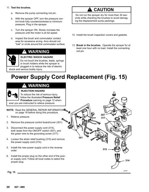
Power Supply Cord Replacement (Fig. 15)<br />
WARNING<br />
INJECTION HAZARD<br />
To reduce the risk of serious injury,<br />
follow the illustrated Pressure Relief<br />
Procedure warning on page 12 whenever<br />
you are instructed to relieve pressure.<br />
NOTE: Read the GENERAL REPAIR INFORMATION<br />
on page 18 before doing this procedure.<br />
1. Relieve pressure.<br />
307<br />
317<br />
2. Remove the pressure control board/cover (301).<br />
3. Disconnect the power supply cord (314),<br />
both leads from the ON/OFF switch (307), and<br />
the green wire to the grounding screw (317).<br />
4. Loosen the strain relief bushing (315) and remove<br />
the power supply cord (314).<br />
301<br />
5. Install the new power supply cord in the reverse<br />
order.<br />
315<br />
6. Install the proper plug on the other end of the power<br />
supply cord. Follow all local codes to select the<br />
proper plug.<br />
314<br />
Fig. 15


