

307889K ULTRA 500 AIRLESS PAINT SPRAYER - Graco Inc.
307889K ULTRA 500 AIRLESS PAINT SPRAYER - Graco Inc.
307889K ULTRA 500 AIRLESS PAINT SPRAYER - Graco Inc.

You also want an ePaper? Increase the reach of your titles
YUMPU automatically turns print PDFs into web optimized ePapers that Google loves.
Motor Brush Replacement<br />
NOTE: Replace the brushes when they have worn to<br />
less than 12 mm (1/2 in). Note that the brushes<br />
wear differently on each side of the motor , so<br />
check them both. Brush Repair Kit 222–157 is<br />
available. A new spring clip, P/N 1 10–816 may<br />
be purchased separately.<br />
WARNING<br />
INJECTION HAZARD<br />
To reduce the risk of serious injury,<br />
follow the illustrated Pressure Relief<br />
Procedure warning on page 12 whenever<br />
you are instructed to relieve pressure.<br />
NOTE: Read the GENERAL REP AIR INFORMATION<br />
on page 18 before doing this procedure.<br />
1. Relieve pressure.<br />
2. Remove the motor shield (1). Remove the inspection<br />
covers (J) and gaskets on each side of the<br />
motor. See Fig. 11.<br />
5. Inspect the commutator for excessive pitting, burning<br />
or gouging. A black color on the commutator is<br />
normal. Have the commutator resurfaced by a<br />
qualified motor repair shop if the brushes seem to<br />
wear too fast.<br />
CAUTION<br />
When installing the brushes, follow all steps carefully<br />
to avoid damaging the parts.<br />
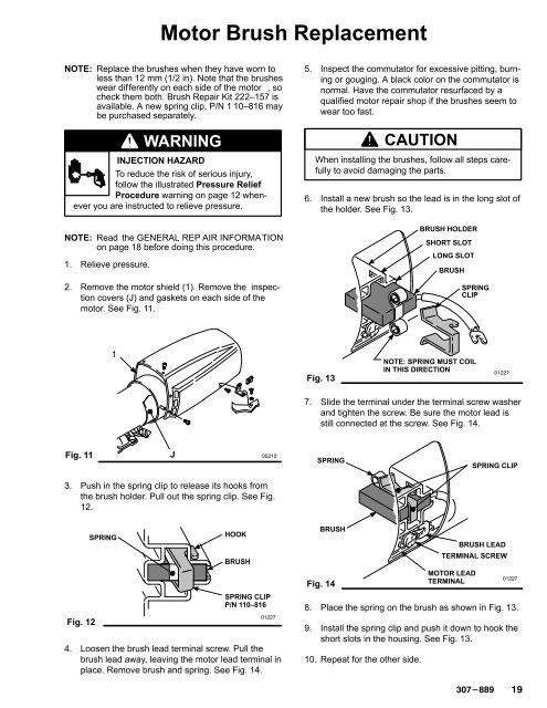
6. Install a new brush so the lead is in the long slot of<br />
the holder. See Fig. 13.<br />
BRUSH HOLDER<br />
SHORT SLOT<br />
LONG SLOT<br />
BRUSH<br />
SPRING<br />
CLIP<br />
1<br />
Fig. 13<br />
NOTE: SPRING MUST COIL<br />
IN THIS DIRECTION<br />
<br />
7. Slide the terminal under the terminal screw washer<br />
and tighten the screw. Be sure the motor lead is<br />
still connected at the screw. See Fig. 14.<br />
Fig. 11<br />
J<br />
<br />
SPRING<br />
SPRING CLIP<br />
3. Push in the spring clip to release its hooks from<br />
the brush holder. Pull out the spring clip. See Fig.<br />
12.<br />
Fig. 12<br />
SPRING<br />
HOOK<br />
BRUSH<br />
SPRING CLIP<br />
P/N 110–816<br />
<br />
4. Loosen the brush lead terminal screw. Pull the<br />
brush lead away, leaving the motor lead terminal in<br />
place. Remove brush and spring. See Fig. 14.<br />
BRUSH<br />
Fig. 14<br />
BRUSH LEAD<br />
TERMINAL SCREW<br />
MOTOR LEAD<br />
TERMINAL<br />
<br />
8. Place the spring on the brush as shown in Fig. 13.<br />
9. Install the spring clip and push it down to hook the<br />
short slots in the housing. See Fig. 13.<br />
10. Repeat for the other side.


