

307889K ULTRA 500 AIRLESS PAINT SPRAYER - Graco Inc.
307889K ULTRA 500 AIRLESS PAINT SPRAYER - Graco Inc.
307889K ULTRA 500 AIRLESS PAINT SPRAYER - Graco Inc.

You also want an ePaper? Increase the reach of your titles
YUMPU automatically turns print PDFs into web optimized ePapers that Google loves.
Drive Housing, Connecting Rod, and<br />
Crankshaft Replacement (Fig. 20)<br />
WARNING<br />
FLUID INJECTION HAZARD<br />
To reduce the risk of serious injury,<br />
follow the illustrated Pressure Relief<br />
Procedure warning on page 12 whenever<br />
you are instructed to relieve pressure.<br />
NOTE: Read the GENERAL REP AIR INFORMATION<br />
on page 18 before doing this procedure.<br />
NOTE: See Fig. 20 for Steps 1 to 15 unless otherwise<br />
noted.<br />
NOTE: Stop the sprayer at the bottom of its stroke to<br />
get the crank (57) in its lowest position. If the crank<br />
must be lowered manually, carefully rotate the blades<br />
of the fan with a screwdriver.<br />
1. Remove the displacement pump. See page 28.<br />
2. Remove the connecting rod (9). Inspect it for wear<br />
or damage. Replace the rod, if necessary.<br />
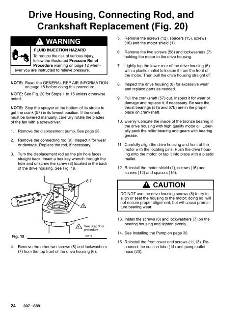
3. Turn the displacement rod so the pin hole faces<br />
straight back. Insert a hex key wrench through the<br />
hole and unscrew the screw (8) located in the back<br />
of the drive housing. See Fig. 19.<br />
<br />
8,7<br />
5. Remove the screws (12), spacers (15), screws<br />
(16) and the motor shield (1).<br />
6. Remove the two screws (58) and lockwashers (7)<br />
holding the motor to the drive housing.<br />
7. Lightly tap the lower rear of the drive housing (6)<br />
with a plastic mallet to loosen it from the front of<br />
the motor. Then pull the drive housing straight off.<br />
8. Inspect the drive housing (6) for excessive wear<br />
and replace parts as needed.<br />
9. Pull the crankshaft (57) out. Inspect it for wear or<br />
damage and replace it, if necessary. Be sure the<br />
thrust bearings (57a and 57b) are in the proper<br />
place on crankshaft.<br />
10. Evenly lubricate the inside of the bronze bearing in<br />
the drive housing with high quality motor oil. Liberally<br />
pack the roller bearing and gears with bearing<br />
grease.<br />
11. Carefully align the drive housing and front of the<br />
motor with the locating pins. Push the drive housing<br />
onto the motor, or tap it into place with a plastic<br />
mallet.<br />
12. Reinstall the motor shield (1), screws (16) and<br />
screws (12) and spacers (15).<br />
CAUTION<br />
DO NOT use the drive housing screws (8) to try to<br />
align or seat the housing to the motor; doing so will<br />
not ensure proper alignment, but will cause premature<br />
bearing wear.<br />
Fig. 19<br />
<br />
See Step 3 for<br />
procedure<br />
<br />
4. Remove the other two screws (8) and lockwashers<br />
(7) from the top front of the drive housing (6).<br />
13. Install the screws (8) and lockwashers (7) on the<br />
bearing housing and tighten evenly.<br />
14. See Installing the Pump on page 30.<br />
15. Reinstall the front cover and screws (11,13). Reconnect<br />
the suction tube (14) and pump outlet<br />
hose (23).


