TriStar® Pump Series - OWNER'S MANUAL - Pool Center
TriStar® Pump Series - OWNER'S MANUAL - Pool Center
TriStar® Pump Series - OWNER'S MANUAL - Pool Center

Create successful ePaper yourself
Turn your PDF publications into a flip-book with our unique Google optimized e-Paper software.
P/N: IS3200 Rev. J<br />
__________________________________________________________________________________________<br />
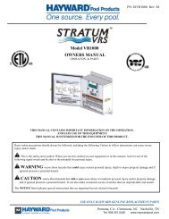
OWNER’S <strong>MANUAL</strong><br />
INSTALLATION, OPERATION & PARTS<br />
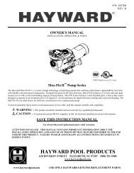
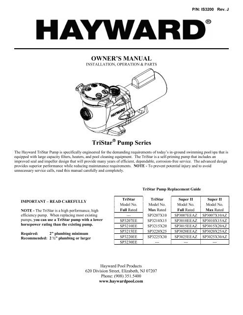
TriStar <strong>Pump</strong> <strong>Series</strong><br />
The Hayward TriStar <strong>Pump</strong> is specifically engineered for the demanding requirements of today’s in-ground swimming pool/spa that is<br />
equipped with large capacity filters, heaters, and pool cleaning equipment. The TriStar is a self-priming pump that includes an<br />
improved seal and impeller design that will provide many years of efficient, dependable, corrosion-free service. The advanced design<br />
provides superior performance while reducing maintenance requirements. NOTE - To prevent potential injury and to avoid<br />
unnecessary service calls, read this manual carefully and completely.<br />
TriStar <strong>Pump</strong> Replacement Guide<br />
IMPORTANT – READ CAREFULLY<br />
NOTE - The TriStar is a high performance, high<br />
efficiency pump. When replacing most existing<br />
pumps, you can use a TriStar pump with a lower<br />
horsepower rating than the existing pump.<br />
Required: 2” plumbing minimum<br />
Recommended: 2 ½” plumbing or larger<br />
TriStar TriStar Super II Super II<br />
Model No. Model No. Model No. Model No.<br />
Full Rated Max Rated Full Rated Max Rated<br />
--- SP3207X10 SP3007EEAZ SP3007X10AZ<br />
SP3207EE SP3210X15 SP3010EEAZ SP3010X15AZ<br />
SP3210EE SP3215X20 SP3015EEAZ SP3015X20AZ<br />
SP3215EE SP3220X25 SP3020EEAZ SP3020X25AZ<br />
SP3220EE SP3225X30 SP3025EEAZ SP3025X30AZ<br />
SP3230EE --- --- ---<br />
Hayward <strong>Pool</strong> Products<br />
620 Division Street, Elizabeth, NJ 07207<br />
Phone: (908) 351.5400<br />
www.haywardpool.com
IMPORTANT SAFETY INSTRUCTIONS<br />
Basic safety precautions should always be followed, including the following: Failure to follow instructions can cause<br />
severe injury and/or death.<br />
This is the safety-alert symbol. When you see this symbol on your equipment or in this manual, look for one of<br />
the following signal words and be alert to the potential for personal injury.<br />
WARNING warns about hazards that could cause serious personal injury, death or major property damage and<br />
if ignored presents a potential hazard.<br />
CAUTION warns about hazards that will or can cause minor or moderate personal injury and/or property<br />
damage and if ignored presents a potential hazard. It can also make consumers aware of actions that are<br />
unpredictable and unsafe.<br />
The NOTICE label indicates special instructions that are important but not related to hazards.<br />
WARNING - Read and follow all instructions in this owner’s manual and on the equipment. Failure to<br />
follow instructions can cause severe injury and/or death.<br />
WARNING – Suction Entrapment Hazard.<br />
Suction in suction outlets and/or suction outlet covers which are, damaged, broken, cracked, missing, or unsecured can cause severe injury<br />
and/or death due to the following entrapment hazards:<br />
Hair Entrapment- Hair can become entangled in suction outlet cover.<br />
Limb Entrapment- A limb inserted into an opening of a suction outlet sump or suction outlet cover that is damaged, broken, cracked,<br />
missing, or not securely attached can result in a mechanical bind or swelling of the limb.<br />
Body Suction Entrapment- A negative pressure applied to a large portion of the body or limbs can result in an entrapment.<br />
Evisceration/ Disembowelment - A negative pressure applied directly to the intestines through an unprotected suction outlet sump or<br />
suction outlet cover which is, damaged, broken, cracked, missing, or unsecured can result in evisceration/ disembowelment.<br />
Mechanical Entrapment- There is potential for jewelry, swimsuit, hair decorations, finger, toe or knuckle to be caught in an opening of a<br />
suction outlet cover resulting in mechanical entrapment.<br />
WARNING - To Reduce the risk of Entrapment Hazards:<br />
o When outlets are small enough to be blocked by a person, a minimum of two functioning suction outlets per pump must be<br />
installed. Suction outlets in the same plane (i.e. floor or wall), must be installed a minimum of three feet (3’) [1 meter] apart, as<br />
measured from near point to near point.<br />
o Dual suction fittings shall be placed in such locations and distances to avoid “dual blockage” by a user.<br />
o Dual suction fittings shall not be located on seating areas or on the backrest for such seating areas.<br />
o The maximum system flow rate shall not exceed the flow rating of as listed on Table 1.<br />
o Never use <strong>Pool</strong> or Spa if any suction outlet component is damaged, broken, cracked, missing, or not securely attached.<br />
o Replace damaged, broken, cracked, missing, or not securely attached suction outlet components immediately.<br />
o In addition two or more suction outlets per pump installed in accordance with latest ASME, APSP Standards and CPSC<br />
guidelines, follow all National, State, and Local codes applicable.<br />
o Installation of a vacuum release or vent system, which relieves entrapping suction, is recommended.<br />
WARNING – Failure to remove pressure test plugs and/or plugs used in winterization of the pool/spa from the<br />
suction outlets can result in an increase potential for suction entrapment as described above.<br />
WARNING – Failure to keep suction outlet components clear of debris, such as leaves, dirt, hair, paper and<br />
other material can result in an increase potential for suction entrapment as described above.<br />
WARNING – Suction outlet components have a finite life, the cover/grate should be inspected frequently and<br />
replaced at least every ten years or if found to be damaged, broken, cracked, missing, or not securely attached.<br />
CAUTION – Components such as the filtration system, pumps and heater must be positioned so as to prevent<br />
their being used as means of access to the pool by young children.<br />
WARNING – Never operate or test the circulation system at more than 50 PSI.<br />
WARNING – Never change the filter control valve position while the pump is running.<br />
WARNING – To reduce risk of injury, do not permit children to use or climb on this product. Closely supervise children at all<br />
times. Components such as the filtration system, pumps, and heaters must be positioned to prevent children from using them as a means of<br />
access to the pool.<br />
WARNING – Hazardous Pressure. <strong>Pool</strong> and spa water circulation systems operate under hazardous pressure during start up,<br />
normal operation, and after pump shut off. Stand clear of circulation system equipment during pump start up. Failure to follow safety and<br />
USE ONLY HAYWARD GENUINE REPLACEMENT PARTS<br />
Page 2 of 16 TriStar <strong>Pump</strong> <strong>Series</strong> IS3200 Rev. J
operation instructions could result in violent separation of the pump housing and cover, and/or filter housing and clamp due to pressure in<br />
the system, which could cause property damage, severe personal injury, or death. Before servicing pool and spa water circulation system,<br />
all system and pump controls must be in off position and filter manual air relief valve must be in open position. Before starting system<br />
pump, all system valves must be set in a position to allow system water to return back to the pool. Do not change filter control valve<br />
position while system pump is running. Before starting system pump, fully open filter manual air relief valve. Do not close filter manual<br />
air relief valve until a steady stream of water (not air or air and water) is discharged.<br />
WARNING – Separation Hazard. Failure to follow safety and operation instructions could result in violent separation of<br />
pump and/or filter components. Strainer cover must be properly secured to pump housing with strainer cover lock ring. Before servicing<br />
pool and spa circulation system, filters manual air relief valve must be in open position. Do not operate pool and spa circulation system if a<br />
system component is not assembled properly, damaged, or missing. Do not operate pool and spa circulation system unless filter manual air<br />
relief valve body is in locked position in filter upper body.<br />
WARNING – Risk of Electric Shock. All electrical wiring MUST be in conformance with applicable local codes, regulations,<br />
and the National Electric Code (NEC). Hazardous voltage can shock, burn, and cause death or serious property damage. To reduce the<br />
risk of electric shock, do NOT use an extension cord to connect unit to electric supply. Provide a properly located electrical receptacle.<br />
Before working on any electrical equipment, turn off power supply to the equipment.<br />
WARNING – To reduce the risk of electric shock replace damaged wiring immediately. Locate conduit to prevent abuse from<br />
lawn mowers, hedge trimmers and other equipment.<br />
WARNING – Electrical ground all electrical equipment before connecting to electrical power supply. Failure to ground all<br />
electrical equipment can cause serious or fatal electrical shock hazard.<br />
WARNING – Do NOT ground to a gas supply line.<br />
WARNING – To avoid dangerous or fatal electrical shock, turn OFF power to all electrical equipment before working on<br />
electrical connections.<br />
WARNING – Failure to bond all electrical equipment to pool structure will increase risk for electrocution and could result in<br />
injury or death. To reduce the risk of electric shock, see installation instructions and consult a professional electrician on how to bond all<br />
electrical equipment. Also, contact a licensed electrician for information on local electrical codes for bonding requirements.<br />
Notes to electrician: Use a solid copper conductor, size 8 or larger. Run a continuous wire from external bonding lug to reinforcing rod<br />
or mesh. Connect a No. 8 AWG (8.4 mm 2 ) [No. 6 AWG (13.3 mm 2 ) for Canada] solid copper bonding wire to the pressure wire connector<br />
provided on the electrical equipment and to all metal parts of swimming pool, spa, or hot tub, and metal piping (except gas piping), and<br />
conduit within 5 ft. (1.5 m) of inside walls of swimming pool, spa, or hot tub.<br />
IMPORTANT - Reference NEC codes for all wiring standards including, but not limited to, grounding, bonding and other general wiring<br />
procedures.<br />
WARNING – Risk of Electric Shock. Connect only to a branch circuit protected by a ground-fault circuit-interrupter (GFCI).<br />
Contact a qualified electrician if you cannot verify that the circuit is protected by a GFCI.<br />
WARNING – Risk of Electric Shock . The electrical equipment must be connected only to a supply circuit that is protected by a<br />
ground-fault circuit-interrupter (GFCI). Such a GFCI should be provided by the installer and should be tested on a routine basis. To test<br />
the GFCI, push the test button. The GFCI should interrupt power. Push reset button. Power should be restored. If the GFCI fails to<br />
operate in this manner, the GFCI is defective. If the GFCI interrupts power to the electrical equipment without the test button being<br />
pushed, a ground current is flowing, indicating the possibility of an electrical shock. Do not use this electrical equipment. Disconnect the<br />
electrical equipment and have the problem corrected by a qualified service representative before using.<br />
CAUTION – This pump is intended for use with permanently-installed pools and may be used with hot tubs and spas if so<br />
marked. Do not use with storable pools. A permanently-installed pool is constructed in or on the ground or in a building such that it<br />
cannot be readily disassembled for storage. A storable pool is constructed so that it is capable of being readily disassembled for storage<br />
and reassembled to its original integrity.<br />
SAVE THESE INSTRUCTIONS<br />
USE ONLY HAYWARD GENUINE REPLACEMENT PARTS<br />
Page 3 of 16 TriStar <strong>Pump</strong> <strong>Series</strong> IS3200 Rev. J
General Information<br />
Introduction<br />
This manual contains information for the proper installation and operation of the Hayward TriStar <strong>Pump</strong> <strong>Series</strong>. The<br />
instructions in this manual MUST be followed precisely. Failure to install according to defined instructions will void<br />
warranty.<br />
Product Benefits<br />
The new TriStar <strong>Pump</strong>’s advanced fluid dynamic design optimizes the three essential pump elements to deliver superior flow,<br />
energy efficiency, and quietness. Plus, the heavy-duty pump and motor construction operates cooler for years of<br />
dependability. It is the first to feature a Tri-Lock cam and ramp strainer cover design that closes with less than a quarter turn,<br />
and the TriStar’s super-sized, smooth no-rib basket with extra leaf-holding capacity is easy to clean. TriStar has a variety of<br />
bases available to seamlessly retrofit to existing filtration systems.<br />
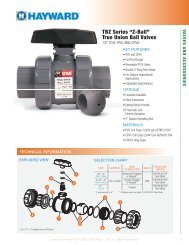
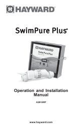
Product Specifications<br />
Installation Instructions<br />
HP FR “A” MR “A”<br />
½ 13 5/8” -<br />
¾ 13 7/8” 13 3/8”<br />
1 14 3/8” 13 7/8”<br />
1 * 14 3/8” -<br />
1 ½ 14 7/8” 13 7/8”<br />
1 ½ * 14 7/8” 14 3/8”<br />
2 14 7/8” 15 1/8”<br />
2 * 14 7/8” 14 7/8”<br />
2 ** 13 1/2” -<br />
2 ½ - 14 7/8”<br />
2 ½ * - 14 7/8”<br />
3 17 1/8” 15 5/8”<br />
3 ** 14 1/2” -<br />
5 17 1/8” -<br />
* Two-Speed <strong>Pump</strong><br />
** Three-Phase <strong>Pump</strong><br />
WARNING – This product should be installed and serviced only by a qualified professional.<br />
<strong>Pump</strong> Location<br />
Locate pump as close to pool as practical and run suction lines as direct as possible to reduce friction<br />
loss. Suction lines should have continuous slope upward from lowest point in line. Joints must be tight<br />
(but not over-tightened). Suction line diameter must equal or be larger than the discharge line diameter.<br />
Though the pump is designed for outdoor use, it is strongly advised to place pump and filter in the<br />
shade to shield them from continuous direct heat. Select a well-drained area that will not flood when it rains. Do NOT<br />
install pump and filter in a damp or non-ventilated location. Keep motor clean. <strong>Pump</strong> motors require free circulation of<br />
air for cooling.<br />
<strong>Pump</strong> Mounting<br />
Install pump on a level concrete slab or other rigid base to meet all local and national codes. Secure pump to base with<br />
screws or bolts to further reduce vibration and stress on pipe or hose joints. The base must be level, rigid, and vibration free.<br />
<strong>Pump</strong> mount must:<br />
• Allow pump inlet height to be as close to water level as possible.<br />
• Allow use of short, direct suction pipe (to reduce friction losses).<br />
• Allow for gate valves in suction and discharge piping.<br />
• Be protected from excess moisture and flooding.<br />
• Allow adequate access for servicing pump and piping.<br />
USE ONLY HAYWARD GENUINE REPLACEMENT PARTS<br />
Page 4 of 16 TriStar <strong>Pump</strong> <strong>Series</strong> IS3200 Rev. J
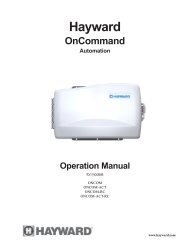
Pipe Sizing Chart<br />
Pipe Size<br />
[mm]<br />
MAXIMUM RECOMMENDED SYSTEM FLOW RATE BY PIPE SIZE<br />
Flow Rate<br />
GPM [LPM]<br />
Suction Pipe<br />
Length *<br />
Pipe Size<br />
[mm]<br />
Flow Rate<br />
GPM [LPM]<br />
Suction Pipe<br />
Length *<br />
Pipe Size<br />
[mm]<br />
Flow Rate<br />
GPM [LPM]<br />
* NOTE - It is recommended that a minimum length of straight piping (shown as “L” in above diagram), equivalent<br />
to 5 pipe size diameters, be used between the pump suction inlet and any plumbing fittings (elbows, valves, etc.).<br />
Suction Pipe<br />
Length *<br />
1” [32] 20 [75] 5” 1 ½” [50] 45 [170] 7 ½” 2 ½” [75] 110 [415] 12 ½”<br />
1 ¼” [40] 30 [110] 6 ¼” 2” [63] 80 [300] 10” 3” [90] 160 [600] 15”<br />
WARNING – Hazardous Pressure. <strong>Pump</strong>s, filters, and other equipment/ components of a<br />
swimming pool filtration system operate under pressure. Incorrectly installed and/or improperly tested<br />
filtration equipment and/or components may fail resulting in severe personal injury or death.<br />
Plumbing<br />
Use Teflon tape to seal threaded connections on molded plastic components. All plastic fittings must be new or thoroughly<br />
cleaned before use. NOTE - Do NOT use Plumber’s Pipe Dope as it may cause cracking of the plastic components.<br />
When applying Teflon tape to plastic threads, wrap the entire threaded portion of the male fitting with one to two layers of<br />
tape. Wind the tape clockwise as you face the open end of the fitting, beginning at the end of the fitting. The pump suction<br />
and outlet ports have molded-in thread stops. Do NOT attempt to force hose connector fitting past this stop. It is only<br />
necessary to tighten fittings enough to prevent leakage. Tighten fitting by hand and then use a tool to engage fitting an<br />
additional 1 ½ turns. Use care when using Teflon tape as friction is reduced considerably; do NOT over-tighten fitting or<br />
you may cause damage. If leaks occur, remove connector, clean off old Teflon tape, re-wrap with one to two additional<br />
layers of Teflon tape, and re-install connector.<br />
Fittings restrict flow. For better efficiency, use the fewest possible fittings (but at least two suction outlets). Avoid fittings<br />
that could cause an air trap. <strong>Pool</strong> and spa fittings MUST conform to the International Association of Plumbing and<br />
Mechanical Officials (IAPMO) standards. Use a non-entrapping suction fitting in pool (multiple drains) or double suction<br />
(skimmer and main drain).<br />
Electrical<br />
WARNING – All electrical wiring MUST be in conformance with all applicable local codes,<br />
regulations, and the National Electric Code (NEC). Ground and bond motor before connecting to<br />
electrical power supply. Failure to ground and bond pump motor can cause serious or fatal electrical<br />
shock hazard. Do NOT ground to a gas supply line. To avoid dangerous or fatal electrical shock, turn<br />
OFF power to motor before working on electrical connections. Fire Hazard - match supply voltage<br />
to motor nameplate voltage. Insure that the electrical supply available agrees with the motor’s<br />
voltage, phase, and cycle, and that the wire size is adequate for the HP (kW) rating and distance from<br />
the power source. Use copper conductors only.<br />
Voltage<br />
Voltage at motor MUST NOT be more than 10% above or below motor name plate rated voltage, or motor may<br />
overheat, causing overload tripping and reduced component life. If voltage is less than 90% or more than 110% of<br />
rated voltage when motor is running at full load, consult power company.<br />
Grounding and Bonding<br />
Install, ground, bond, and wire motor in accordance with local or national electrical code requirements.<br />
USE ONLY HAYWARD GENUINE REPLACEMENT PARTS<br />
Page 5 of 16 TriStar <strong>Pump</strong> <strong>Series</strong> IS3200 Rev. J
Permanently ground motor. Use green ground terminal provided under motor canopy or access place; use size and<br />
type wire required by code. Connect motor ground terminal to electrical service ground.<br />
Bond motor to pool structure. Bonding will connect all metal parts within and around the pool with a continuous<br />
wire. Bonding reduces the risk of a current passing between bonded metal objects, which could potentially cause<br />
electrical shock if grounded or shorted. Reference NEC codes for all wiring standards including, but not limited<br />
to, grounding, bonding and general wiring procedures.<br />
Use a solid copper conductor, size 8 or larger. Run wire from external bonding lug to reinforcing rod or mesh.<br />
Connect a No. 8 AWG (8.4 mm 2 ) solid copper bonding wire to the pressure wire connector provided on the motor<br />
housing and to all metal parts of swimming pool, spa, or hot tub, and to all electrical equipment, metal piping<br />
(except gas piping), and conduit within 5 ft. (1.5 m) of inside walls of swimming pool, spa, or hot tub.<br />
Wiring<br />
WARNING – All electrical wiring MUST be in conformance with all applicable local codes, regulations,<br />
and the National Electric Code (NEC).<br />
<strong>Pump</strong> MUST be permanently connected to circuit. If other lights or appliances are also on the same circuit, be sure<br />
to add their amp loads before calculating wire and circuit breaker sizes. Use the load circuit breaker as the Master<br />
On-Off switch.<br />
Motor Specifications<br />
Full Rate <strong>Pump</strong>s<br />
Max Rate <strong>Pump</strong>s<br />
50 Hz <strong>Pump</strong>s<br />
Motor Brake Horsepower Motor Rated Horsepower Motor Electric V/A Wire Size / Breaker<br />
HP (kW) HP (kW) Voltage Amps AWG Amps<br />
0.99 (0.74) 0.50 (0.37) 208 - 230 / 115 5.3 - 4.9 / 9.8 14 10 / 15<br />
1.39 (1.04) 0.75 (0.56) 208 - 230 / 115 7.0 - 6.2 / 12.4 14 10 / 15<br />
1.85 (1.38) 1.00 (0.75) 208 - 230 / 115 8.5 - 7.4 / 14.8 14 / 12 15 / 20<br />
2.40 (1.79) 1.50 (1.12) 208 - 230 / 115 11.2 - 10.2 / 20.4 14 / 10 15 / 30<br />
2.70 (2.01) 2.00 (1.49) 208 - 230 11.8 - 11.0 14 15<br />
2.70 (2.01) ** 2.00 (1.49) ** 208 - 230 ** 7.0 - 6.6 ** 14 ** 10 **<br />
3.60 (2.69) 3.00 (2.24) 208 - 230 16.0 - 14.8 12 20<br />
3.60 (2.69) * 3.00 (2.24) * 208 - 230 / 460 * 9.6 - 9.4 / 4.7 * 14 * 15 / 10 *<br />
5.00 (3.73) 5.00 (3.73) 208 - 230 21.0 - 19.4 10 30<br />
1.85 / 0.22 (1.38 / 0.16) 1.00 / 0.12 (0.75 / 0.09) 208 - 230 8.6 - 8.2 ¹ 14 15<br />
2.40 / 0.28 (1.79 / 0.21) 1.50 / 0.18 (1.12 / 0.13) 208 - 230 11.4 - 10.4 ² 14 15<br />
2.70 / 0.33 (2.01 / 0.25) 2.00 / 0.25 (1.49 / 0.19) 208 - 230 12.4 - 11.2 ³ 14 15<br />
0.94 (0.70) 0.75 (0.56) 230 / 115 5.4 / 10.8 14 10 / 15<br />
1.25 (0.93) 1.00 (0.75) 230 / 115 7.0 / 14.0 14 / 12 10 / 20<br />
1.65 (1.23) 1.50 (1.12) 230 / 115 7.7 / 15.4 14 / 12 10 / 20<br />
2.20 (1.64) 2.00 (1.49) 230 / 115 10.8 / 21.6 14 / 10 15 / 30<br />
2.60 (1.94) 2.50 (1.86) 230 11.5 14 15<br />
3.45 (2.57) 3.00 (2.24) 230 13.5 12 20<br />
1.85 / 0.22 (1.38 / 0.16) 1.50 / 0.18 (1.12 / 0.13) 208 - 230 8.6 - 8.2 ¹ 14 15<br />
2.40 / 0.28 (1.79 / 0.21) 2.00 / 0.25 (1.49 / 0.19) 208 - 230 11.4 - 10.4 ² 14 15<br />
2.70 / 0.33 (2.01 / 0.25) 2.50 / 0.30 (1.86 / 0.22) 208 - 230 12.4 - 11.2 ³ 14 15<br />
0.75 (0.56) 0.75 (0.56) 220 / 110 7.0 / 14.0 14 / 12 10 / 20<br />
1.00 (0.75) 1.00 (0.75) 220 / 110 8.0 / 16.0 14 / 12 10 / 20<br />
1.50 (1.12) 1.50 (1.12) 220 / 110 9.8 / 19.6 14 / 10 15 / 30<br />
2.00 (1.49) 2.00 (1.49) 220 11.0 14 15<br />
3.00 (2.24) 3.00 (2.24) 220 12.0 14 15<br />
3.00 (2.24) * 3.00 (2.24) * 380 - 415 / 190 * 4.9 - 4.8 / 9.8 * 14 * 10 / 15 *<br />
¹ , ² , ³ Low Speed Amps: (¹ 2.8 - 3.0) (² 3.2 - 3.4) (³ 3.8 - 4.1)<br />
* Three-Phase (3Φ) <strong>Pump</strong> - motor starter required<br />
** Three-Phase (3Φ) <strong>Pump</strong> - variable-speed applications only (Not available as a stand-alone pump. May only be used with SP3220VSC.)<br />
USE ONLY HAYWARD GENUINE REPLACEMENT PARTS<br />
Page 6 of 16 TriStar <strong>Pump</strong> <strong>Series</strong> IS3200 Rev. J
Start-Up & Operation<br />
Prior to Start-Up<br />
NOTE - If it is necessary to perform a pressure test, prior to initial use to ensure pump is functioning properly, then the<br />
following criteria should be maintained for this test:<br />
1. Have a professional perform this test.<br />
2. Ensure all pump and system components are sealed properly to prevent leaks.<br />
3. Remove any trapped air in the system by fully opening filter manual air relief valve until a<br />
steady stream of water (not air or air and water mix) is discharged from the valve.<br />
4. Allow no more than 50 psi (345 kPa) at a water temperature no higher than 100 F (38 C).<br />
5. Run pressure test for no longer than 24 hours. Immediately inspect all parts to verify they are<br />
intact and functioning properly.<br />
WARNING - If pump is being pressure tested (50 PSI MAXIMUM), be sure pressure has<br />
been released, using the filter manual air relief valve, before removing strainer cover.<br />
WARNING – All suction and discharge valves MUST be OPEN, as well as filter air relief<br />
valve (if available) on filter, when starting the circulating pump system. Failure to do so could result in<br />
severe personal injury.<br />
Starting/Priming the <strong>Pump</strong>:<br />
<strong>Pump</strong>s with single speed motors are self priming to 10 ft. and pumps with 2 speed motors are self priming to 10 ft. on high<br />
speed only. Fill strainer housing with water to suction pipe level. If water leakage occurs from anywhere on the pump or<br />
filter, DO NOT start the pump. If no leakage occurs, stand at least 10 feet from pump and/or filter and proceed with starting<br />
the pump.<br />
WARNING – Return to filter to close filter manual air relief valve when a steady stream of water (not air or air<br />
and water) is discharged from valve. Failure to do so could result in severe personal injury.<br />
ATTENTION – NEVER OPERATE THE PUMP WITHOUT WATER. Water acts as a coolant and<br />
lubricant for the mechanical shaft seal. NEVER run pump dry. Running pump dry may damage seals, causing leakage,<br />
flooding, and voids warranty. Fill strainer housing with water before starting motor.<br />
ATTENTION – Do NOT add chemicals to pool/spa system directly in front of pump suction. Adding undiluted<br />
chemicals may damage pump and voids warranty.<br />
ATTENTION – Before removing strainer cover:<br />
1. STOP PUMP before proceeding.<br />
2. CLOSE VALVES in suction and outlet pipes.<br />
3. RELEASE ALL PRESSURE from pump and piping system using filter manual air relief valve. See filter<br />
owner’s manual for more details.<br />
4. If water source is higher than the pump, pump will prime itself when suction and outlet valves are opened. If<br />
water source is lower than the pump, unscrew and remove strainer cover; fill strainer housing with water.<br />
5. Clean and lubricate strainer cover O-ring with "Jack's 327" if necessary.<br />
6. Replace strainer cover on strainer housing; turn clockwise to tighten cover.<br />
NOTE - Tighten strainer cover lock ring by hand only (no wrenches).<br />
USE ONLY HAYWARD GENUINE REPLACEMENT PARTS<br />
Page 7 of 16 TriStar <strong>Pump</strong> <strong>Series</strong> IS3200 Rev. J
Before re-starting pump, see “Starting/Priming the <strong>Pump</strong>” instructions.<br />
ATTENTION – Wait five (5) seconds before re-starting pump. Failure to do so may cause reverse rotation of<br />
motor and consequent serious pump damage.<br />
Turn on power and wait for pump to prime, which may take up to five (5) minutes. Priming time will depend on vertical<br />
length of suction lift and horizontal length of suction pipe. If pump does NOT prime within five minutes, stop motor and<br />
determine cause. Be sure all suction and discharge valves are open when pump is running. See Troubleshooting Guide.<br />
Maintenance<br />
• Clean strainer basket regularly. Do NOT strike basket to clean. Inspect strainer cover gasket regularly and replace as<br />
necessary.<br />
• Hayward pumps have self-lubricating motor bearings and shaft seals. No lubrication is necessary.<br />
• Keep motor clean. Insure motor air vents are free from obstruction to avoid damage. Do NOT use water to hose off<br />
motor.<br />
• Occasionally, shaft seals must be replaced, due to wear or damage. Replace with genuine Hayward seal assembly kit.<br />
See “Shaft Seal Change Instructions” in this manual.<br />
Storage/Winterization<br />
WARNING – Separation Hazard. Do not purge the system with compressed air. Purging<br />
the system with compressed air can cause components to explode, with risk of severe injury or death to<br />
anyone nearby. Use only a low pressure (below 5 PSI), high volume blower when air purging the pump,<br />
filter, or piping.<br />
ATTENTION – Allowing the pump to freeze will void the warranty.<br />
ATTENTION – Use ONLY propylene glycol as antifreeze in your pool/spa system. Propylene glycol is nontoxic<br />
and will not damage plastic system components; other anti-freezes are highly toxic and may damage plastic components<br />
in the system.<br />
Drain all water from pump and piping when expecting freezing temperatures or when storing pump for a long time (see<br />
instructions below). Gravity drain system as far as possible.<br />
Keep motor dry and covered during storage. To avoid condensation/corrosion problems, do NOT cover or wrap pump with<br />
plastic film or bags.<br />
Storing <strong>Pump</strong> for Winterization<br />
WARNING – To avoid dangerous or fatal electrical shock hazard, turn OFF power to motor<br />
before draining pump. Failure to disconnect power may result in serious personal injury or death.<br />
1. Drain water level below all inlets to the pool.<br />
2. Remove drain plugs and strainer cover from strainer housing. (See Parts Diagram on page 11 of<br />
this manual for pump component locations.)<br />
3. Disconnect pump from mounting pad, wiring (after power has been turned OFF), and piping.<br />
4. Once the pump is removed of water, re-install the strainer cover and drain plugs. Store pump in a<br />
dry area.<br />
USE ONLY HAYWARD GENUINE REPLACEMENT PARTS<br />
Page 8 of 16 TriStar <strong>Pump</strong> <strong>Series</strong> IS3200 Rev. J
Shaft Seal Change Instructions<br />
IMPORTANT SAFETY INSTRUCTIONS<br />
PLEASE READ AND FOLLOW ALL INSTRUCTIONS<br />
When servicing electrical equipment, basic safety precautions should always be observed including the following. Failure to follow<br />
instructions may result in injury.<br />
A. WARNING – To reduce risk of injury, do not permit children to use this product.<br />
B. Disconnect all electrical power service to pump before beginning shaft seal replacement.<br />
C. Only qualified personnel should attempt rotary seal replacement. Contact your local authorized Hayward Dealer or<br />
service center if you have any questions.<br />
Exercise extreme care in handling both the rotating and the stationary sections of the two-part replacement seal. Foreign matter or<br />
improper handling will easily scratch the graphite and ceramic sealing surfaces.<br />
Removing the Motor Assembly (See Parts Diagram on page 11 of this manual for pump component locations.)<br />
1. Remove the six (6) 5/16" x 2" hex head bolts (item #17), which hold the motor assembly to the pump/strainer<br />
housing (item #3), using a 1/2" wrench or socket.<br />
2. Slide the motor assembly out of the pump/strainer housing (item #3), exposing the diffuser (item #9). Remove the<br />
two diffuser screws (item #7), and pull the diffuser (item #9) off of the seal plate (item #15) to expose the impeller<br />
(item #12).<br />
Removing the Impeller (See Parts Diagram on page 11 of this manual for pump component locations.)<br />
3. Remove the motor canopy by removing the two (2) screws and pulling the canopy away from the motor.<br />
4. To prevent motor shaft from turning, carefully place a 7/16" open-end wrench over the two (2) flats on the end of<br />
the shaft.<br />
5. Rotate the impeller screw (item #10) clockwise (note that screw has left-hand thread) and remove. Remove the<br />
impeller (item #12) by rotating counterclockwise.<br />
Removing the Ceramic Seat (See Parts Diagram on page 11 of this manual for pump component locations.)<br />
6. Remove the spring seal assembly (item #13) and seal plate (item #15) from the motor by removing the four (4) 3/8”<br />
x 1” bolts (item #18) that secure it to the motor, using a 9/16" wrench or socket. Remove the motor support bracket<br />
(item #20) from the seal plate (item #15).<br />
7. Press the ceramic seat with rubber cup out of the seal plate (item #15). If tight, use a small screwdriver to tap seal<br />
out.<br />
STOP - Clean all recesses & parts to be reassembled. Inspect gaskets & replace if necessary.<br />
Seal Installation (See Parts Diagram on page 11 of this manual for pump component locations.)<br />
8. Clean and lightly lubricate the motor shaft and seal recesses in the seal plate (item #15) with a dilute solution of nongranulated<br />
liquid-type soap. Gently wipe the polished face of the ceramic seal with a soft cotton cloth. Lubricate the<br />
rubber cup on the ceramic seat and press it firmly into the recess of the seal plate (item #15), with the polished<br />
ceramic surface facing out.<br />
9. Reassemble the motor to the seal plate (item #15) using the four (4) 3/8” x 1” bolts (item #18), and re-attach the<br />
motor support (item #20) to the seal plate (item #15).<br />
10. Gently wipe the black, polished surface of the spring seal assembly (item #13) with a soft cotton cloth.<br />
11. Press the spring seal assembly (item #13) onto the motor shaft, with the black polished surface facing the ceramic<br />
seat.<br />
Replacing the Impeller and Diffuser (See Parts Diagram on page 11 of this manual for pump component locations.)<br />
12. Screw the impeller (item #12) onto the motor shaft in a clockwise direction, and screw the impeller screw (item #10)<br />
into the motor shaft in a counterclockwise direction. Tighten snugly by holding motor shaft with wrench as noted in<br />
step #4. Place the impeller ring (item #11) back onto the impeller (item #12), with flange facing towards the<br />
diffuser (item #9).<br />
13. Place the diffuser (item #9) over the impeller (item #12) and onto the seal plate (item #15), aligning the three pins on<br />
the diffuser (item #9) with the three holes on the seal plate (item #15). Replace the two diffuser screws (item #7).<br />
USE ONLY HAYWARD GENUINE REPLACEMENT PARTS<br />
Page 9 of 16 TriStar <strong>Pump</strong> <strong>Series</strong> IS3200 Rev. J
Replacing the Motor Assembly (See Parts Diagram on page 11 of this manual for pump component locations.)<br />
14. Re-attach motor canopy using the two (2) hex headed screws. Slide the motor assembly, with the diffuser (item #9)<br />
in place, into pump/strainer housing (item #3), being careful not to disturb the diffuser gasket (item #8).<br />
15. Fasten assembly to pump/strainer housing (item #3) using the six (6) 5/16" x 2" bolts (item #17). (Be sure housing<br />
gasket (item #14) is in place, and lubricated. Replace if damaged). Tighten bolts alternately and evenly to 185 inchpounds<br />
according to housing bolt torque pattern detail.<br />
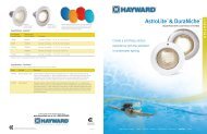
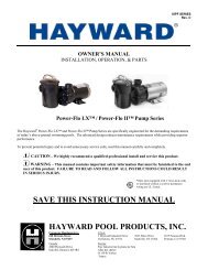
Replacement Parts<br />
Parts Diagram<br />
Detail of motor<br />
canopy with screws.<br />
Parts Listing<br />
Ref. No. Part No. Description Ctn. Qty.<br />
1 SPX3200UNKIT Union Connector Kit (Includes Union Nut, Union Connector, Union Gasket - 2 ea.) 1<br />
2 SPX3200UG Union Gasket 1<br />
3 SPX3200A <strong>Pump</strong> Strainer Housing, 2” x 2 1/2” with Drain Plugs, threaded style 1<br />
4 SPX3200DLS Strainer Cover Kit (Includes Strainer Cover, Lock Ring, O-Ring) 10<br />
4 SPX3200DLSB Strainer Cover Kit (Biguanide Sanitizer Applications Only; NOT Pressure Testable) 10<br />
5 SPX3200S Strainer Cover O-Ring 10<br />
6 SPX3200M Strainer Basket 15<br />
USE ONLY HAYWARD GENUINE REPLACEMENT PARTS<br />
Page 10 of 16 TriStar <strong>Pump</strong> <strong>Series</strong> IS3200 Rev. J
Ref. No. Part No. Description Ctn. Qty.<br />
7 SPX3200Z8 Diffuser Screw 1<br />
8 SPX4000Z1 Diffuser O-Ring 10<br />
9 SPX3200B3 Diffuser 1<br />
10 SPX3200Z1 Impeller Screw 1<br />
11 SPX3021R Impeller Ring 1<br />
12 SPX3205C Impeller for ½ HP with Impeller Screw 10<br />
12 SPX3207C Impeller for ¾ HP with Impeller Screw 10<br />
12 SPX3207CM Impeller for 1 HP with Impeller Screw (Max Rate) 10<br />
12 SPX3210C Impeller for 1 HP with Impeller Screw (Full Rate) 10<br />
12 SPX3215C Impeller for 1 ½ HP with Impeller Screw 10<br />
12 SPX3220C Impeller for 2 HP with Impeller Screw (Full Rate) 10<br />
12 SPX3220CM Impeller for 2 ½ HP with Impeller Screw (Max Rate) 10<br />
12 SPX3230C Impeller for 3 HP with Impeller Screw 10<br />
12 SPX3230C5 Impeller for 5 HP with Impeller Screw 10<br />
13 SPX3200SA Shaft Seal Assembly 10<br />
14 SPX3200T Housing O-Ring 10<br />
15 SPX3200E Seal Plate 1<br />
16 SPX3200Z211 Housing Insert/Seal Plate Spacer Kit 1<br />
17 SPX3200Z3 Housing Bolt 10<br />
18 SPX3200Z5 Motor Bolt 1<br />
19 SPX4000FG Drain Plug with O-Ring 10<br />
20 SPX3200GA Bracket, Motor Support, TriStar 1<br />
21 * SPX3200WF Base, Short Riser, TriStar 1<br />
22 * SPX3200SR Base, Tall Riser, TriStar 1<br />
<strong>Pump</strong> SKU Detail<br />
Full Rate <strong>Pump</strong>s<br />
Max Rate <strong>Pump</strong>s<br />
50 Hz<br />
<strong>Pump</strong>s<br />
Model P/N Motor P/N Power End P/N (1) Impeller P/N<br />
SP3205EE SPX3205Z1BER SPX3205Z1PE SPX3205C<br />
SP3207EE SPX3207Z1BER SPX3207Z1PE SPX3207C<br />
SP3210EE SPX3210Z1BER SPX3210Z1PE SPX3210C<br />
SP3215EE SPX3215Z1BER SPX3215Z1PE SPX3215C<br />
SP3220EE SPX3220Z1BER SPX3220Z1PE SPX3220C<br />
SP3230EE SPX3230Z1BER SPX3230Z1PE SPX3230C<br />
SP3250EE SPX3240Z1MER SPX3250Z1PE SPX3230C5<br />
SP32102EE SPX3210Z2BER SPX3210Z2PE SPX3210C<br />
SP32152EE SPX3215Z2BER SPX3215Z2PE SPX3215C<br />
SP32202EE SPX3220Z2BER SPX3220Z2PE SPX3220C<br />
SP322063EEV (2) SPX3220Z1DRV (2) SPX3220Z1PE3V (2) SPX3215C<br />
SP323063EE SPX3230Z1DR SPX3230Z1PE3 SPX3230C<br />
SP3205X7 SPX3205Z1MR SPX3205X7Z1PE SPX3205C<br />
SP3207X10 SPX3207Z1MR SPX3207X10Z1PE SPX3207CM<br />
SP3210X15 SPX3210Z1MR SPX3210X15Z1PE SPX3210C<br />
SP3215X20 SPX3215Z1MR SPX3215X20Z1PE SPX3215C<br />
SP3220X25 SPX3220Z1MR SPX3220X25Z1PE SPX3220CM<br />
SP3225X30 SPX3225Z1MR SPX3225X30Z1PE SPX3230C<br />
SP3210X152 SPX3210Z2MER SPX3210X15Z2PE SPX3210C<br />
SP3215X202 SPX3215Z2MER SPX3215X20Z2PE SPX3215C<br />
SP3220X252 SPX3220Z2MER SPX3220X25Z2PE SPX3220C<br />
SP3205X751 SPX3205Z1MCR N/A SPX3207C<br />
SP3207X1051 SPX3207Z1MCR N/A SPX3210C<br />
SP3210X1551 SPX3210Z1MCR N/A SPX3215C<br />
SP3215X2051 SPX3215Z1MCR N/A SPX3220C<br />
SP3225X3051 SPX3220Z1MCR N/A SPX3230C<br />
SP3225X3053 SPX3230Z1DR N/A SPX3230C<br />
NOTE: (1) Power end assembly includes parts #7-18 and motor.<br />
(2) Variable-speed applications only (Not available as a stand-alone pump. May only be used with SP3220VSC.)<br />
USE ONLY HAYWARD GENUINE REPLACEMENT PARTS<br />
Page 11 of 16 TriStar <strong>Pump</strong> <strong>Series</strong> IS3200 Rev. J
* STA-RITE is a registered trademark of Sta-Rite Industries, Inc. and WHISPERFLO is a registered trademark of Pentair Water <strong>Pool</strong> & Spa, Inc., which are used<br />
herein for identification purposes only. These are retrofit bases for existing STA-RITE and WHISPERFLO pump installations. Sta-Rite Industries, Inc. and Pentair<br />
Water <strong>Pool</strong> & Spa, Inc. are not affiliated with Hayward <strong>Pool</strong> Products.<br />
Troubleshooting<br />
Motor Will NOT Start – Check For:<br />
Make sure the terminal board connections agree with the wiring diagram on motor data plate label. Be sure motor is wired<br />
for available field supply voltage (see pump operating label).<br />
1. Improper or loose wiring connections; open switches or relays; tripped circuit breakers, or blown fuses.<br />
Solution: Check all connections, circuit breakers, and fuses. Reset tripped breakers or replace blown fuses.<br />
2. Manually check rotation of motor shaft for free movement and lack of obstruction.<br />
Solution: Refer to Steps 4 & 5 of “Shaft Seal Change Instructions” in this manual.<br />
3. If you have a timer, be certain it is working properly. Bypass it if necessary.<br />
Motor Shuts OFF – Check For:<br />
1. Low voltage at motor or power drop (frequently caused by undersized wiring or extension cord use).<br />
Solution: Contact qualified professional to check that the wiring gauge is heavy enough.<br />
NOTE: Your Hayward pump motor is equipped with an “automatic thermal overload protector.” The motor will<br />
automatically shut off if power supply drops before heat damage can build up causing windings to burn out. The “thermal<br />
overload protector” will allow the motor to automatically restart once the motor has cooled. It will continue to cut On/Off<br />
until the problem is corrected. Be sure to correct cause of overheating.<br />
Motor Hums, But Does NOT Start – Check For:<br />
1. Impeller jammed with debris.<br />
Solution: Have a qualified repair professional open the pump and remove the debris.<br />
<strong>Pump</strong> Won't Prime, Check For:<br />
1. Empty pump/strainer housing.<br />
Solution: Make sure pump/strainer housing is filled with water and cover o-ring is clean. Ensure o-ring is properly seated in<br />
the cover o-ring groove. Ensure o-ring sealing surface is lubricated with “Jack’s 327” and that strainer cover is locked firmly<br />
in position. Lubricant will help to create a tighter seal.<br />
2. Loose connections on suction side.<br />
Solution: Tighten pipe/union connections.<br />
NOTE - Any self-priming pump will not prime if there are suction air leaks. Leaks will result in bubbles emanating from<br />
return fittings on pool wall.<br />
3. Leaking O-ring or packing glands on valves.<br />
Solution: Tighten, repair, or replace valves.<br />
4. Strainer basket or skimmer basket loaded with debris.<br />
Solution: Remove strainer housing cover or skimmer cover, clean basket, and refill strainer housing with water. Tighten<br />
cover.<br />
5. Suction side clogged.<br />
Solution: Contact a qualified repair professional.<br />
Block off to determine if pump will develop a vacuum. You should have 5” - 6” of vacuum at the strainer cover (Only your<br />
pool dealer can confirm this with a vacuum gauge). You may be able to check by removing the skimmer basket and<br />
holding your hand over the bottom port with skimmer full and pump running. If no suction is felt, check for line blockage.<br />
a. If pump develops a vacuum, check for blocked suction line or dirty strainer basket. An air leak in the suction<br />
piping may be the cause.<br />
b. If pump does not develop a vacuum and pump has sufficient “priming water”:<br />
i. Re-check strainer housing cover and all threaded connections for suction leaks. Check if all system<br />
hose clamps are tight.<br />
ii. Check voltage to ensure that the motor is rotating at full RPM’s.<br />
iii. Open housing cover and check for clogging or obstruction in suction. Check impeller for debris.<br />
iv. Remove and replace shaft seal only if it is leaking.<br />
Low Flow – Generally, Check For:<br />
USE ONLY HAYWARD GENUINE REPLACEMENT PARTS<br />
Page 12 of 16 TriStar <strong>Pump</strong> <strong>Series</strong> IS3200 Rev. J
1. Clogged or restricted strainer or suction line.<br />
Solution: Contact a qualified repair professional.<br />
2. Undersized pool piping.<br />
Solution: Correct piping size.<br />
3. Plugged or restricted discharge line of filter, valve partially closed (high gauge reading).<br />
Solution: Sand filters – backwash as per manufacturer’s instructions; D.E. filters – backwash as per manufacturer’s<br />
instructions; Cartridge filters – clean or replace cartridge.<br />
4. Air leak in suction (bubbles issuing from return fittings).<br />
Solution: Re-tighten suction and discharge connections using Teflon tape. Inspect other plumbing connections and tighten<br />
as required.<br />
5. Plugged, restricted, or damaged impeller.<br />
Solution: Replace including new seal assembly.<br />
Noisy <strong>Pump</strong> – Check For:<br />
1. Air leak in suction piping, cavitations caused by restricted or undersized suction line or leak at any joint, low water level<br />
in pool, and unrestricted discharge return lines.<br />
Solution: Correct suction condition or throttle return lines, if practical. Holding hand over return fitting will sometimes<br />
prove this point or putting in a smaller eyeball fitting.<br />
2. Vibration due to improper mounting, etc.<br />
Solution: Mount the pump on a level surface and secure the pump to the equipment pad.<br />
3. Foreign matter in pump housing. Loose stones/debris hitting impeller could be cause.<br />
Solution: Clean the pump housing.<br />
4. Motor bearings noisy from normal wear, rust, overheating, or concentration of chemicals causing seal damage which will<br />
allow chlorinated water to seep into bearings wiping out the grease causing bearing to whine.<br />
Solution: All seal leaks should be replaced at once.<br />
© Hayward <strong>Pool</strong> Products, 2012<br />
All rights reserved.<br />
PRODUCT REGISTRATION<br />
(Retain For Your Records)<br />
DATE OF INSTALLATION ____________________<br />
INITIAL PRESSURE GAUGE READING (CLEAN FILTER)<br />
_______________________<br />
PUMP MODEL ________________ HORSEPOWER _______________________<br />
FILTER MODEL ________________<br />
SERIAL NUMBER _______________________<br />
USE ONLY HAYWARD GENUINE REPLACEMENT PARTS<br />
Page 13 of 16 TriStar <strong>Pump</strong> <strong>Series</strong> IS3200 Rev. J
HAYWARD ® <strong>Pool</strong> Products Limited Warranty<br />
To original purchasers of this equipment, Hayward <strong>Pool</strong> Products, Inc. warrants its products to be free from defects in materials and workmanship for a period<br />
of ONE (1) year from the date of purchase, when used in single family residential applications.<br />
The limited warranty excludes damage from freezing, negligence, improper installation, improper use or care or any Acts of God. Parts that fail or become<br />
defective during the warranty period shall be repaired or replaced, at our option, within 90 days of the receipt of defective product, barring unforeseen delays,<br />
without charge.<br />
Proof of purchase is required for warranty service. In the event proof of purchase is not available, the manufacturing date of the product will be the sole<br />
determination of the purchase date.<br />
To obtain warranty service, please contact the place of purchase or the nearest Hayward Authorized Service <strong>Center</strong>. For assistance on your nearest Hayward<br />
Authorized Service <strong>Center</strong> please visit us at www.haywardpool.com.<br />
Hayward shall not be responsible for cartage, removal, repair or installation labor or any other such costs incurred in obtaining warranty replacements or<br />
repair.<br />
The Hayward <strong>Pool</strong> products warranty does not apply to components manufactured by others. For such products, the warranty established by the respective<br />
manufacturer will apply.<br />
The express limited warranty above constitutes the entire warranty of Hayward <strong>Pool</strong> Products with respect to its’ pool products and is in lieu of all other<br />
warranties expressed or implied, including warranties of merchantability or fitness for a particular purpose. In no event shall Hayward <strong>Pool</strong> products be<br />
responsible for any consequential, special or incidental damages of any nature.<br />
Some states do not allow a limitation on how long an implied warranty lasts, or the exclusion of incidental or consequential damages, so the above limitation<br />
may not apply to you. This warranty gives you specific legal rights, and you may also have other rights, which vary from state to state.<br />
Hayward <strong>Pool</strong> Products<br />
620 Division Street<br />
*Supersedes all previous publications. Elizabeth, NJ 07207<br />
▲Retain this Warranty Certificate (upper portion) in a safe and convenient location for your records.<br />
USE ONLY HAYWARD GENUINE REPLACEMENT PARTS<br />
Page 14 of 16 TriStar <strong>Pump</strong> <strong>Series</strong> IS3200 Rev. J
THIS PAGE INTENTIONALLY LEFT BLANK<br />
USE ONLY HAYWARD GENUINE REPLACEMENT PARTS<br />
Page 15 of 16 TriStar <strong>Pump</strong> <strong>Series</strong> IS3200 Rev. J
DETACH HERE: Fill out bottom portion completely and mail within 10 days of purchase/installation or register online.<br />
-----------------------------------------------------------------------------------------------------------------------------------------<br />
TriStar ® <strong>Pump</strong> <strong>Series</strong><br />
Warranty Card Registration<br />
Please Print Clearly:<br />
First Name____________________ Last Name_________________________<br />
Street Address__________________________________________________<br />
City_____________________________ State___________ Zip____________<br />
Phone Number_____________________ Purchase Date_________________<br />
E-Mail Address__________________________________________________<br />
Serial Number<br />
Model Number_____________________________________________________<br />
Years <strong>Pool</strong> has been in service<br />
< 1 year 1-3 4-5 6-10 11-15 >15<br />
Purchased from_____________________________<br />
Builder Retailer <strong>Pool</strong> Service Internet/Catalog<br />
Company Name_________________________________<br />
Address_______________________________________<br />
City____________________ State_____ Zip__________<br />
Phone_________________________________________<br />
Type of <strong>Pool</strong>:<br />
Concrete/Gunite Vinyl Fiberglass<br />
Other_____________________________<br />
<strong>Pool</strong> Capacity_______________(U.S. Gallons)<br />
New Installation<br />
Replacement<br />
Please include me on all e-mail communications regarding Hayward Equipment or promotions.<br />
Mail to: Hayward <strong>Pool</strong> Products, 620 Division Street, Elizabeth, NJ 07207<br />
Attn: Warranty Dept<br />
Or REGISTER YOUR WARRANTY ON-LINE AT WWW.HAYWARDPOOL.COM<br />
Installation for:<br />
In Ground Above Ground Spa<br />
USE ONLY HAYWARD GENUINE REPLACEMENT PARTS<br />
Page 16 of 16 TriStar <strong>Pump</strong> <strong>Series</strong> IS3200 Rev. J