Max Flo II™ Pump Series - Owner's Manual - Pool Center
Max Flo II™ Pump Series - Owner's Manual - Pool Center
Max Flo II™ Pump Series - Owner's Manual - Pool Center

Create successful ePaper yourself
Turn your PDF publications into a flip-book with our unique Google optimized e-Paper software.
P/N: IS2700<br />
REV. B<br />
__________________________________________________________________________________________<br />
OWNER’S MANUAL<br />
INSTALLATION, OPERATION, & PARTS<br />
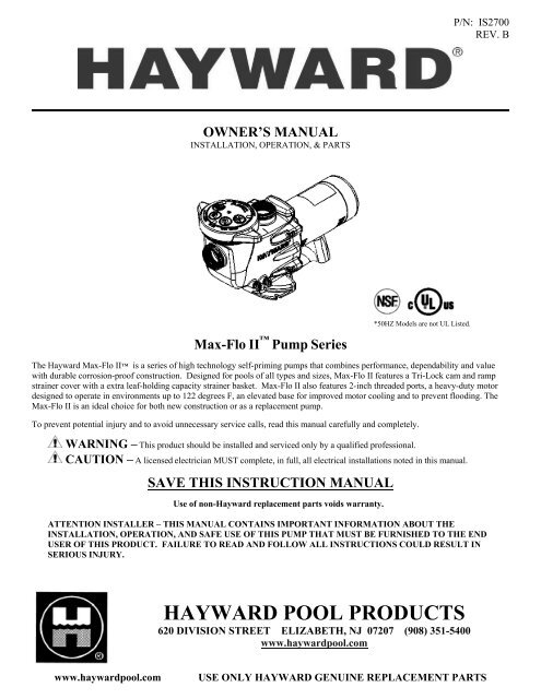
<strong>Max</strong>-<strong>Flo</strong> II <strong>Pump</strong> <strong>Series</strong><br />
*50HZ Models are not UL Listed.<br />
The Hayward <strong>Max</strong>-<strong>Flo</strong> II is a series of high technology self-priming pumps that combines performance, dependability and value<br />
with durable corrosion-proof construction. Designed for pools of all types and sizes, <strong>Max</strong>-<strong>Flo</strong> II features a Tri-Lock cam and ramp<br />
strainer cover with a extra leaf-holding capacity strainer basket. <strong>Max</strong>-<strong>Flo</strong> II also features 2-inch threaded ports, a heavy-duty motor<br />
designed to operate in environments up to 122 degrees F, an elevated base for improved motor cooling and to prevent flooding. The<br />
<strong>Max</strong>-<strong>Flo</strong> II is an ideal choice for both new construction or as a replacement pump.<br />
To prevent potential injury and to avoid unnecessary service calls, read this manual carefully and completely.<br />
WARNING – This product should be installed and serviced only by a qualified professional.<br />
CAUTION – A licensed electrician MUST complete, in full, all electrical installations noted in this manual.<br />
SAVE THIS INSTRUCTION MANUAL<br />
Use of non-Hayward replacement parts voids warranty.<br />
ATTENTION INSTALLER – THIS MANUAL CONTAINS IMPORTANT INFORMATION ABOUT THE<br />
INSTALLATION, OPERATION, AND SAFE USE OF THIS PUMP THAT MUST BE FURNISHED TO THE END<br />
USER OF THIS PRODUCT. FAILURE TO READ AND FOLLOW ALL INSTRUCTIONS COULD RESULT IN<br />
SERIOUS INJURY.<br />
HAYWARD POOL PRODUCTS<br />
620 DIVISION STREET ELIZABETH, NJ 07207 (908) 351-5400<br />
www.haywardpool.com<br />
www.haywardpool.com<br />
USE ONLY HAYWARD GENUINE REPLACEMENT PARTS
<strong>Max</strong>-<strong>Flo</strong> II <strong>Series</strong> ____ ____ _____ _ Page 2 of 16<br />
IMPORTANT SAFETY INSTRUCTIONS<br />
Before installing or servicing this electrical equipment, turn power supply OFF.<br />
Basic safety precautions should always be followed, including the following: Failure to follow instructions may<br />
result in injury.<br />
This is the safety-alert symbol. When you see this symbol on your pump or in this manual, look for one of the<br />
following signal words and are alert to the potential for personal injury.<br />
WARNING warns about hazards that could cause serious personal injury, death or major property<br />
damage and if ignored presents a potential hazard.<br />
CAUTION warns about hazards that will or can cause minor or moderate personal injury and/or property<br />
damage and if ignored presents a potential hazard. It can also make consumers aware of actions that are<br />
unpredictable and unsafe.<br />
The NOTICE label indicates special instructions that are important but not related to hazards.<br />
WARNING – Read and follow all instructions in this<br />
owner’s manual and on the equipment. Failure to follow<br />
instructions can cause severe injury and/or death.<br />
WARNING – This product should be installed and serviced only by a qualified professional.<br />
CAUTION – All electrical wiring MUST be in conformance with all applicable local codes, regulations, and the<br />
National Electric Code (NEC).<br />
Use of non-Hayward replacement parts voids warranty.<br />
ATTENTION INSTALLER – THIS MANUAL CONTAINS IMPORTANT INFORMATION ABOUT THE<br />
INSTALLATION, OPERATION, AND SAFE USE OF THIS PUMP THAT MUST BE FURNISHED TO THE END USER<br />
OF THIS PRODUCT. FAILURE TO READ AND FOLLOW ALL INSTRUCTIONS COULD RESULT IN SERIOUS<br />
INJURY.<br />
WARNING – To reduce risk of injury, do not permit children to use or climb on this product. Closely supervise children<br />
at all times. Components such as the filtration system, pumps, and heaters must be positioned to prevent children from using them as a<br />
means of access to the pool.<br />
CAUTION – This pump is intended for use on permanently installed swimming pools and may also be used with hot tubs<br />
and spas if so marked. Do NOT use with storable pools. A permanently installed pool is constructed in or on the ground or in a<br />
building such that it cannot be readily disassembled for storage. A storable pool is constructed so that it is capable of being readily<br />
disassembled for storage and reassembled to its original integrity.<br />
Though this product is designed for outdoor use, it is strongly advised to protect the electrical components from the weather. Select a<br />
well-drained area, one that will not flood when it rains. It requires free circulation of air for cooling. Do not install in a damp or nonventilated<br />
location. If installed within an outer enclosure or beneath the skirt of a hot tub or spa, adequate ventilation and free circulation<br />
of air must be provided to prevent overheating of the motor.<br />
WARNING – <strong>Pool</strong> and spa components have a finite life. All components should be inspected frequently and replaced at<br />
least every ten years, or if found to be damaged, broken, cracked, missing, or not securely attached.<br />
www.haywardpool.com<br />
USE ONLY HAYWARD GENUINE REPLACEMENT PARTS
<strong>Max</strong>-<strong>Flo</strong> II <strong>Series</strong> _____ _____ _____ _____ ___________________Page 3 of 16<br />
WARNING – Risk of Electric Shock. All electrical wiring MUST be in conformance with all<br />
applicable local codes, regulations, and the National Electric Code (NEC). Hazardous voltage can shock,<br />
burn, and cause death or serious property damage. To reduce the risk of electric shock, do NOT use an<br />
extension cord to connect unit to electric supply. Provide a properly located electrical receptacle. Before<br />
working on pump or motor, turn off power supply to the pump.<br />
WARNING – To reduce the risk of electric shock replace damaged wiring immediately. Locate conduit to prevent abuse<br />
from lawn mowers, hedge trimmers and other equipment.<br />
WARNING – It is recommended to install a Ground Fault Circuit Interrupter (GFCI) in the circuit, however, all<br />
electrical wiring MUST be in conformance with all applicable local codes, regulations, and the National Electric Code (NEC).<br />
WARNING – Failure to bond pump to pool structure will increase risk for electrocution and could result in injury or<br />
death. To reduce the risk of electric shock, see installation instructions and consult a professional electrician on how to bond pump.<br />
Also, contact a licensed electrician for information on local electrical codes for bonding requirements.<br />
Notes to the electrician:<br />
Use a solid copper conductor, size 8 or larger. Run a continuous wire from external bonding lug to reinforcing rod or mesh. Connect<br />
a No. 8 AWG (8.4 mm 2 ) solid copper bonding wire to the pressure wire connector provided on the motor housing and to all metal<br />
parts of swimming pool, spa, or hot tub, and to all electrical equipment, metal piping (except gas piping), and conduit within 5 ft. (1.5<br />
m) of inside walls of swimming pool, spa, or hot tub. IMPORTANT - Reference NEC codes for all wiring standards including, but<br />
not limited to, grounding, bonding and other general wiring procedures.<br />
WARNING – Suction Entrapment Hazard.<br />
Suction in suction outlets and/or suction outlet covers, which are damaged, broken, cracked, missing, or<br />
unsecured cause severe injury and/or death due to the following entrapment hazards:<br />
Hair Entrapment- Hair can become entangled in suction outlet cover.<br />
Limb Entrapment- A limb inserted into an opening of a suction outlet sump or suction outlet cover that is<br />
damaged, broken, cracked, missing, or not securely attached can result in a mechanical bind or swelling of the<br />
limb.<br />
Body Suction Entrapment- A pressure applied to a large portion of the body or limbs can result in an entrapment.<br />
Evisceration/ Disembowelment- A negative pressure applied directly to the intestines through an unprotected suction outlet<br />
sump or suction outlet cover which is damaged, broken, cracked, missing, or unsecured can result in<br />
evisceration/disembowelment.<br />
Mechanical Entrapment- There is potential for jewelry, swimsuits, hair decorations, fingers, toes, or knuckles to be caught<br />
in an opening of a suction outlet cover resulting in mechanical entrapment.<br />
WARNING - To Reduce the risk of Entrapment Hazards:<br />
- When outlets are small enough to be blocked by a person, a minimum of two functioning<br />
suction outlets per pump must be installed. Suction outlets in the same plane (i.e. floor or wall),<br />
must be installed a minimum of three feet (3’) [0.91 meter] apart, as measured from near point<br />
to near point.<br />
- Dual suction fittings shall be placed in such locations and distances to avoid “dual blockage”<br />
by a user.<br />
- Dual suction fittings shall not be located on seating areas or on the backrest for such seating<br />
areas.<br />
- The maximum system flow rate shall not exceed the values shown in the “Pipe Sizing Chart” found at the bottom of page 5<br />
of this manual.<br />
- Never use pool or spa if any suction outlet component is damaged, broken, cracked, missing, or not securely attached.<br />
- Replace damaged, broken, cracked, missing, or not securely attached suction outlet components immediately.<br />
- In addition to two or more suction outlets per pump installed in accordance with latest IAF (formerly NSPI) standards and<br />
CPSC guidelines, follow all national, state, and local codes applicable.<br />
- Installation of a vacuum release or vent system, which relieves entrapping suction, is recommended.<br />
www.haywardpool.com<br />
USE ONLY HAYWARD GENUINE REPLACEMENT PARTS
<strong>Max</strong>-<strong>Flo</strong> II <strong>Pump</strong> <strong>Series</strong> __________ _____ ________________________ Page 4 of 16<br />
WARNING – Hazardous Pressure. <strong>Pool</strong> and spa water circulation systems operate under<br />
hazardous pressure during start-up, normal operation, and after pump shut-off. Stand clear of circulation<br />
system equipment during pump start-up. Failure to follow safety and operation instructions could result in<br />
violent separation of the pump housing and cover due to pressure in the system, which could cause property<br />
damage, severe personal injury, or death. Before servicing pool and spa water circulation system, all<br />
system and pump controls must be in off position and filter manual air relief valve must be in open<br />
position. Before starting system pump, all system valves must be set in a position to allow system water to<br />
return back to the pool. Do not change filter control valve position while system pump is running. Before<br />
starting system pump, fully open filter manual air relief valve. Do not close filter manual air relief valve until a steady stream of water<br />
(not air or air and water) is discharged. All suction and discharge valves MUST be OPEN when starting the circulation system.<br />
Failure to do so could result in severe personal injury and/or property damage.<br />
WARNING – Separation Hazard. Failure to follow safety and operation instructions could<br />
result in violent separation of pump components. Strainer cover must be properly secured to pump housing<br />
with strainer cover lock ring. Before servicing pool and spa circulation system, all system and pump<br />
controls must be in off position and filter manual air relief valve must be in open position. Do not operate<br />
pool and spa circulation system if a system component is not assembled properly, damaged, or missing. Do<br />
not operate pool and spa circulation system unless filter air relief valve body is in locked position in filter<br />
upper body. All suction and discharge valves MUST be OPEN when starting the circulation system.<br />
Failure to do so could result in severe personal injury and/or property damage.<br />
WARNING – Never operate or test the circulation system at more than 50 psi.<br />
WARNING – Fire and burn hazard. Motors operate at high temperatures and if they are not properly isolated from<br />
any flammable structures or foreign debris they can cause fires, which may cause severe personal injury or death. It is also necessary<br />
to allow the motor to cool for at least 20 minutes prior to maintenance to minimize the risk for burns.<br />
WARNING – Failure to install according to all defined instructions may result in severe personal injury or death.<br />
General Information<br />
Introduction<br />
This manual contains information for the proper installation and operation of the Hayward <strong>Max</strong>-<strong>Flo</strong> II TM <strong>Series</strong>. The<br />
instructions in this manual MUST be followed precisely. Failure to install according to defined instructions will void<br />
warranty.<br />
Product Features & Benefits<br />
• Self-priming.<br />
• Tri-Lock cam and ramp strainer cover are designed to seal with less than quarter turn.<br />
• Clear strainer cover lets you see when the basket needs cleaning. Pressure testable to 50 psi<br />
MAXIMUM.<br />
• Large leaf holding capacity strainer basket extends time between cleanings.<br />
• Heavy-duty, high performance motor is designed to operate in environments up to 122° F.<br />
• Elevated base insures better air circulation for cooler running and prevents flooding.<br />
• All components molded of corrosion-proof reinforced engineered plastic for extra durability and long<br />
life.<br />
• Service-Ease Design provides easy access to all internal components by just removing 4 bolts.<br />
www.haywardpool.com<br />
USE ONLY HAYWARD GENUINE REPLACEMENT PARTS
<strong>Max</strong>-<strong>Flo</strong> II <strong>Series</strong>__________ _____ ________________________ ______Page 5 of 16<br />
Product Specifications<br />
Single Speed<br />
HP Dimension "A"<br />
0.75 10.8"<br />
1 11.3"<br />
1.5 12.4"<br />
2 12.5"<br />
Dual Speed<br />
HP Dimension "A"<br />
1 12.0"<br />
1.5 12.5"<br />
2 13.0"<br />
Installation Instructions<br />
WARNING – This product should be installed and serviced only by a qualified professional.<br />
<strong>Pump</strong> Location<br />
Locate pump as close to pool as practical and run suction lines as direct as possible to reduce friction<br />
loss. Suction lines should have continuous slope upward from lowest point in line. Joints must be tight<br />
(but not over-tightened). Suction line diameter must equal or be larger than the discharge line diameter.<br />
Though the pump is designed for outdoor use, it is strongly advised to protect the electrical components<br />
from the weather. Select a well-drained area, one that will not flood when it rains. Do NOT install pump in a damp or<br />
non-ventilated location. Keep motor clean. <strong>Pump</strong> motors require free circulation of air for cooling.<br />
<strong>Pump</strong> Mounting<br />
Install pump on a firm, level base or pad to meet all local and national codes. Fasten pump to base or pad with screws or<br />
bolts to further reduce vibration and stress on pipe or hose joints. The base MUST be solid, level, rigid, and vibration free.<br />
<strong>Pump</strong> mount must:<br />
• Allow pump inlet height to be as close to water level as possible.<br />
• Allow use of short, direct suction pipe (to reduce friction losses).<br />
• Allow for gate valves in suction and discharge piping.<br />
• Be protected from excess moisture and flooding.<br />
• Allow adequate access for servicing pump and piping.<br />
IMPORTANT NOTES – No system should allow any higher than 8-ft/sec [2.44 meters/sec]<br />
water velocity. It is recommended that a minimum length of piping (L as shown to the right), equivalent<br />
to 5 pipe diameters, be used between the pump suction inlet and any plumbing fittings.<br />
Pipe Sizing Chart<br />
MAXIMUM RECOMMENDED SYSTEM FLOW RATE BY PIPE SIZE<br />
Pipe Size <strong>Flo</strong>w rate Water Velocity Pipe Size <strong>Flo</strong>w rate Water Velocity<br />
[mm] GPM [Liter/Min] ft/sec [meters/sec] [mm] GPM [Liter/Min] ft/sec [meters/sec]<br />
1 ½” 50.76 8 2 ½” 119.40 8<br />
[50] [192] [2.44] [75] [452] [2.44]<br />
2” 83.65 8 3” 184.32 8<br />
[63] [317] [2.44] [90] [698] [2.44]<br />
www.haywardpool.com<br />
USE ONLY HAYWARD GENUINE REPLACEMENT PARTS
<strong>Max</strong>-<strong>Flo</strong> II <strong>Series</strong> __________ _____ ______________________ Page 6 of 16<br />
<strong>Pump</strong> Mounting (cont’d)<br />
WARNING – Hazardous Pressure. <strong>Pump</strong>s, filters, and other equipment/ components of a<br />
swimming pool filtration system operate under pressure. Incorrectly installed and/or improperly tested<br />
filtration equipment and/or components may fail resulting in injury and/or property damage.<br />
Plumbing<br />
Use Teflon tape to seal threaded connections on molded plastic components. All plastic fittings must be new or thoroughly<br />
cleaned before use. NOTE - Do NOT use Plumber’s Pipe Dope as it may cause cracking of the plastic components.<br />
When applying Teflon tape to plastic threads, wrap the entire threaded portion of the male fitting with one to two layers of<br />
tape. Wind the tape clockwise as you face the open end of the fitting, beginning at the end of the fitting. The pump suction<br />
and outlet ports have molded-in thread stops. Do NOT attempt to force hose connector fitting past this stop. It is only<br />
necessary to tighten fittings enough to prevent leakage. Tighten fitting by hand and then use a tool to engage fitting an<br />
additional 1 ½ turns. Use care when using Teflon tape as friction is reduced considerably; do NOT over-tighten fitting or<br />
you may cause damage. If leaks occur, remove connector, clean off old Teflon tape, re-wrap with one to two additional<br />
layers of Teflon tape, and re-install connector.<br />
Fittings<br />
Fittings restrict flow. For better efficiency, use the fewest possible fittings (but at least two suction outlets). Avoid fittings<br />
that could cause an air trap. <strong>Pool</strong> and spa fittings MUST conform to the International Association of Plumbing and<br />
Mechanical Officials (IAPMO) standards. Use a non-entrapping suction fitting in pool (multiple drains) or double suction<br />
(skimmer and main drain).<br />
Electrical<br />
WARNING – All electrical wiring MUST be in conformance with all applicable local codes,<br />
regulations, and the National Electric Code (NEC). Ground and bond motor before connecting to<br />
electrical power supply. Failure to ground and bond pump motor can cause serious or fatal electrical<br />
shock hazard. Do NOT ground to a gas supply line. To avoid dangerous or fatal electrical shock, turn<br />
OFF power to motor before working on electrical connections. Fire Hazard - match supply voltage<br />
to motor nameplate voltage. Insure that the electrical supply available agrees with the motor’s<br />
voltage, phase, and cycle, and that the wire size is adequate for the HP (kW) rating and distance from<br />
the power source. Use copper conductors only.<br />
www.haywardpool.com<br />
USE ONLY HAYWARD GENUINE REPLACEMENT PARTS
<strong>Max</strong>-<strong>Flo</strong> II <strong>Series</strong> _ _________ _____ ________________________ Page 7 of 16<br />
Electrical (cont’d.)<br />
Voltage<br />
Voltage at motor MUST NOT be more than 10% above or below motor name plate rated voltage, or<br />
motor may overheat, causing overload tripping and reduced component life. If voltage is less than 90% or<br />
more than 110% of rated voltage when motor is running at full load, consult power company.<br />
Grounding And Bonding<br />
Install, ground, bond, and wire motor in accordance with local or national electrical code requirements.<br />
Permanently ground motor. Use green ground terminal provided under motor canopy or access place; use size and<br />
type wire required by code. Connect motor ground terminal to electrical service ground.<br />
Bond motor to pool structure. Bonding will connect all metal parts within and around the pool with a continuous<br />
wire. Bonding reduces the risk of a current passing between bonded metal objects, which could potentially cause<br />
electrical shock if grounded or shorted. Reference NEC codes for all wiring standards including, but not limited<br />
to, grounding, bonding and general wiring procedures.<br />
Use a solid copper conductor, size 8 or larger. Run wire from external bonding lug to reinforcing rod or mesh.<br />
Connect a No. 8 AWG (8.4 mm 2 ) solid copper bonding wire to the pressure wire connector provided on the motor<br />
housing and to all metal parts of swimming pool, spa, or hot tub, and to all electrical equipment, metal piping<br />
(except gas piping), and conduit within 5 ft. (1.5 m) of inside walls of swimming pool, spa, or hot tub.<br />
Wiring<br />
WARNING – All electrical wiring MUST be in conformance with all applicable local codes, regulations,<br />
and the National Electric Code (NEC).<br />
<strong>Pump</strong> MUST be permanently connected to circuit. If other lights or appliances are also on the same circuit, be sure<br />
to add their amp loads before calculating wire and circuit breaker sizes. Use the load circuit breaker as the Master<br />
On-Off switch.<br />
Start-Up & Operation<br />
Prior to Start-Up<br />
NOTE - If it is necessary to perform a pressure test, prior to initial use to ensure pump is functioning properly, then the<br />
following criteria should be maintained for this test:<br />
1. Have a professional perform this test.<br />
2. Ensure all pump and system components are sealed properly to prevent leaks.<br />
3. Remove any trapped air in the system by fully opening filter manual air relief valve until a<br />
steady stream of water (not air or air and water mix) is discharged from the valve.<br />
4. Allow no more than 50 psi (345 kPa) at a water temperature no higher than 100° F (38° C).<br />
5. Run pressure test for no longer than 24 hours. Immediately inspect all parts to verify they are<br />
intact and functioning properly.<br />
WARNING – If pump is being pressure tested (50 PSI MAXIMUM), be sure pressure<br />
has been relieved prior to removing cover.<br />
WARNING – All suction and discharge valves MUST be OPEN, as well as filter air relief<br />
valve (if available) on filter, prior to starting the circulating pump system. Failure to do so could result in<br />
severe personal injury.<br />
www.haywardpool.com<br />
USE ONLY HAYWARD GENUINE REPLACEMENT PARTS
<strong>Max</strong>-<strong>Flo</strong> II <strong>Series</strong> __________________ ___ _________________________ Page 8 of 16<br />
Starting/Priming the <strong>Pump</strong><br />
• Release all pressure from filter, pump, and piping system. See filter owner’s manual.<br />
WARNING – Return to filter to close the manual air relief valve when a steady stream of water (not air or air<br />
and water) is discharged from the valve. Failure to do so could result in personal injury or death.<br />
• If water source is higher than the pump, pump will prime itself when suction and outlet valves are opened. If water<br />
source is lower than the pump, unscrew and remove strainer cover; fill strainer housing with water.<br />
ATTENTION- NEVER OPERATE THE PUMP WITHOUT WATER. Water acts as a coolant and<br />
lubricant for the mechanical shaft seal. NEVER run the pump dry. Running the pump dry may damage seals,<br />
causing leakage, flooding and voids the warranty. Strainer housing must be filled prior to starting.<br />
• Clean and lubricate strainer cover O-ring with "Jack's 327" each time it is removed. Inspect O-ring and re-install on<br />
strainer cover.<br />
• Replace strainer cover on strainer housing; turn clockwise to tighten cover.<br />
NOTE - Tighten strainer cover lock ring by hand only (no wrenches).<br />
• Verify that there are no leaks from the pump or filter. If leakage occurs DO NOT start pump. If no leakage occurs,<br />
stand at least 10 feet from pump and/or filter and proceed with next step.<br />
• <strong>Pump</strong> is self-priming using 1 ½” pipe. Turn on power and wait for pump to prime, which may take up to five (5)<br />
minutes. Priming time will depend on vertical length of suction lift and horizontal length of suction pipe. If pump<br />
does NOT prime within five minutes, stop motor and determine cause. Be sure all suction and discharge valves are<br />
open when pump is running. See Troubleshooting Guide.<br />
ATTENTION – Wait five (5) seconds before re-starting pump after stopping the pump. Failure to do so may<br />
cause reverse rotation of motor and consequent serious pump damage.<br />
Close filter manual air relief valve after pump is primed.<br />
Maintenance<br />
• Clean strainer basket regularly. Do NOT strike basket to clean. Inspect strainer cover gasket regularly and replace as<br />
necessary.<br />
• Hayward pumps have self-lubricating motor bearings and shaft seals. No lubrication is necessary.<br />
• Keep motor clean. Insure air vents are free from obstruction to avoid damage. Do NOT use water to hose off motor.<br />
• Occasionally, shaft seals must be replaced, due to wear or damage. Replace with genuine Hayward seal assembly kit.<br />
See “Shaft Seal Change Instructions” in this manual.<br />
Storage/Winterization<br />
WARNING – Separation Hazard. Do not purge the system with compressed air. Purging<br />
the system with compressed air can cause components to explode, with risk of severe injury or death to<br />
anyone nearby. Use only a low pressure (below 5 PSI), high volume blower when air purging the pump,<br />
filter, or piping.<br />
ATTENTION – Allowing the pump to freeze will void the warranty.<br />
ATTENTION – Use ONLY propylene glycol as antifreeze in your pool/spa system. Propylene glycol is nontoxic<br />
and will not damage plastic system components; other anti-freezes are highly toxic and may damage plastic components<br />
in the system.<br />
Drain all water from pump and piping when expecting freezing temperatures or when storing pump for a long time (see<br />
instructions below).<br />
Keep motor dry and covered during storage. To avoid condensation/corrosion problems, do NOT cover or wrap pump with<br />
plastic film or bags.<br />
www.haywardpool.com USE ONLY HAYWARD GENUINE REPLACEMENT PARTS
<strong>Max</strong>-<strong>Flo</strong> II <strong>Series</strong> __________________ _____________________________ Page 9 of 16<br />
Storing <strong>Pump</strong> For Winterization<br />
Shaft Seal Change Instructions<br />
WARNING – To avoid dangerous or fatal electrical shock hazard, turn OFF power to motor<br />
before draining pump. Failure to disconnect power may result in serious personal injury or death.<br />
1. Drain water level below all inlets to the pool.<br />
2. Remove drain plugs from bottom of strainer body, and remove strainer cover from strainer housing.<br />
3. Disconnect pump from mounting pad, wiring system (after power has been turned OFF), and piping<br />
system.<br />
4. Once the pump is removed of water, re-install the strainer cover and drain plugs. Store pump in a<br />
dry area.<br />
IMPORTANT SAFETY INSTRUCTIONS<br />
PLEASE READ AND FOLLOW ALL INSTRUCTIONS<br />
When servicing electrical equipment, basic safety precautions should always be observed including the following. Failure to follow<br />
instructions may result in injury.<br />
A. WARNING – To reduce risk of injury, do not permit children to use this product.<br />
B. Disconnect all electrical power service to pump before beginning shaft seal replacement.<br />
C. Only qualified personnel should attempt rotary seal replacement. Contact your local authorized Hayward Dealer or<br />
service center if you have any questions.<br />
Exercise extreme care in handling both the rotating and the stationary sections of the two-part replacement seal. Foreign matter or<br />
improper handling will easily scratch the graphite and ceramic sealing surfaces.<br />
Removing the Motor Assembly (See Parts Diagram on page 11 of this manual for pump component locations.)<br />
1. Remove the four (4) 5/16" x 1 3/4" hex head bolts (item #6) which hold the motor assembly to the<br />
pump/strainer housing (item #4), using a ½” wrench or socket.<br />
2. Slide the motor assembly out of the pump/strainer housing (item #4), exposing the diffuser(item #9). Remove<br />
the two diffuser screws (item #7) and pull the diffuser off of the seal plate (item #13) to expose the impeller<br />
(item #10).<br />
Removing the Impeller (See Parts Diagram on page 11 of this manual for pump component locations.)<br />
3. Remove the motor end cover/canopy by removing the two (2) screws and pulling off the cap/canopy away from<br />
the motor.<br />
4. To prevent motor shaft from turning, carefully slide a 7/16" open-end wrench between the capacitor and the<br />
centrifugal switch (the wrench fits over the two (2) flats on the motor shaft).<br />
5. Rotate the impeller (item #10) counterclockwise and remove. The spring portion of the seal assembly (item<br />
#12) is now exposed. Note carefully the position of the spring seal, and remove it. NOTE - Replace motor<br />
cover to protect delicate motor parts.<br />
Removing the Ceramic Seat (See Parts Diagram on page 11 of this manual for pump component locations.)<br />
6. Remove the seal plate (item #13) from the motor by removing the four (4) 3/8” x 1” (item #14) that secure it to<br />
the motor, using a 9/16” wrench or socket. Remove the motor support base (item #15) from the seal plate (item<br />
#13) by removing the base screw (item #7) with a Phillips head screwdriver.<br />
7. Press the ceramic seat with rubber cup out of the seal plate. If tight, use a small screwdriver to tap seal out.<br />
STOP - Clean all recesses & parts to be reassembled. Inspect gaskets & replace if necessary.<br />
Seal Installation (See Parts Diagram on page 11 of this manual for pump component locations.)<br />
8. Clean and lightly lubricate the motor shaft and seal recess in the seal plate (item #13) with a dilute solution of<br />
non-granulated liquid-type soap. Gently wipe the polished surface of the ceramic seal with a clean, soft, cotton<br />
cloth. Lubricate the rubber cup on the ceramic seat and press it firmly and evenly into the recess of the seal<br />
plate (item #13) with the polished side of the ceramic facing out.<br />
9. Reassemble the motor to the seal plate (item #13) using the four (4) 3/8” bolts (item #14), and reattach the<br />
motor support base using the base screw (item #7) to the seal plate (item #13).<br />
www.haywardpool.com<br />
USE ONLY HAYWARD GENUINE REPLACEMENT PARTS
<strong>Max</strong>-<strong>Flo</strong> II <strong>Series</strong> __________________ ___________________________ ___Page 10 of 16<br />
10. Gently wipe the black, polished surface of the spring seal assembly with a clean, soft, cotton cloth.<br />
11. Press the spring seal assembly (item #12) onto the motor shaft – black polished surface facing toward the<br />
polished surface of the ceramic seat.<br />
Replacing the Impeller and Diffuser (See Parts Diagram on page 11 of this manual for pump component locations.)<br />
11. Screw the impeller (item#10) onto the motor shaft in a clockwise direction. Tighten snugly by holding motor<br />
shaft with wrench as noted in step #4.<br />
12. Place the diffuser (item #9) over the impeller (item#10) onto the seal plate (item#13), aligning the three (3)<br />
protruding pins with the matching holes in the seal plate (item#13). Note: Arrow on diffuser (item #9) will<br />
face up. Replace two diffuser screws (item #7).<br />
Replacing the Motor Assembly (See Parts Diagram on page 11 of this manual for pump component locations.)<br />
14. Re-attach motor end cover/canopy by using the two (2) hex shaped screws. Slide the motor assembly with the<br />
diffuser (item#9) in place, into pump/strainer housing (item#4), being careful not to disturb the diffuser gasket<br />
(item#8).<br />
15. Re-attach assembly to pump/strainer housing (item#4) using the four (4) 5/16”" x 1 3/4" hex head bolts. (Be<br />
sure housing gasket (item#11) is in place, and lubricated. Replace if damaged). Tighten alternately and evenly<br />
to 185 in-lbs using torque pattern in diagram 1 at bottom of this page.<br />
Diagram 1<br />
www.haywardpool.com<br />
USE ONLY HAYWARD GENUINE REPLACEMENT PARTS
<strong>Max</strong>-<strong>Flo</strong> II <strong>Series</strong> __________________ ____________________________ Page 11 of 16<br />
Replacement Parts<br />
Parts Diagram<br />
Item #16: Optional with<br />
some models<br />
SEE PARTS LISTING ON NEXT PAGE<br />
www.haywardpool.com<br />
USE ONLY HAYWARD GENUINE REPLACEMENT PARTS
<strong>Max</strong>-<strong>Flo</strong> II <strong>Series</strong> __________________ ____________________________ Page 12 of 16<br />
Parts Listing<br />
Ref.<br />
No. Part No. Description Ctn. Qty.<br />
1a SPX2700DLS Strainer Cover Kit (Includes Strainer Cover,<br />
Lock-Ring, O-Ring)<br />
10<br />
1b SPX2700DLSB<br />
Strainer Cover Kit for Biguanide Sanitizers<br />
(Includes Strainer Cover, Lock-Ring, O-Ring)<br />
NOT Pressure Testable<br />
2 SPX2700Z4 Strainer Cover O-Ring 10<br />
3 SPX2700M Strainer Basket 15<br />
4 SPX2700AA <strong>Pump</strong> Strainer Housing , 2”X2” with Drain Plugs,<br />
threaded style, basket and strainer cover kit<br />
1<br />
5 SPX4000FG Drain Plug with O-Ring 10<br />
6 SPX2700ZPAK Hardware Pack (Includes 4 Housing Bolts, Seal- 10<br />
Plate Spacers and Square Nuts<br />
7 SPX2700Z3 Diffuser Screws (3 per) 1<br />
8 SX220Z2 Diffuser O-Ring 10<br />
9 SPX2700B Diffuser, ¾ thru 1 ½ HP 1<br />
SPX2700BE Diffuser, 2 HP 1<br />
10 SPX2700C Impeller for ¾ HP <strong>Max</strong>-Rate <strong>Pump</strong> 10<br />
SPX2707CM Impeller for 1 HP <strong>Max</strong>-Rate <strong>Pump</strong> 10<br />
SPX2710CM Impeller for 1 ½ HP <strong>Max</strong>-Rate <strong>Pump</strong> 10<br />
SPX2715CM Impeller for 2 HP <strong>Max</strong>-Rate <strong>Pump</strong> 10<br />
11 GMX600F Housing O-Ring 10<br />
12 SPX2700SA Shaft Seal Assembly 10<br />
13 SPX2700E Seal Plate 10<br />
14 SPX3200Z5 Motor Bolt 1<br />
15 SPX2700G Motor Support 1<br />
Optional<br />
16 SP2700UNKIT Union Connector Kit (Includes 2 Nuts,<br />
1<br />
Connectors, Gaskets)<br />
Motors<br />
SPX2705Z1M Motor, ¾ HP, Threaded Shaft (Single Phase, 60<br />
Cycle 115V/230V)<br />
1<br />
SPX2707Z1M Motor, 1 HP, Threaded Shaft (Single Phase, 60<br />
Cycle 115/230V)<br />
SPX2710Z1M Motor, 1-1/2 HP, Threaded Shaft (Single Phase,<br />
60 Cycle 115/230V)<br />
SPX2715Z1ME Motor, 2 HP, Threaded Shaft (Single Phase, 60<br />
Cycle 115/230V)<br />
SPX2707Z2M Motor, 1 HP, Two Speed, Threaded Shaft (Single<br />
Phase, 60 Cycle 115/230V)<br />
SPX2710Z2M<br />
SPX2715Z2M<br />
Motor, 1-1/2 HP, Two Speed, Threaded Shaft<br />
(Single Phase, 60 Cycle 115/230V)<br />
Motor, 2 HP, Two Speed, Threaded Shaft (Single<br />
Phase, 60 Cycle 115/230V)<br />
10<br />
1<br />
1<br />
1<br />
1<br />
1<br />
1<br />
www.haywardpool.com<br />
USE ONLY HAYWARD GENUINE REPLACEMENT PARTS
<strong>Max</strong>-<strong>Flo</strong> II <strong>Series</strong> __________________ ____________________________ Page 13 of 16<br />
Troubleshooting<br />
Motor Will NOT Start – Check For:<br />
Make sure the terminal board connections agree with the wiring diagram on motor data plate label. Be sure motor is wired<br />
for available field supply voltage.<br />
1. Improper or loose wiring connections; open switches or relays; tripped circuit breakers, GFCI’s, or blown fuses.<br />
Solution: Check all connections, circuit breakers, and fuses. Reset tripped breakers or replace blown fuses.<br />
2. <strong>Manual</strong>ly check rotation of motor shaft for free movement and lack of obstruction.<br />
Solution: Refer to Steps 4 & 5 of “Shaft Seal Change Instructions” in this manual.<br />
3. If you have a timer, be certain it is working properly. Bypass it if necessary.<br />
Motor Shuts OFF – Check For:<br />
1. Low voltage at motor or power drop (frequently caused by undersized wiring or extension cord use).<br />
Solution: Contact qualified professional to check that the wiring gauge is heavy enough.<br />
NOTE - Your Hayward pump motor is equipped with an “automatic thermal overload protector.” The motor will<br />
automatically shut off if power supply drops before heat damage can build up causing windings to burn out. The “thermal<br />
overload protector” will allow the motor to automatically restart once the motor has cooled. It will continue to cut On/Off<br />
until the problem is corrected. Be sure to correct cause of overheating.<br />
Motor Hums, But Does NOT Start – Check For:<br />
1. Impeller jammed with debris.<br />
Solution: Have a qualified repair professional open the pump and remove the debris.<br />
<strong>Pump</strong> Won't Prime, Check For:<br />
1. Empty pump/strainer housing.<br />
Solution: Make sure pump/strainer housing is filled with water and cover o-ring is clean. Ensure o-ring is properly seated in<br />
the cover o-ring groove. Ensure o-ring is lubricated with “Jack’s 327” and that strainer cover is locked firmly in position.<br />
Lubricant will help to create a tighter seal.<br />
2. Loose connections on suction side.<br />
Solution: Tighten pipe/union connections.<br />
NOTE - Any self-priming pump will not prime if there are suction air leaks. Leaks will result in bubbles emanating from<br />
return fittings on pool wall.<br />
3. Leaking O-ring or packing glands on valves.<br />
Solution: Tighten, repair, or replace valves.<br />
4. Strainer basket or skimmer basket loaded with debris.<br />
Solution: Remove strainer housing cover or skimmer cover, clean basket, and refill strainer housing with water. Tighten<br />
cover.<br />
5. Suction side clogged.<br />
Solution: Contact a qualified repair professional.<br />
Block off to determine if pump will develop a vacuum. You should have 5”-6” of vacuum at the strainer cover (Only your<br />
pool dealer can confirm this with a vacuum gauge). You may be able to check by removing the skimmer basket and<br />
holding your hand over the bottom port with skimmer full and pump running. If no suction is felt, check for line blockage.<br />
a. If pump develops a vacuum, check for blocked suction line or dirty strainer basket. An air leak in the suction<br />
piping may be the cause.<br />
b. If pump does not develop a vacuum and pump has sufficient “priming water”:<br />
i. Re-check strainer housing cover and all threaded connections for suction leaks. Check if all system<br />
hose clamps are tight.<br />
ii. Check voltage to ensure that the motor is rotating at full RPM’s.<br />
iii. Open housing cover and check for clogging or obstruction in suction. Check impeller for debris.<br />
iv. Remove and replace shaft seal only if it is leaking.<br />
Low <strong>Flo</strong>w – Generally, Check For:<br />
1. Clogged or restricted strainer or suction line.<br />
Solution: Contact a qualified repair professional.<br />
www.haywardpool.com<br />
USE ONLY HAYWARD GENUINE REPLACEMENT PARTS
<strong>Max</strong>-<strong>Flo</strong> II <strong>Series</strong> __________________ ___________________________ _ Page 14 of 16<br />
Low <strong>Flo</strong>w – Generally, Check For: (cont’d.)<br />
2. Undersized pool piping.<br />
Solution: Correct piping size.<br />
3. Plugged or restricted discharge line of filter, valve partially closed (high gauge reading).<br />
Solution: Sand filters – backwash as per manufacturer’s instructions; D.E. filters – backwash as per manufacturer’s<br />
instructions; Cartridge filters – clean or replace cartridge.<br />
4. Air leak in suction (bubbles issuing from return fittings).<br />
Solution: Re-tighten using Teflon tape.<br />
5. Plugged, restricted, or damaged impeller.<br />
Solution: Replace including new seal assembly.<br />
Noisy <strong>Pump</strong> – Check For:<br />
1. Air leak in suction piping, cavitations caused by restricted or undersized suction line or leak at any joint, low water level<br />
in pool, and unrestricted discharge return lines.<br />
Solution: Correct suction condition or throttle return lines, if practical. Holding hand over return fitting will sometimes<br />
prove this point or putting in a smaller eyeball fitting.<br />
2. Vibration due to improper mounting, etc.<br />
Solution: Mount the pump on a level surface and secure the pump to the equipment pad.<br />
3. Foreign matter in pump housing. Loose stones/debris hitting impeller could be cause.<br />
Solution: Clean the pump housing.<br />
4. Motor bearings noisy from normal wear, rust, overheating, or concentration of chemicals causing seal damage which will<br />
allow chlorinated water to seep into bearings wiping out the grease causing bearing to whine.<br />
Solution: All seal leaks should be replaced at once.<br />
© Hayward <strong>Pool</strong> Products, 2005<br />
All rights reserved.<br />
www.haywardpool.com<br />
USE ONLY HAYWARD GENUINE REPLACEMENT PARTS
<strong>Max</strong>-<strong>Flo</strong> II <strong>Series</strong> ___ Page 15 of 16<br />
HAYWARD ® LIMITED WARRANTY<br />
This pump was inspected before shipment from our plant. To original purchasers of this pump, Hayward <strong>Pool</strong><br />
Products, 620 Division Street, Elizabeth, New Jersey, warrants its products free from defects in materials and<br />
workmanship for a period of ONE (1) year from the date of purchase.<br />
Parts which fail or become defective during the warranty period, except as a result of freezing, negligence, improper<br />
installation, use, or care, shall be repaired or replaced, at our option, without charge, within 90 days of the receipt of<br />
defective product, barring unforeseen delays.<br />
To obtain warranty replacements or repair, defective components or parts should be returned, transportation paid, to<br />
the place of purchase, or to the nearest authorized Hayward service center. For further Hayward dealer or service<br />
center information, contact Hayward customer service department. No returns may be made directly to the factory<br />
without the express written authorization of Hayward <strong>Pool</strong> Products.<br />
To original purchasers of this pump, Hayward <strong>Pool</strong> Products warrants its pump housing/strainer to be free from<br />
defects in materials and workmanship for a period of ONE (1) year from the date of purchase.<br />
<strong>Pump</strong> housing/strainers which become defective during the warranty period, except as a result of freezing,<br />
negligence, improper installation, use or care, or as the result of a use in association with an automatic valving<br />
system, shall be repaired, at our option, without charge.<br />
All other conditions and terms of the standard warranty apply.<br />
Hayward shall not be responsible for cartage; removal and/or reinstallation labor or any other such costs incurred in<br />
obtaining warranty replacements.<br />
The Hayward <strong>Pool</strong> Products warranty does not apply to components manufactured by others. For such products, the<br />
warranty established by the respective manufacturer will apply.<br />
Some states do not allow a limitation on how long an implied warranty lasts, or the exclusion or limitation of<br />
incidental or consequential damages, so the above limitation or exclusion may not apply to you.<br />
This warranty gives you specific legal rights, and you may also have other rights, which vary from state to state.<br />
Hayward <strong>Pool</strong> Products<br />
620 Division Street<br />
*Supersedes all previous publications. Elizabeth, NJ 07207<br />
▲Retain this Warranty Certificate (upper portion) in a safe and convenient location for your records.<br />
▼DETACH HERE: Register online at www.hayward pool.com or fill out bottom portion completely and mail within 10 days of purchase/installation.<br />
------------------------------------------------------------------------------------------------------------<br />
Mail to: Hayward <strong>Pool</strong> Products, 620 Division Street, Elizabeth, NJ 07207, Attn: Warranty Dept.<br />
Warranty Registration Card<br />
Name__________________________________________________ Years pool has been in service □ less than 1 □ 1-3 □ 3-5 □ 5-10<br />
Address________________________________________________<br />
City______________________ State_________ Zip____________<br />
E-mail Address__________________________________________<br />
Product Purchased ______________________________________<br />
Purchased from:<br />
Company name________________________________________________<br />
Address_______________________________________________________<br />
City__________________________ State_________ Zip_______________<br />
Product Serial No. _______________________________________<br />
Please send me more information on these other<br />
□ New Installation □ Replacement products from Hayward:<br />
Type of In-Ground <strong>Pool</strong>: □ <strong>Pump</strong> □ Filter □ Automatic <strong>Pool</strong> Cleaner □ Light<br />
□ Vinyl □ Fiberglass □ Gunite □ Chlorinator □ Skimmer □ Heater □ Heat <strong>Pump</strong><br />
Size of <strong>Pool</strong>______________________________________<br />
□ Salt/Chlorine Generator<br />
□ Controls<br />
www.haywardpool.com<br />
USE ONLY HAYWARD GENUINE REPLACEMENT PARTS
<strong>Max</strong>-<strong>Flo</strong> II <strong>Series</strong> ___ Page 16 of 16<br />
This Page is Blank<br />
www.haywardpool.com<br />
USE ONLY HAYWARD GENUINE REPLACEMENT PARTS