Hayward Pool Vac XL Owner's Manual - Pool Center
Hayward Pool Vac XL Owner's Manual - Pool Center
Hayward Pool Vac XL Owner's Manual - Pool Center
You also want an ePaper? Increase the reach of your titles
YUMPU automatically turns print PDFs into web optimized ePapers that Google loves.
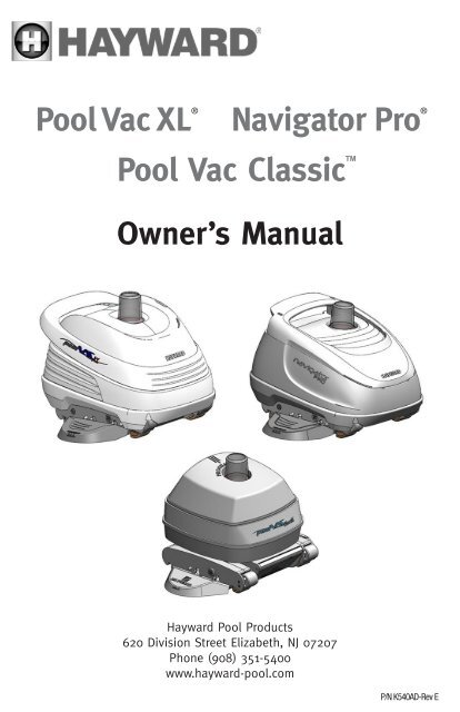
<strong>Pool</strong> <strong>Vac</strong> <strong>XL</strong> ® Navigator Pro ®<br />
<strong>Pool</strong> <strong>Vac</strong> Classic<br />
Owner’s <strong>Manual</strong><br />
<strong>Hayward</strong> <strong>Pool</strong> Products<br />
620 Division Street Elizabeth, NJ 07207<br />
Phone (908) 351-5400<br />
www.hayward-pool.com<br />
P/N K540AD-Rev E
Turbine Suction Cleaner<br />
OWNER’S MANUAL<br />
Congratulations on your purchase of your <strong>Hayward</strong> automatic suction pool cleaning system<br />
from <strong>Hayward</strong>. Your Cleaner is the smart, efficient way to clean your in-ground pool.<br />
<strong>Hayward</strong> Turbine Cleaners are powered by your pool’s filter system and are designed to<br />
work well with most systems. Therefore the performance of the Cleaner in your pool will<br />
be relative to that power source. Because the operation and performance of the Cleaner<br />
are system reliant, there is a remote possibility that a “service call” may be necessary to<br />
complete the proper installation of your Cleaner. Because this is an installation related<br />
call, it will be at the consumer’s expense. Also, one or more of the accessories designed<br />
for the Cleaner, including additional hose sections (if needed), might be applicable to<br />
your installation. Consult your <strong>Hayward</strong> dealer for the price and availability. For Technical<br />
Assistance, call <strong>Hayward</strong> at 908-355-7995 (USA only).<br />
For Your Records<br />
Record the following information for your convienience<br />
1) Purchase Date<br />
2) Serial Number<br />
<strong>Pool</strong> <strong>Vac</strong> <strong>XL</strong><br />
Navigator Pro<br />
LIMITED<br />
WARRANTY<br />
<strong>Pool</strong> <strong>Vac</strong><br />
Classic<br />
LIMITED<br />
WARRANTY<br />
Note<br />
<strong>Hayward</strong> Turbine Cleaners should not be used to clean the pool for spring start-up<br />
unless the conditions noted in Step 1 are met. On those occasions, where your pool is<br />
subjected to an abnormal debris load, maintenance steps should be taken to return the<br />
pool to “pre-installations” condition.
Installation<br />
INSTALLING YOUR HAYWARD CLEANER IS SIMPLE...<br />
To prepare your pool for installation, please follow the easy steps listed below. After<br />
reading these instructions, the “How To” installation DVD (included with <strong>Pool</strong> <strong>Vac</strong> <strong>XL</strong> &<br />
Navigator Pro only) will walk you through the installation step-by-step, and it will also give<br />
you some maintenance and trouble-shooting hints. These instructions apply to all <strong>Hayward</strong><br />
Turbine Cleaner models.<br />
Step 1<br />
Check the pool and remove any large objects that might interfere with the cleaner’s<br />
operation. Check to see that the water level is at the recommended level. Check the water<br />
chemistry. Make sure that the water is properly balanced and that the pool is free from<br />
algae. Algae can adversely affect the operation of the Cleaner and its performance.<br />
Step 2<br />
Clean or backwash the filter, and clean the hair and lint prior to installing the Cleaner.<br />
Following the installation of your Cleaner, clean the system at regular intervals according to<br />
individual pool conditions.<br />
Step 3<br />
There are connector hoses (9 with PV <strong>XL</strong> & NAV PRO, 7 with PV Classic) and one leader<br />
hose with a hose cuff are included. The hose cuff has a red sticker attached to it that reads<br />
“REMOVE LABEL AND CONNECT TO CLEANER”.<br />
Connect the exclusive <strong>Hayward</strong> hose sections together by pushing and twisting the tapered<br />
male connector end of each hose firmly into the open female end of the adjacent hose (see<br />
Figure 1). Depending on the size and shape of your pool, all hose sections might not be<br />
used. However, the leader hose must be used or your Cleaner will not operate properly. It is<br />
not necessary to “Bottom Out” the connections, but they must be tight enough to prevent<br />
any air leaks. Wetting the hose ends will make it easier to connect the hose sections.<br />
1
Installation<br />
INSTALLING YOUR HAYWARD CLEANER IS SIMPLE...<br />
Step 4<br />
The hose should reach from the skimmer or <strong>Hayward</strong> <strong>Vac</strong> Lock® to the furthest point in<br />
the pool, plus two (2) extra hose sections. (The length of each hose section is four feet.)<br />
This extra length is absolutely necessary for proper operation of your <strong>Hayward</strong> Cleaner. If<br />
the hose is not long enough, it will be necessary to purchase additional hose sections from<br />
your <strong>Hayward</strong> dealer. The hose length supplied has been determined to be sufficient for<br />
the class and size of pools for which each type of cleaner is sold – 40 feet for PV <strong>XL</strong> & NAV<br />
Pro, 32 feet for PV Classic. If your hose requirement is more than this, you must obtain<br />
additional hose sections for your cleaner to work properly. After the correct hose length has<br />
been assembled, fill hose completely with water. Insert Flow Gauge into the leader hose,<br />
then attach the C-Clip of the gauge onto the first hose section. Make sure the Flow Gauge<br />
is under water. (see Figure 2)<br />
Step 5<br />
Turn the filter system on and allow it to run long<br />
enough to eliminate any air in the system. Connect the<br />
V093C Skimmer Cone adapter to the tapered male end of<br />
the vacuum hose if you are connecting the hose to your<br />
skimmer. Then, insert the cone into the suction port of<br />
the skimmer (see Figure 3) or, if you are using a<br />
<strong>Hayward</strong> <strong>Vac</strong> Lock, insert the hose end directly<br />
into the <strong>Vac</strong> Lock without using the cone. (Refer<br />
to Important Tips for more specific skimmer<br />
information.)<br />
2
Installation<br />
INSTALLING YOUR HAYWARD CLEANER IS SIMPLE...<br />
Step 6<br />
Check the water flow reading on the Flow Gauge. (Refer to Step 4, Figure 2). The black disk<br />
should be in the box between the “MIN” and “MAX” markings. If the setting is higher than<br />
required with the black disk outside of the box on the “MAX” side and you have connected<br />
your hose to the skimmer, it will be necessary to reduce the vacuum/water flow by using<br />
a valve or valves in the filter system, or the <strong>Hayward</strong> V094 Regulator Valve or an optional<br />
<strong>Hayward</strong> Automatic Skimmer <strong>Vac</strong>uum Plate designed to adjust vacuum/water flow. To install<br />
the V094 Regulator Valve, turn the filter system off, remove the hose from the V093C<br />
Skimmer Cone, and after closing the Regulator Valve (Rotate the blue collar clockwise until<br />
tight), insert the Valve into the Skimmer Cone, and insert the hose end into the Valve (see<br />
Figure 4).<br />
Turn the filter system on and allow it to run long enough to eliminate any air in the system.<br />
Turn the blue collar counter clockwise until proper reading appears on the gauge. If a<br />
<strong>Hayward</strong> Skimmer <strong>Vac</strong>uum Plate is to be used, follow the installation instructions included<br />
with the Skimmer <strong>Vac</strong>uum Plate.<br />
3
Note<br />
Installation<br />
INSTALLING YOUR HAYWARD CLEANER IS SIMPLE...<br />
The V094 Regulator Valve and the <strong>Hayward</strong> Skimmer <strong>Vac</strong>uum Plate can only be used to<br />
LOWER an initial vacuum reading that is TOO HIGH. The Regulator Valve and the Skimmer<br />
<strong>Vac</strong>uum Plate cannot be used to INCREASE the initial vacuum reading. An initial reading<br />
that is too low to meet the water flow setting necessary to operate the cleaner is indicative<br />
of a system problem, and not a problem with the cleaner.<br />
Contact your Authorized <strong>Hayward</strong> Dealer for assistance.<br />
If you have connected your hose to the <strong>Hayward</strong> <strong>Vac</strong> Lock, it will be necessary to adjust<br />
the vacuum/water flow using the 3-way valve at the filter system. The handle on the valve<br />
should be turned so that the Flow Gauge which is installed in the Cleaner hose reads<br />
properly (refer to Figure 2). After the 3-way valve has been properly adjusted, the 3-way<br />
valve should be marked so that the water flow can be adjusted by referring to the valve<br />
handle mark, rather than reinstalling the Flow Gauge in the hose each time an adjustment<br />
is necessary.<br />
Step 7<br />
Remove the Flow Gauge from the hose and keep it handy. You will want to use the Flow<br />
Gauge to check the Cleaner’s operation from time to time if the Cleaner is connected to<br />
your skimmer. If you are using a <strong>Hayward</strong> <strong>Vac</strong> Lock, the Flow Gauge will only be necessary<br />
if you neglect to mark the valve gauge, or if replacement of the valve gauge is necessary.<br />
Step 8<br />
Check the rear flap adjuster dial at the left rear of the Cleaner. It should be set at position<br />
number II which is the middle position (see Figure 5). Submerge the Cleaner into the water<br />
to remove all of the entrapped air. When escaping air bubbles cease, you are ready to<br />
connect the hose.<br />
Connect the hose cuff of the leader hose to the Cleaner and submerge the hose to remove<br />
all air as when vacuuming the pool with a standard hand-vacuum (see Figure 6).<br />
Do not use the return line/inlet water to “sink” the Cleaner hose, as this will force air into<br />
the cleaner head, and possibly cause performance problems.<br />
4
Installation<br />
INSTALLING YOUR HAYWARD CLEANER IS SIMPLE...<br />
Step 9<br />
Observe your Cleaner in operation, and make sure that the return line flow is not affecting<br />
the Cleaner’s programmed steering and preventing the Cleaner from covering the entire<br />
pool. If the cleaner hose is being pushed across the surface of the pool, it will be necessary<br />
to redirect the return line water flow downward. This is to allow the Cleaner to move its<br />
programmed cleaning pattern.<br />
Step 10<br />
Observing the Cleaner in operation, it should move about the pool without spending an<br />
excessive amount of time against the steps or other obstructions (vertical walls, ladders,<br />
etc.) If the Cleaner seems to get “hung up,” turn the rear flap adjuster to position I (see<br />
Figure 5).<br />
Step 11<br />
Your Cleaner will climb the vertical walls in concrete and fiberglass swimming pools if there<br />
is at least a seven inch (7") radius where the walls and floor meet. The Cleaner’s wall<br />
climbing is governed by the programmed steering and therefore it will not climb the wall<br />
each time it comes in contact with a wall. When the Cleaner does start up a wall, it will not<br />
always go all the way up the wall. If the Cleaner does not seem to be “sticking” to the wall,<br />
turn the rear flap adjuster to position III (see Figure 5). If the Cleaner climbs to the water’s<br />
surface and sucks air, turn the rear flap adjuster to Position I (see Figure 5). If the cleaner<br />
continues to climb too high, reduce the water flow until proper operation is achieved.<br />
Approximately ninety percent (90%) of the dirt in a concrete pool will be on the floor of<br />
the pool. Approximately ten percent (10%) of the dirt will be on the walls. Your Cleaner will<br />
spend its cleaning time accordingly.<br />
5
Turbine Suction Cleaners<br />
IMPORTANT TIPS<br />
<strong>Pool</strong> <strong>Vac</strong> <strong>XL</strong>/Navigator Pro<br />
In one piece fiberglass pools there is very little dirt on the walls, but your Cleaner will still<br />
climb the walls. Due to the shape (severe angles) of most in-ground vinyl liner pools, your<br />
Cleaner’s cleaning is confined to the bottom (both shallow and deep) and the hopper sides.<br />
<strong>Hayward</strong> Turbine Cleaners do not climb the vertical walls of in-ground or on-ground vinyl<br />
liner pools. However, normal dirt and debris do not adhere to these walls.<br />
DO NOT COIL HOSE<br />
When storing your cleaner the hose sections must be stored straight, not coiled. A coiled<br />
hose will create a memory in the hose that will impede the Cleaner’s ability to move<br />
properly in your pool. Coiled hoses are not covered under the <strong>Hayward</strong> warranty. When<br />
removing the Cleaner from your pool, be sure to grasp the cleaner by its handle, not by its<br />
hose, otherwise the Cleaner might be damaged should the hose disconnect from the cleaner.<br />
1. Skimmers come in many configurations and cannot all be described here. Three basic<br />
types are discussed however.<br />
Some skimmers have two (2) holes in the bottom. There might be a valve, float or cover<br />
over the holes. Remove everything in the skimmer, exposing the holes. The rear hole is<br />
usually the suction port. In some cases it will be necessary to use the V094 Regulator Valve<br />
to control water flow through the Cleaner (see Figure 4).<br />
Some skimmers have only one hole in the bottom. This suction port is usually controlled by a<br />
valve at the filter system and most likely will not need a V094 Regulator Valve (see Figure 3).<br />
6
Turbine Suction Cleaners<br />
IMPORTANT TIPS<br />
Some skimmers have a vari-flow or diverter valve in the bottom of the skimmer. This valve<br />
can be turned to regulate skimming and main drain suction. Turn the valve to full skim<br />
and then adjust the Flow Gauge by turning the valve toward main drain suction. Usually<br />
this valve is the same size as the Cleaner’s hose end, and it will therefore be necessary<br />
to purchase a V098 Hose Adapter (see Figure 7). After the proper gauge reading has been<br />
established, the diverter valve will have to be locked in the place with a wedge of some<br />
kind so that it won’t change position with operation of the Cleaner.<br />
2. Periodically check the water flow/vacuum to be sure that your Cleaner is operating as<br />
efficiently as possible. Remember, too much vacuum is just as bad as too little.<br />
3. Periodically check to make sure that the Cleaner hose is securely attached to its suction<br />
source (i.e. Skimmer, Skimmer <strong>Vac</strong> Plate <strong>Vac</strong> Lock, etc.)<br />
4. Disconnect the Cleaner hose from the skimmer/regulator valve, or, if using a “dedicated<br />
line”, turn cleaner valve off prior to “backwashing”, so as not to restrict water flow.<br />
5. Never coil the Cleaner hose. Coiled hose is not covered under the warranty.<br />
6. When the Cleaner is out of the pool, always disconnect the leader hose from the<br />
Cleaner’s head.<br />
7. Always carry your Cleaner by the molded-in handle. Do not carry it by the hose.<br />
8. When swimming in the pool, remove your Cleaner from the water.<br />
9. If you are going to super chlorinate, shock, or add gas chlorine to your pool, make sure<br />
the cleaner and its hose are removed prior to doing so.<br />
CLEANER<br />
7
Turbine Suction Cleaner<br />
MAINTENANCE TIPS<br />
1. Check the condition of the “shoes, wings and flaps” periodically. The shoes and wings<br />
have wear indicators on their sides and should be checked occasionally to determine<br />
if they need replacing. The shoe wear indicator is a line on the side of the shoe that<br />
appears as a difference in texture. When this texture difference is no longer visible at the<br />
bottom of the shoe when viewed from either side, the shoes must be changed (see<br />
Figure 8). Also on the side, the wing wear indicator is a horizontal line which has three<br />
(3) vertical lines above it. When you can no longer see the horizontal line, the wings<br />
must be changed (see Figure 9). The <strong>Hayward</strong> Tune-Up Kit is available from your dealer.<br />
Shoes, wings and flaps may also be purchased separately.<br />
2. SHOE REPLACEMENT:<br />
a) Turn unit upside down.<br />
b) Insert screwdriver between foot and shoe on one of the pads (see Figure 8).<br />
c) Using a lifting motion, remove the shoe from the foot.<br />
d) Dip a new shoe in water and attach the shoe to the foot, making sure to put the small<br />
post into the small hole and the large post into the large hole. These posts and holes<br />
are different sizes to prevent the shoes from being improperly installed.<br />
e) Repeat Steps b,c, and d for each shoe.<br />
GOOD SHOE<br />
WEAR MARK<br />
GOOD SHOE<br />
WEAR MARK<br />
WORN SHOE<br />
.250<br />
WORN SHOE<br />
.250<br />
8
Turbine Suction Cleaner<br />
MAINTENANCE TIPS<br />
3. WING REPLACEMENT:<br />
a) Using a screwdriver, remove the plugs from both pods (see Figure 9).<br />
b) Remove the old wings by bending the wings up toward the sides of the cleaner, and<br />
lift them off their hooks (see Figure 10). If any of the wing hooks are broken, take the<br />
Cleaner to your dealer for pod replacement as the unit will not function properly if the<br />
wings are not properly attached.<br />
c) Replace the wings, making sure that you match the “L” (Left) and “R” (Right) of the pods.<br />
d) Replace the pod plugs and tap them into place with the screwdriver handle.<br />
9
Turbine Suction Cleaner<br />
MAINTENANCE TIPS<br />
4. FLAP REPLACEMENT:<br />
a) Remove the front and rear flaps from your Cleaner by inserting a small screwdriver<br />
between the flap and the lower body near the pivot point of the flaps (see Figure 11).<br />
b) You will notice that your replacement flaps look similar but are marked “Front” and<br />
“Rear” on the flap. Because the springs in the flaps are different, it is absolutely<br />
necessary to install the proper flap in the front and rear of the unit. Failure to do<br />
so will result in unsatisfactory performance of your Cleaner. When installing the front<br />
flap, be sure that the extended leg of the spring is inserted into the notch on the<br />
front of the lower body (see Figure 12). Push the flap in place. You will actually feel<br />
and hear a snap when the flap is in place. Fold the flap in towards the bottom of the<br />
Cleaner. You will feel some resistance at this point (that is normal). As the flap snaps<br />
into its normal position, you will feel the spring action and notice that the front flap is<br />
now in its normal operating position.<br />
When installing the rear flap, the extended leg of the spring must fit against one of the flat<br />
surfaces of the cam (see Figure 12).<br />
10
<strong>Pool</strong> <strong>Vac</strong> <strong>XL</strong><br />
MAINTENANCE TIPS<br />
5. POOL VAC <strong>XL</strong> SKIRT/MID SECTION REPLACEMENT:<br />
Replacement of the <strong>Pool</strong> <strong>Vac</strong> <strong>XL</strong> Skirt/Mid Section is not recommended as DIY repair.<br />
There is strong possibility that the replacement could cause propulsion system issues. It is<br />
strongly suggested that you bring your <strong>Pool</strong> <strong>Vac</strong> <strong>XL</strong> to a HAYWARD dealer for replacement.<br />
Tools required —<br />
#2 Phillips screwdriver<br />
1/8” flat screwdriver<br />
8 7 6<br />
Preliminary steps — Turn off pool pump<br />
Remove <strong>Pool</strong> D <strong>Vac</strong> <strong>XL</strong> from pool<br />
Disconnect suction hose from cleaner<br />
Change out steps —<br />
1<br />
1<br />
2<br />
1. Insert the 1/8” flat screwdriver into each slot in the<br />
handle and pry each cover snap off the<br />
handle.<br />
C<br />
3<br />
2. Using the phillips screwdriver, remove and retain the<br />
four screws holding the Handle onto the Middle Body.<br />
3. Lift the Handle off the Middle Body.<br />
4<br />
4. Lift the old Skirt/Middle Body assembly off the<br />
Main Drive Assembly<br />
5. Set the new Skirt/Middle Body assembly onto the<br />
Main Drive Assy.<br />
6. Replace the Handle.<br />
7. Reattach the Handle by screwing in the four<br />
screws previously removed.<br />
8. Engage the Top Cover rear hooks under the top<br />
rear retainers in the Middle Body. Rotate the Top<br />
Cover down in front. Insure the snaps are aligned<br />
8<br />
inside the front of the Handle and push the Top<br />
Cover down until it snaps into the Handle.<br />
B<br />
A<br />
7<br />
6<br />
11
5. Navigator Pro Skirt/Mid Section Replacement:<br />
Replacement of the Navigator Pro Skirt/Mid Section is not recommended as DIY repair. There<br />
is strong possibility that the replacement could cause propulsion system issues. It is strongly<br />
suggested that you bring your Navigator Pro to a HAYWARD dealer for replacement.<br />
Tools required —<br />
Navigator Pro<br />
MAINTENANCE TIPS<br />
6 5 4 3 2<br />
#2 Phillips screwdriver<br />
1/8” flat screwdriver<br />
Preliminary steps — Turn off pool pump<br />
Remove Navigator Pro from pool<br />
Disconnect suction hose from cleaner<br />
Change out steps —<br />
2<br />
1. Insert the 1/8” flat screwdriver into each slot in the<br />
Middle Body and pry each Handle snap off the<br />
3<br />
Middle Body.<br />
1<br />
1<br />
2<br />
2. Using the phillips screwdriver, remove and retain the four<br />
screws holding the Middle Body onto the Main Drive<br />
Assembly.<br />
4<br />
3<br />
3. Lift the old Skirt/Middle Body assembly off the Main<br />
Drive Assembly.<br />
4. Set the new Skirt/Middle Body assembly onto the<br />
Main Drive Assy.<br />
5. Reattach the Skirt/Middle Body assembly by<br />
screwing in the four screws previously removed.<br />
6. Engage the Handle rear hooks under the top rear<br />
retainers in the Middle Body. Rotate the Handle<br />
down in front. Insure the snaps and the side tabs<br />
are aligned to the Middle Body slots and push the<br />
Handle down until it snaps into the Middle Body.<br />
6<br />
5<br />
4<br />
3<br />
2<br />
12
Removal Instructions<br />
“EASY OPENING BOTTOM”<br />
6. “EASY OPENING BOTTOM”<br />
The purpose of the “EASY OPENING BOTTOM” is to allow quick access to the turbine/<br />
vacuum chamber for easy cleaning and maintenance.<br />
Should 1 the Cleaner stop moving or become sluggish due to debris trapped in the throat<br />
or inside the unit, the turbine/vacuum chamber is accessible following the instructions on<br />
pages 13 & 14 of this manual.<br />
1. Turn off pump. D<br />
2. Remove Cleaner from pool.<br />
3. Disconnect Cleaner from leader hose.<br />
4. Turn Cleaner upside down.<br />
5. Locate and loosen the captive screw behind the throat in the center of the bottom<br />
(see Figures 14 and 15).<br />
C<br />
B<br />
A<br />
1<br />
13
Removal Instructions<br />
“EASY OPENING BOTTOM”<br />
6. Lift “Easy Opening Bottom” (see Figures 14 & 15).<br />
7. Clean turbine/vacuum chamber (see Figure 16).<br />
8. Check turbine for free movement.<br />
9. Reinstall “Easy Opening Bottom” by lining up the cover screen with the two slots shown<br />
in Figures 14 and 15. Then slide the cover in place and tighten the captive screw.<br />
10. Reinstall your Cleaner in the pool per installation instructions.<br />
14
Turbine Suction Cleaner<br />
TROUBLESHOOTING GUIDE<br />
Problem: Slow/no forward movement<br />
CAUSES<br />
Lack of/improper water flow through cleaner<br />
Blockage of the Cleaner throat<br />
Worn shoes<br />
Worn wings<br />
Improper cleaner model for application<br />
SOLUTIONS<br />
Check water flow with Flow Gauge and<br />
adjust as per Step 6.<br />
Clear blockage<br />
Replace shoes<br />
Replace wings<br />
Call 908-355-7995 (U.S.A. only)<br />
Problem: Cleaner fails to climb vertical walls gunite/concrete pool<br />
CAUSES<br />
Improper shoes for application<br />
Lack of/improper water flow through cleaner<br />
Blockage of the Cleaner throat<br />
Worn shoes<br />
Worn wings<br />
Hose too short<br />
SOLUTIONS<br />
Call 908-355-7995 (U.S.A. only)<br />
Check water flow with Flow Gauge and<br />
adjust as per Step 6.<br />
Clear blockage<br />
Replace shoes<br />
Replace wings<br />
Install additional hose sections per<br />
installation instructions.<br />
Improper tension on rear flap Turn rear flap adjuster to |||<br />
15
Turbine Suction Cleaner<br />
TROUBLESHOOTING GUIDE<br />
Problem: Cleaner climbs to water surface and sucks air.<br />
CAUSES<br />
Too much/improper water flow through cleaner<br />
SOLUTIONS<br />
Check water flow with Flow Gauge and<br />
adjust per instructions in Step 6<br />
Improper tension on rear flap Turn rear flap adjuster to position 1<br />
If still climbing too much, reduce water flow<br />
until proper operation is achieved<br />
Steering failure<br />
1) Check and clean rear screen<br />
2) Check to see that cone gear is free and<br />
rotates smoothly in both directions<br />
3) Check medium turbine and spindle gear<br />
assemblies for malfunction<br />
Problem: Cleaner head “floats”<br />
CAUSES<br />
Cleaner head is HEAVIER than WATER, and<br />
should not “float”<br />
The cleaner head is actually being pulled or<br />
lifted off the bottom of the pool by the<br />
cleaner hose, or return line flow – either<br />
at the surface or at the bottom of the pool –<br />
or both<br />
SOLUTIONS<br />
Remove all air from cleaner head<br />
Stop all air from entering the pool through<br />
the return lines<br />
If cleaner head and hose are covered with<br />
fine bubbles, give the hose a good tug. This<br />
will release the air bubbles and allow the<br />
cleaner head to settle to the bottom of the<br />
pool until the hose is covered with bubbles<br />
again<br />
Readjust return outlets to prevent water flow<br />
interfering with cleaner head and/or hose<br />
16
Turbine Suction Cleaner<br />
TROUBLESHOOTING GUIDE<br />
Problem: Cleaner sticks at steps, corners, etc.<br />
CAUSES<br />
Improper water flow<br />
Worn shoes<br />
Worn wings<br />
Hose too short<br />
Steering failure<br />
SOLUTIONS<br />
Check water flow with Flow Gauge and<br />
adjust as per Step 6.<br />
Replace shoes<br />
Replace wings<br />
Install additional hose per installation<br />
instructions.<br />
1) Check and clean rear screen<br />
2) Check to see that cone gear is free and<br />
rotates smoothly in both directions<br />
3) Check steering program and troubleshoot<br />
- then:<br />
a) clean, repair or replace gearbox<br />
b) check pod/A-frame connection and<br />
REPLACE IF NECESSARY. DO NOT<br />
ATTEMPT TO RETIGHTEN LOOSE<br />
PODS.<br />
c) check medium turbine and spindle<br />
gear assemblies<br />
17
Turbine Suction Cleaner<br />
DISCLAIMER<br />
A) <strong>Pool</strong> plaster is affected by age, water, chemistry, etc.<br />
B) <strong>Pool</strong> plaster can deteriorate over a period of time.<br />
C) The integrity of “good” pool plaster is such that a pool vacuum cleaner - automatic or<br />
manual cannot remove that plaster.<br />
D) The integrity of “good” pool plaster is such that the plaster will cause wear on the<br />
Cleaner - not vice versa.<br />
E) Vinyl is affected by age, sunlight and water chemistry.<br />
F) Vinyl can become brittle and weak.<br />
G) Vinyl can also be affected by the installation and the pool’s surroundings.<br />
H) When installing your Cleaner, you must assume all responsibility for the<br />
condition of the pool and the pool’s surroundings.<br />
To better serve you, please have the following information available if you call <strong>Hayward</strong>’s<br />
Technical Service Department at 908-355-7995 (U.S.A. only):<br />
1) The Purchase Date of your <strong>Hayward</strong> Turbine Suction Cleaner.<br />
2) The Serial Number of your <strong>Hayward</strong> Turbine Suction Cleaner.<br />
3) The number of the Hose Sections used.<br />
4) A current water flow indicator setting (refer to Step 6, Figure 2).<br />
18
Turbine Suction Cleaner<br />
LIMITED WARRANTY<br />
Month Date Year Serial Numbers or Letters from bottom of unit<br />
(21-)<br />
If you purchased your Cleaner in the United States<br />
For convenient registration visit: www.hayward-pool.com<br />
or mail to:<br />
<strong>Hayward</strong> <strong>Pool</strong> Products<br />
620 Division St.<br />
Elizabeth, NJ 07201<br />
Attn: Warranty DEPT<br />
If you purchased your Cleaner in Canada<br />
For convenient registration visit: www.haywardcanada.com<br />
or mail to:<br />
<strong>Hayward</strong> Canada<br />
2880 Plymouth Dr.<br />
Oakville, ON L6H5R4<br />
If you purchased your Cleaner in Australia or New Zealand<br />
For convenient registration visit: www.cleva.com.au<br />
or mail to:<br />
Clevaquip Pty Ltd<br />
PO Box 4384<br />
DANDENONG SOUTH,<br />
VICTORIA 3164,<br />
AUSTRALIA<br />
19
Turbine Suction Cleaner<br />
WARRANTY REGISTRATION<br />
HAYWARD POOL PRODUCTS, INC. LIMITED PARTS WARRANTY<br />
To the Original Retail Consumer/Purchaser (the “PURCASER”) of the <strong>Hayward</strong> <strong>Pool</strong> <strong>Vac</strong> <strong>XL</strong>,<br />
Navigator Pro and <strong>Pool</strong> <strong>Vac</strong> Classic (the “CLEANER”):<br />
<strong>Hayward</strong> <strong>Pool</strong> Products, Inc. (“HAYWARD”) warrants the cleaner from the date of original purchase.<br />
The Limited Warranty is as follows:<br />
* Important: Retain your Bill of Sale for Warranty Eligibility<br />
All <strong>Pool</strong> <strong>Vac</strong> <strong>XL</strong> and Navigator Pro components of the CLEANER other than external<br />
motion devices are warranted to be free from defects in workmanship and materials<br />
for a period of two years from the date of original purchase. External motion<br />
devices are comprised of the shoes (located on the bottom of the unit), wings<br />
(located on the sides of the unit) and flaps (located on the front and rear of the unit).<br />
22
Turbine Suction Cleaner<br />
WARRANTY REGISTRATION<br />
21
Turbine Suction Cleaner<br />
WARRANTY REGISTRATION<br />
22<br />
<strong>Hayward</strong> is a registered trademark and <strong>Pool</strong> <strong>Vac</strong> <strong>XL</strong>, Ultra Navigator and Navigator Pro and are <strong>Pool</strong> trademarks <strong>Vac</strong> Classic of are <strong>Hayward</strong> trademarks Industries, of <strong>Hayward</strong> Inc. Industries, Inc.<br />
© 2009 2010 <strong>Hayward</strong> Industries, industries, Inc.


