TU-HD1000/CX-HD1000 - Hitachi Kokusai Electric America, Ltd.
TU-HD1000/CX-HD1000 - Hitachi Kokusai Electric America, Ltd.
TU-HD1000/CX-HD1000 - Hitachi Kokusai Electric America, Ltd.

Create successful ePaper yourself
Turn your PDF publications into a flip-book with our unique Google optimized e-Paper software.
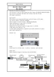
HD FULL DIGITAL TRIAX SYSTEM<br />
<strong>TU</strong>-<strong>HD1000</strong>/<strong>CX</strong>-<strong>HD1000</strong><br />
OPERATING INSTRUCTIONS<br />
Please read these operating instructions carefully for proper operation,<br />
and keep them for future reference.
SAFETY INSTRUCTIONS<br />
Carefully read all safety messages in this manual and safety Instructions on your equipment.<br />
Follow recommended precautions and safe operating practices.<br />
SAFETY ALERT SYMBOL<br />
!<br />
This is the “Safety Alert Symbol.” This symbol is used to call your attention to items or operations<br />
that could be dangerous to you or other persons using this equipment. Read these messages<br />
and follow these instructions carefully.<br />
It is essential that you read the instructions and safety regulations before you attempt to assemble or use<br />
this equipment.<br />
The definitions of signal words are as follows:<br />
!<br />
!<br />
WARNING<br />
CAUTION<br />
WARNING: Personal danger<br />
Warning notes indicate any condition or practice, which if not strictly observed, could result<br />
in personal injury or possible death.<br />
CAUTION: Possible damage to equipment<br />
Caution notes indicate any condition or practice, which if not strictly observed or remedied,<br />
could result in damage or destruction of the equipment.<br />
NOTE<br />
NOTE: Notes indicate an area or subject of special merit, emphasizing either the product′s<br />
capabilities or common errors in operation or maintenance.<br />
!<br />
WARNING:<br />
AVERTISSEMENT<br />
VORSICHT<br />
TO REDUCE THE RISK OF FIRE OR ELECTRIC SHOCK, DO NOT EXPOSE THIS<br />
COLOR CAMERA TO RAIN OR MOIS<strong>TU</strong>RE.<br />
Afin d’éviter tout risque d’incendie ou d’électrocution, ne pas exposer<br />
l’appareil á la pluie ou á l’humidité.<br />
Afin d’écarter tout risque d’électrocution, garder le coffret fermé. Ne confier<br />
l’entretien de l’appareil qu á un personnel qualifié.<br />
Um Feuergefahr und die Gefahr eines eiektrischen Schiages zu vermeiden,<br />
darf das Gerät weder Regen noch Feuchtigkeit ausgesetzt werden.<br />
Um einen elektrischen Schiag zu vermeiden, darf das Gehäuse richt geöffnet werden.<br />
Überiassen Sie Wartungsarbeiten stets nur einem Fachmann.<br />
A
IMPORTANT SAFETY INSTRUCTIONS<br />
1. Read Instructions<br />
All the safety and operating instructions should be read before the product is operated.<br />
2. Retain Instructions<br />
The safety and operating instructions should be retained for future reference.<br />
3. Heed Warnings<br />
All warnings on the product and the operating instructions should be adhered to.<br />
4. Follow Instructions<br />
All operating and use instructions should be followed.<br />
5. Cleaning<br />
Unplug this product from the wall outlet before cleaning. Do not use liquid cleaners or aerosol cleaners. Use a damp<br />
cloth for cleaning.<br />
6. Attachments<br />
Do not use attachments not recommended by the product manufacturer as they may cause hazards.<br />
7. Water and Moisture<br />
Do not use this product near water - for example, near a bath tub, wash bowl, kitchen sink, or laundry tub; in a wet<br />
basement; or near a swimming pool; and the like.<br />
8. Accessories<br />
Do not place this product on an unstable cart, stand, tripod, bracket, or table. The product may fall, causing serious<br />
injury to a child or adult, and serious damage to the product. Use only with a cart, stand, tripod, bracket, or table<br />
recommended by the manufacturer, or sold with the product. Any mounting of the product should follow the<br />
manufacturer's instructions, and should use a mounting accessory recommended by the manufacturer.<br />
9. Moving<br />
A product and cart combination should be moved with care.<br />
Quick stops, excessive force, and uneven surfaces may cause the product and cart combination to overturn.<br />
10. Ventilation<br />
Slots and openings in the cabinet are provided for ventilation and to ensure reliable operation of the product and to<br />
protect it from overheating, and these openings must not be blocked or covered.<br />
The openings should never be blocked by placing the product on a bed, sofa, rug, or other similar surface. This product<br />
should not be placed in a built-in installation such as a bookcase or rack unless proper ventilation is provided or the<br />
manufacturer's instructions have been adhered to.<br />
11. Power Sources<br />
This product should be operated only from the type of power source indicated on the marking label. If you are not sure<br />
of the type of power supply to your home, consult your product dealer or local power company. For products intended<br />
to operate from battery power, or other sources, refer to the operating instructions.<br />
12. Grounding or Polarization<br />
This product is equipped with a three-wire grounding-type plug a plug having a third (grounding) pin. This plug will<br />
only fit into a grounding-type power outlet. This is a safety feature. If you are unable to insert the plug into the outlet,<br />
contact your electrician to replace your obsolete outlet. Do not defeat the safety purpose of the grounding-type plug.<br />
13. Power-Cord Protection<br />
Power-supply cords should be routed to that they are not likely to be walked on or pinched by items placed upon or<br />
against them, paying particular attention to cords at plug, convenience receptacles, and the point where they exit from the<br />
product.<br />
B
14. Lightning<br />
For added protection for this product during a lightning storm, or when it is left unattended and unused for long periods<br />
of time, unplug it from the wall outlet. This will prevent damage to the product due to lightning and power-line surges.<br />
15. Overloading<br />
Do not overload wall outlets, extension cords or integral convenience receptacles as this can result in a risk of fire or<br />
electric shock.<br />
16. Object and Liquid Entry<br />
Never push objects of any kind into this product through openings as they may touch dangerous voltage points or<br />
short-out parts that could result in a fire or electric shock. Never spill liquid of any kind on the product.<br />
17. Inflammable and Explosive Substance<br />
Avoid using this product where there are gases, and also where there are inflammable and explosive substances in the<br />
immediate vicinity.<br />
18. Heavy Shock or Vibration<br />
When carrying this product around, do not subject the product to heavy shock or vibration.<br />
19. Servicing<br />
Do not attempt to service this product yourself as opening or removing covers may expose you to dangerous voltage or<br />
other hazards. Refer all servicing to qualified service personnel.<br />
20. Damage Requiring Service<br />
Unplug this product from the wall outlet and refer servicing to qualified service personnel under the following conditions:<br />
a. When the power-supply cord or plug is damaged.<br />
b. if liquid has been spilled, or objects have fallen into the product.<br />
c. If the product has been exposed to rain or water.<br />
d. If the product does not operate normally by following the operating instructions. Adjust only those controls that are<br />
covered by the operating instructions as an improper adjustment of other controls may result in damage and will often<br />
require extensive work by a qualified technician to restore the product to its normal operation.<br />
e. If the product has been dropped or damaged in any way.<br />
f. When the product exhibits a distinct change in performance-this indicates a need for service.<br />
21. Replacement Parts<br />
When replacement parts are required, be sure the service technician has used replacement parts specified by the<br />
manufacturer or have the same characteristics as the original part.<br />
Unauthorized substitutions may result in fire, electric shock, or other hazards.<br />
22. Safety Check<br />
Upon completion of any service or repairs to this product, ask the service technician to perform safety checks to<br />
determine that the product is in proper operating condition.<br />
23. Wall or Ceiling Mounting<br />
The product should be mounted to a wall or ceiling only as recommended by the manufacturer.<br />
24. Heat<br />
The product should be situated away from heat sources such as radiators, heat registers, stoves, or other products<br />
(including amplifiers) that produce heat.<br />
C
WICHTIGE SICHERHEITSANWEISUNGEN<br />
1. Alle Anweisungen lesen.<br />
Vor Betrieb des Erzeugnisses sollten alle Sicherheits-und Bedienungsanleitungen gelesen werden.<br />
2. Die Anweisungen aufbewahren.<br />
Die Sicherheits-und Bedienungsanleitungen sollten fünftigen Bezug aufbewahrt werden.<br />
3. Warnungen beachten.<br />
Die Warnungen auf dem Erzeugnis und in den Bedienungsanleitungen solten beachtet werden.<br />
4. Anweisungen befolgen.<br />
Alle Bedienungsanleitung-und<br />
Verwendungsanweisungen sollten befolgt werden.<br />
5. Reinigung<br />
Den Stecker des Geräts vor Reinigung aus der Steckdose ziehen. Keine flüssigen Reinigungsmittel oder Aerosolreiniger<br />
verwenden. Zum Reinigen einen feuchten Lappen verwenden.<br />
6. Zubehör<br />
Nur vom-Hersteller des Erzeugnisses empfohlenes Zubehör verwenden, da es sonst zu Störungen kommen kann.<br />
7. Wasser und Feuchtigkeit<br />
Dieses Erzeugnis nicht in der Nähe von Wasser verwenden - z.B, in der Nähe einer Badewanne, eines Waschbeckens,<br />
einer Küchenspüle, eines Waschzubers, in einem nassen Keller, in der Nähe eines Schwimmbeckens usw.<br />
8. Aufstellung<br />
Das Erzeugnis nicht auf einen unstabilen Wagen, Stand, Dreifuß, Träger oder Tisch stellen.<br />
Das Erzeugnis kann sonst herunterfallen und ein kind oder einen Erwachsenen schwer verietzen.<br />
Außerdem kann das Gerät schwer beschädigt werden. Nur mit einem Wagen, Stand, Dreifuß, Träger oder Tisch<br />
verwenden, der vom Hersteller empfohlen oder mit dem Erzeugnis verkauft worden ist. Für jegliche Anbringung sollten<br />
die Anweisungen des Herstellers befolgt werden, und das vom Hersteller empfohlene Anbringungszubehör sollte<br />
verwendet werden.<br />
9. Eine Kombination von Erzeugnis und Wagen sollte vorsichtig bewegt werden.<br />
Schneller Halt, übermäßige Krafteinwirkung und unebene Oberflächen können Umkippen der kombination von<br />
Erzeugnis und Wagen verursachen.<br />
10. Ventilation<br />
Schlitze und Öffnungen im Gehäuse dienen der Ventilation. Sie sind für zuverlässigen Betrieb des Gerätes und Schutz<br />
vor Überhitzung erforderlich und dürfen nicht blockiert oder abgedeckt werden.<br />
Die Öffnungen sollten niemals dadurch blockiert werden, daß, das Gerät auf ein Bett, ein Sofa, einen Teppich oder eine<br />
ähnliche Oberfläche gestellt wird.<br />
Das Gerät sollte nur dann in Einbauinstallierung wie in einem Bücherschrank oder einem Gestell verwendet werden,<br />
wenn angemessene Ventilation vorgesehen ist bzw. Die Anweisungen des Herstellers befolgt worden sind.<br />
11. Stromversorgung<br />
Dieses Erzeugnis sollte nur an der auf dem Typenschild angegebenen Stromversorgungsart betrieben werden. Wenn Sie<br />
nicht sicher sind, was für eine Stromversorgung Sie haben, so wenden Sie sich bitte an Ihren Erzeugnishändler oder an<br />
das lokale Elektrizitätswerk. Beziehen Sie sich für Batteriebetrieb oder andere Stromquellen vorgesehene Erzeugnisse<br />
bitte auf die Bedienungsanleitungen.<br />
D
12. Erdung oder Polarisierung<br />
Dieses Erzeugnis ist mit einem Schutzkontaktstecker mit drei Leitern ausgerüstet, mit einem Erdungskontakt. Dieser<br />
Stecker paßt nur in ein schuko-Steckdose. Dies ist eine Sicherheitsmaßnahme. Wenn Sie den Stecker nicht in die<br />
Steckdose stecken können, so wenden Sie sich bitte an ihren Elektriker, damit er die veraltete Schuts des<br />
Schutzkontaktsteckers unwirksam.<br />
13. Netzkabelschutz<br />
Netzkabel sollten so verlegt werden, deß möglichst nicht darauf getreten wird und daß sie nicht eingeklemmt werden, mit<br />
besonderer Beachtung der kabel an Stackern, Verlängerungskabeln und dem Austritt des Kabels aus dem Erzeugnis.<br />
14. Blitzschlag<br />
Für zusätzlichen Schutz des Erzeugnisses während eines Gewitters oder bei Nichtverwendung für lange Zeit den Stecker<br />
aus der Steckdose ziehen. Dies verhütet Beschädigung durch Blitzschlag und Netzspannungsstöße.<br />
15. Überlastung<br />
Wandsteckdosen, Verlängerungskabel und eingebaute Bequemlickkeitssteckdosen nicht überlasten, da dies Feuer oder<br />
elektrischen Schlag verursachen kann.<br />
16. Eindringen von Fremdkörpern und Flüssigkeit<br />
Niemals Objekte irgendwelcher Art durch die Öffnungen in das Gerät schieben, da diese unter hoher Spannung stehende<br />
Teile berühren oder kurzschließen können, wodurch es zu Feuer oder elektrischem Schlag kommen kann. Niemals<br />
Flüssigkeiten irgendwelcher Art auf das Erzeugnis verschütten.<br />
17. Entflammbare und explosive Substanzen<br />
Vermeiden Sie Verwendung dieses Erzeugnisses an Orten mit Gasen bzw. entflammbaren oder explosiven Substanzen<br />
in der direkten Umgebung.<br />
18. Starke stöße oder Vibrationen<br />
Setzen Sie das Erzeugnis beim Transport nicht starken Stößen oder Vibrationen aus.<br />
19. Wartung<br />
Versuchen Sie nicht, dieses Erzeugnis Selbst zu warten, da Sie sich durch Öffnen bzw. Entfernen von Abdeckungen<br />
hohen Spannungen und sonstigen Gefährdungen ausserzen können.<br />
Beziehen Sie sich für jegliche Wartung auf qualifiziertes Wartungspersonal.<br />
20. Beschädigung, die Wartung erfordert<br />
Ziehen Sie den Stecker dieses Erzeugnisses aus der Steckdose und wenden Sie sich an qualifiziertes Wartungspersonal,<br />
wenn eine der folgenden Bedingungen vorliegt:<br />
a. Wenn das Netzkabel oder der Stecker beschädigt ist.<br />
b. Bei Eindringen von Flüssigkeit oder Fremdkörpern in das Gerät.<br />
c. Wenn das Erzeugnis Regen oder Wasser ausgesetzt worden ist.<br />
d. Wenn das Erzeugnis bei Befolgen der Bedienungsanleitungen nicht normal funktioniert.<br />
Nur die Regelelemente verstellen, die in den Bedienungsanleitungen behandelt werden, da unangemessene Einstellung<br />
anderer Regelelemente Beschädigung verursachen kann und oft beträchtliche Arbeit durch einen qualifizierten<br />
Techniker erfordert, um das Erzeugnis wieder, zu normalem Betrieb zurückzubringen.<br />
e. Wenn das Erzeugnis fallen gelassen oder beschädigt worden ist.<br />
f. Wenn das Erzeugnis eine klare Änderung in der Leistung zeigt-dies weist darauf hin, daß Wartung erforderlich ist.<br />
E
21. Ersatzteile<br />
Wenn Ersatzteile erforderlich sind, darauf achten, daß der Wartungstechniker nur die vom Hersteller festgelegten<br />
Ersatzteile oder Teile mit den gleichen Charakteristiken wie die ursprünglichen Teile verwendet. Unautorisierte<br />
Ersatzteile können Feuer, elektrischen Schlag oder sonstige Gefährdungen verursachen.<br />
22. Sicherheitsprüfung<br />
Bitten Sie den Wartungstechniker nach der Vollendung von Wartung oder Reparaturarbeiten an diesem Erzeugnis um die<br />
Durchführung von Sicherheitsprüfungen, um zu bestimmen, daß das Erzeugnis im angemissenen Betriebszustand ist.<br />
23. Anbringung an der Wand oder an der Decke<br />
Das Erzeugnis sollte nur entsprechend den Empfehlungen des Herstellers an einer Wand oder an der Decke angebracht<br />
werden.<br />
24. Wärme<br />
Das Erzeugnis sollte fern von Wärmequellen wie Radiatoren, Heizwiderständen, Öfen und anderen Wärme erzeugenden<br />
Erzeugnissen (einschließlich Verstärkern) aufgestellt werden.<br />
F
MISES EN GARDE IMPORTANTES<br />
1. Lire les instructions<br />
Lire toutes les instructions de sécurité et de fonctionnement avant de faire fonctionner l’appareil.<br />
2. Conserver ces instructions<br />
Conserver les instructions de sécurité et de fonctionnement á des fins de référence ultérieure.<br />
3. Tenir compte des avertissements<br />
Tous les avertissements qui figurent sur l’appareil et dans le mode d’emploi devront être respectés.<br />
4. Observer les instructions<br />
Observer toutes les instructions de fonctionnement et d’utilisation.<br />
5. Nettoyage<br />
Avant de procéder au nettoyage, débrancher l’appareil de la prise secteur. Ne pas utiliser de produits de nettoyage<br />
liquides ou en aérosol.<br />
Nettoyer l’appareil avec un chiffon humide.<br />
6. Fixations<br />
Ne pas utiliser de fixations non recommandées par le fabricant de l’appareil car elles pourraient être source de danger.<br />
7. Eau et humidité<br />
Ne pas utiliser l’appareil á proximité d’eau-par exemple prés d’une baignoire, d’un lavabo, d’un évier ou d’un bac á<br />
lessive, dans un sous-sol humide, ou prés d’une piscine, etc.<br />
8. Accessoires<br />
Ne pas placer l’appareil sur un chariot, un socle, un pied, un support ou one table instables L’appareil pourrait tomber,<br />
blessant griévement des enfants ou des adultes, et étant sérieusement endommagé.<br />
Utiliser exclusivement le chariot, le socle, le pied, le support ou la table recommandés par le fabricant, ou vendus avec<br />
l’appareil. Pour tout montage de l’appareil, respecter les instructions du fabricant, et utiliser á cette fin l’accessoire de<br />
montage recommandé par le fabricant.<br />
9. L’appareil monté sur son chariot devra être déplacé avec précaution.<br />
Des arrêts brusques, une force excessive et des surfaces irréguliéres pourraient provoquer le renversement de<br />
l’ensemble appareil-chariot.<br />
10. Ventilation<br />
Les fentes et les ouvertures du coffret sont prévues pour la ventilation ainsi que pour garantir un fonctionnement en toute<br />
sécurité de l’appareil et le protéger de toute surchauffe, et ces ouvertures ne devront donc être ni obstruées ni recouvertes.<br />
Ne jamais obstruer les ouvertures en placant l’appareil sur un lit, un sofa, un tapis ou toute surface similaire. Ne jamais<br />
placer l’appareil dans un support confiné, par exemple une bibliothéque ou une é tagé re, sans ventilation suffisante ou<br />
sans repecter les instructions du fabricant.<br />
11. Sources d’allmentation<br />
L’appareil devra être alimenté exclusivement sur le type d’alimentation indiqué sur l’étiquette signalétique. Sil’on n’est<br />
pas sûr du type d’alimentatio du local, consulter le revendeur de l’appareil ou la compagnie d’électricité locale. Pour<br />
les appareils qui fonctionnent sur batterie ou sur d’autres sources, voir le mode d’emploi.<br />
12. Mise á la terre ou polarisation<br />
L’appareil est doté d’une fiche trifilaire avec mise á la terre, dont la troisiéme broche assure la mise á la terre. Cette<br />
fiche ne rentrera que dans les prises trifilaires de mise á la terre. Ceci est une mesure de sécurité. Si la fiche ne rentre<br />
pas dans la prise, faire remplacer la prise désuéte par un électricien.<br />
Ne pas rendre vaine la measure de sécurité assurée par cette prise avec mise á la terre.<br />
13. Protection du cordon d’alimentation<br />
Acheminer les cordons d’alimentation de facon qu’on ne risque pas de marcher dessus ou de les coincer sous un objet<br />
placé dessus ou contre eux.<br />
Faire particuliérement attention aux fiches des cordons, á la proximité des prises, et á l’endroit oú ils ressortent de<br />
l’appareil.<br />
G
14. Foudre<br />
Pour renforcer la protection de l’appareil pendant un orage, ou si l’on s’en éloigne ou qu’on reste longtemps sans<br />
l’utiliser, le débrancher de la source d’alimentation. Ceci permettra d’éviter tout dommage de l’appareil dú á la foudre<br />
et aux surtensions de ligne.<br />
15. Surcharge<br />
Ne pas surcharger les prises, rallonges et prises multiples car cela pourrait entraîner un risque de feu ou de choc<br />
électrique.<br />
16. Pénétration d’objets et de liquides<br />
Ne jamais enfoncer d’objets d’aucune sorte dans les ouvertures de l’appareil car ils pourraient toucher des points de<br />
tension dangereuse ou court-circuiter des piéces, ce qui pourrait provoquer un feu ou un choc électrique. Ne jamais<br />
renverser de liquide d’aucune sorte sur l’appareil.<br />
17. Substances inflammabes et explosives<br />
Eviter d’utiliser l’appareil en présence de gaz, ainsi qu’á proximité immédiate de substances inflammables et explosives.<br />
18. Chocs ou vibrations violents<br />
Lorsqu’on transporte l’appareil, ne pas le soumettre á des chocs ou des vibrations violents.<br />
19. Réparations<br />
Ne pas tenter de réparer l’aapareil soi-même car le fait d’ouvrir ou de retirer les caches risque d’exposer l’utilisateur á<br />
des tensions dangereuses notamment. Confier toute réparation á un personnel qualifié.<br />
20. Dommages nécessitant réparations<br />
Débrancher l’appareil de la source d’alimentation et confier les réparations á un personnel qualifié dans les cas suivants:<br />
a. Lorsque le cordon d’alimentation ou sa fiche sont endommagés<br />
b. Si du liquide s’est renversé sur l’appareil ou que des objets sont tombés dedans<br />
c. Si l’appareil a été exposé á la pluie ou á l’eau.<br />
d. Si l’appareil ne fonctionne pas normalement lorsqu’on observe les instructions d’utilisation.<br />
Ne régler que les commandes couvertes par le mode d’emploi ; en effet, un réglage incorrect des autres commandes<br />
pourrait entrainer des dommages et nécessiteront souvent des travaux de réparation coûteux par un technicien qualifié<br />
pour remettre l’appareil en état de marche.<br />
e. Si l’appareil est tombé ou qu’il a été endommagé.<br />
f. Si l’appareil affiche une nette modification de ses performances, cela signifie qu’il a besoin d’être réparé.<br />
21. Piéces de rechange<br />
Si l’on a besoin de piéces de rechange, veiller á ce que le technicien de réparation utilise exclusivement les piéces de<br />
rechange spécifiées par le fabricant ou des piéces ayant les mêmes caractéristiques que les piéces d’origine. Les piéces<br />
de rechange non autorisées risquent de provoquer un feu, un choc électrique et autres dangers.<br />
22. Vérificaton de sécurité<br />
Aprés tout travail d’entretien ou de réparation de l’appareil, demander au technicien de réparation d’effectuer les<br />
vérifications de sécurité pour s’assurer que l’appareil est en bon état de marche.<br />
23.Montage au mur ou au plafond<br />
L’appareil ne pourra être monté au mur ou au plafond que de la maniére recommandée par le fabricant.<br />
24. Chaleur<br />
Eloigner l’appareil des sources de chaleur, telles que radiateurs, appareils de chauffage, cuisiniéres, et de tour produit<br />
engendrant de la chaleur (y compris les amplificateurs).<br />
H
IMPORTANT NOTICE<br />
For USA<br />
These products have been tested and found to comply with the limits for a Class A digital device,<br />
pursuant to Part 15 of the FCC Rules. These limits are designed to provide reasonable protection<br />
against harmful interference when the equipment is operated in a commercial environment. This<br />
equipment generates, uses, and can radiate radio frequency energy and, if not installed and used in<br />
accordance with the instruction manual, may cause harmful interference to radio communications.<br />
Operation of this product in a residential area is likely to cause harmful interference in which case<br />
the user will be required to correct the interference at his own expense.<br />
WARNING<br />
Changes or modifications not expressly approved by <strong>Hitachi</strong> <strong>Kokusai</strong> <strong>Electric</strong> responsible for<br />
compliance could void the users authority to operate the equipment.<br />
For Canada<br />
This product does not exceed the class A/class B limits for radio noise emissions from digital<br />
apparatus as set out in the radio interference regulations.<br />
Le pr⎡sent appareil n⎡met pas de bruits radio⎡lectriques d⎡passant les limit⎡s applicable aux<br />
appareils num⎡riques de classe A prescrites dans le rVglement sur le brouillage radio⎡lectrique<br />
⎡dicter par le minist⎡re des communications du canada.<br />
I
Contents<br />
Outline and features····································································································· 1<br />
Warnings and cautions when using·············································································· 2<br />
Facility names and functions ························································································ 3<br />
System operation ········································································································· 9<br />
Triax cable connection ······························································································· 12<br />
Function menu ··········································································································· 13<br />
Backup battery replacement······················································································· 22<br />
System Configuration································································································· 23<br />
Service information<br />
Connector pin diagrams························································································· 24<br />
Intercom system setting ························································································· 29<br />
External View ············································································································· 30<br />
Specification··············································································································· 32
Outline and features<br />
1.Outline<br />
<strong>Hitachi</strong>'s Digital Triax cable transmission system addresses two application requirements posed by our<br />
customers worldwide. It is the next best, completely digital signal transport compared to that using<br />
fiber-optic cable. No other HDTV triax cable transmission system comes close.<br />
Second, in applications where traditional triax system is already in use, substantial savings in the cabling<br />
infrastructure can be realized by employing <strong>Hitachi</strong> HDTV Digital Triax cameras.<br />
<strong>Hitachi</strong>'s patented Digital Triax System consists of the camera head Triax adaptor and the<br />
corresponding <strong>TU</strong>-<strong>HD1000</strong> camera control unit.<br />
2.Features<br />
(1) High-quality transmission using <strong>Hitachi</strong>’s patented digital triax technology<br />
A high-quality video signal, audio signal, and control signal are digitally multiplexed into a triax cable.<br />
(2) High-performance down converter<br />
● A FPGA for processing SD video signals besides HD is built in, which enables DTL correction to be<br />
adjusted independently.<br />
● SD aspect ratio is switchable between 16:9 and 4:3.<br />
● For SD VBS output, a digital comb filter is available to reduce cross color noise.<br />
(3) Built-in up converter<br />
An up converter expands the SDTV signal of return video to the HDTV signal for the View-Finder. In<br />
addition, color signals can be input and View-Finder color displayed.<br />
(4) Built-in cross converter<br />
<strong>TU</strong>-<strong>HD1000</strong> supports both 1080i (SMPTE274M) and 720p (SMPTE296M) video on HD-SDI input /<br />
output.<br />
(5) SDI Embedded audio<br />
Two channels of MIC audio can be embedded in HD-SDI/SD-SDI output. (SMPTE 299M/272M)<br />
(6) Similar Input/Output as CU-<strong>HD1000</strong><br />
1
Warnings and cautions when using<br />
CAUTION<br />
Do not disassemble or modify<br />
The camera contains precision internal<br />
components. Do not open the cover or disturb<br />
switches and controls other than designated.<br />
There is risk of impaired performance and<br />
damage.<br />
Keep foreign object out of interior<br />
Entry of water, metallic or other foreign<br />
materials can cause failure and damage.<br />
Select use and storage locations carefully<br />
Avoid using or storing the equipment in the<br />
following types of locations. Impaired<br />
performance and damage can be caused.<br />
Extremely hot or cold locations (exceeding 0<br />
to 40°C), such as in enclosed vehicles.<br />
Subject to strong vibration.<br />
Humid or dusty locations.<br />
Salt spray or corrosive gases.<br />
Strong electromagnetic fields (e.g., near TV or<br />
radio transmitters).<br />
Where exposed to rain.<br />
When connecting and disconnecting cables,<br />
grasp the connector by the body, not the<br />
attached cable. Cables can be damaged by<br />
pulling on them.<br />
Fuse replacement<br />
Important: Although spare fuses are provided,<br />
the fuse must be replaced only by a qualified<br />
service technician.<br />
In event of difficulty<br />
Disconnect from power and contact the nearest<br />
<strong>Hitachi</strong> <strong>Kokusai</strong> <strong>Electric</strong> service agency.<br />
2
Facility names and functions<br />
<strong>TU</strong>-<strong>HD1000</strong><br />
8 6 7<br />
4<br />
2<br />
3<br />
5<br />
1<br />
11 9 12<br />
10<br />
1 CCU POWER switch<br />
CCU power on/off switch.<br />
2 CCU POWER LED<br />
Lights when power is on.<br />
3 CABLE CHECK LED<br />
OK: CAMERA POWER switch 4 can be<br />
operated.<br />
OPEN: Fiber cable not connected.<br />
SHORT: Excess current in fiber cable.<br />
Note: CAMERA POWER switch 4 is<br />
inoperative when OPEN, SHORT LED is<br />
lighted.<br />
4 CAMERA POWER switch<br />
Camera power on/off switch; lights at power on.<br />
When the camera power is off, only one channel<br />
intercom (CH1) is available.<br />
Press the switch for 3 sec. or more, the camera power<br />
turns off.<br />
5 GL ON LED<br />
Lights during genlock operation.<br />
Note: When a different frame rate signal is input for<br />
genlock, the LED blinks and the signal is<br />
ignored.<br />
6 R TALLY LED<br />
Lights at red tally input or when sending CALL signal<br />
from camera.<br />
7 G TALLY LED<br />
Lights at green tally input.<br />
8 CALL button<br />
Press to call the camera.<br />
9 INTERCOM LEVEL control<br />
Adjusts intercom listening volume.<br />
10 TALK ON/OFF switch<br />
Intercom microphone on/off switch.<br />
11 PRIVATE/COMM switch<br />
PRIVATE: Communicate with camera only<br />
COMM: Communicate with entire system<br />
12 Intercom connector (XLR,5P)<br />
Connection for optional MT-12MF headset.<br />
3
Facility names and functions<br />
13<br />
14<br />
22<br />
17<br />
15<br />
18<br />
19<br />
23<br />
27<br />
16<br />
21<br />
20<br />
26<br />
37<br />
35<br />
33<br />
36<br />
38<br />
34<br />
28 30 29 32 31<br />
25<br />
24<br />
13 HD SDI OUT connectors (BNC)<br />
Outputs three lines of digital serial HDTV video<br />
signals.<br />
14 HD/SD SDI connectors (BNC)<br />
Outputs four lines of digital serial HDTV/SDTV<br />
video signals.<br />
Select the HD-SDI or SD-SDI by the user function<br />
menu.<br />
The character is superimposed in PIX output.<br />
15 D.RET input connectors (BNC)<br />
Inputs for digital serial AUX video signals.<br />
A signal selected among these four inputs is sent to<br />
the camera viewfinder or the SK-<strong>HD1000</strong>’s RET<br />
connector<br />
The signal can be selected by user function menu..<br />
16 ENCR OUT connectors (BNC)<br />
Composite video outputs for 3 lines.<br />
17 COMPONENT/RGB connectors (BNC)<br />
R, G, B or Y, Pb, Pr signal outputs.<br />
The output signals are selected by menu.<br />
18 PIX OUT connector (BNC)<br />
Composite or R/G/B video output with superimposed<br />
character.<br />
19 WFM OUT connector (BNC)<br />
Composite or R/G/B video output for waveform<br />
monitor.<br />
20 Analog RET-1 input connectors (BNC)<br />
Inputs for analog AUX video signals. The signal is<br />
sent to the camera viewfinder or the SK-<strong>HD1000</strong><br />
RET connector (selected by pressing RET1 of the<br />
<strong>CX</strong>-<strong>HD1000</strong>).<br />
21 Analog RET-2 input connectors (BNC)<br />
Same function as analog RET-1.<br />
22 PROMPT connectors (BNC)<br />
Input for the prompter video signal. The signal is sent<br />
to the <strong>CX</strong>-<strong>HD1000</strong> PROMPT out connector.<br />
Important notice<br />
When using return video, please input correct format signal which is selected on the<br />
return assignment menu (page 18).<br />
4
Facility names and functions<br />
23 Genlock connectors (BNC)<br />
Input for tri-level sync signal or black burst signal for<br />
genlock operation.<br />
24 AC IN connector<br />
Input for AC power supply.<br />
25 FG terminal<br />
Frame ground terminal.<br />
26 Triax connector<br />
Connect Triax cable.<br />
27 COAX connector<br />
When the <strong>TU</strong>-<strong>HD1000</strong> is used for TRIAX mode,<br />
connect the attached accessory cable to the COAX<br />
connector as shown below.<br />
When this connector is used for COAX mode,<br />
disconnect the accessory jumper cable and connect a<br />
coaxial cable to the right side connector as viewed<br />
form the back side. Since these connectors cannot be<br />
used in conjunction with the TRIAX connector 26 ,<br />
do not connect a cable to both the TRIAX connector<br />
26 and left COAX connector as viewed from the<br />
back side at the same time.<br />
28 REMOTE1 connector<br />
Connection for the optional camera control panel or<br />
setup control unit.<br />
29 RS-232C connector<br />
Use for camera control via RS-232C.<br />
30 REMOTE2 connector<br />
Connection for the optional camera control panel or<br />
setup control unit.<br />
31 TALLY OUT connector<br />
Contact outputs for tally signals.<br />
32 COMMUNICATION connector<br />
Intercom and tally inputs from external system.<br />
33 MIC REMOTE connector<br />
This connector is used to select the MIC1 and MIC2<br />
amplifier gains.<br />
34 WFM CONTROL connector<br />
This connector is used to select the display mode of<br />
the waveform monitor.<br />
35 MIC OUT1 connector (XLR 3 pin)<br />
Outputs MIC1 audio signals from a camera or the<br />
<strong>CX</strong>-<strong>HD1000</strong> at 0 dBm.<br />
36 MIC OUT2 connector (XLR 3 pin)<br />
Outputs MIC2 audio signals from the <strong>CX</strong>-<strong>HD1000</strong> at<br />
0 dBm.<br />
37 RJ-45 connector<br />
This connector is used to connect expanded functions<br />
such as a remote controller.<br />
38 TALLY CONTACT/VOLTAGE<br />
The TALLY input can be contact or voltage supply.<br />
Set the TALLY switches according to the systems<br />
connected to <strong>TU</strong>-<strong>HD1000</strong> rear panel<br />
COMMUNICATION connector.<br />
5
Facility names and functions<br />
<strong>CX</strong>-<strong>HD1000</strong><br />
3<br />
4<br />
2<br />
6<br />
1<br />
5<br />
7<br />
8<br />
1 POWER switch<br />
EXT : Power supplied via DC input connector.<br />
CCU : Power supplied via triax cable.<br />
When power is supplied via the triax cable<br />
and the switch is set to EXT, the protector<br />
operates to cut off the camera head power.<br />
2 CALL button<br />
Press to call the CCU.<br />
3 Viewfinder attachment<br />
The 5-inch or other viewfinder can be<br />
attached by using viewfinder adapter the AT-<br />
500/AT-550<br />
4 Shoulder belt hook<br />
Attachment for optional shoulder belt.<br />
5 TRIAX CONNECTOR<br />
Triax cable connection.<br />
6 AC230V output connector<br />
Outputs the 230 VAC.<br />
7 HD-SDI2 output connector (BNC)<br />
HD-SDI/SD-SDI signal output (75Ω).<br />
Following 5 types of output signal can be<br />
selected by camera menu.<br />
!<br />
Video type<br />
Format<br />
1 Camera HD-SDI<br />
2 Camera (Down-converted) SD-SDI<br />
3 Return HD-SDI<br />
4 Return (Down-converted) SD-SDI<br />
5 Prompter SD-SDI<br />
8 PROMPT output/GL input connector (BNC)<br />
In CCU system operation, following 3 types of<br />
output signal can be selected by camera<br />
menu.<br />
Video type<br />
Format<br />
1 Prompter VBS<br />
2 Return (Down-converted) VBS<br />
3 Camera (Down-converted) VBS<br />
In stand-alone operation, this connector is<br />
input for genlock signal.<br />
CAUTION: 6 AC230V output connector<br />
Use FS-F5 Full Servo Adaptor.<br />
When you attach/remove the adaptor,<br />
turn off the camera power.<br />
6
Facility names and functions<br />
9<br />
10<br />
11<br />
12<br />
13<br />
14<br />
15<br />
16<br />
17<br />
20<br />
19<br />
18<br />
9 CS switch<br />
On/off of function set at the CUSTOM SW<br />
menu.<br />
10 TALLY ON/OFF switch<br />
Turn off this switch to prevent R/G TALLY LED..<br />
11 R/G TALLY LED<br />
Lights at green or red tally input.<br />
12 RET1 transmission signal switch<br />
This switch is used to select a signal input to the<br />
RET-1 of the CCU. This switch is a four-position<br />
slide switch, and the type of signals sent through<br />
this switch can be set by menu.<br />
13 RET1 switch<br />
Controls the receiving sound volume of the<br />
program.<br />
14 INCOM1 PGM 1 / PGM 2 level<br />
Controls the receiving sound volume of the<br />
program.<br />
15 INCOM 1 intercom level<br />
Controls the receiving sound volume of the<br />
intercom.<br />
16 INCOM 1 TALK ON/OFF switch<br />
Turns on/off the microphone of intercom 1<br />
17 INCOM 1 PD/ENG select switch<br />
This switch is used to select the PD or ENG<br />
input of the external intercom system to be<br />
connected to the CCU rear side...<br />
18 INTERCOM 1 / INTERCOM 2 connector<br />
(XLR 5 pin)<br />
The headset can be connected.<br />
- Note -<br />
Use the head set with XLR 5 pin.<br />
19 SCRIPT connector<br />
Supply the 12V/0.3A max for script lamp.<br />
20 RET CONT connector<br />
This signal is used to remotely control TALK<br />
ON/OFF, RET1 ON/OFF, and RET2 ON/OFF for<br />
the INTERCOM 1.<br />
sent to the camera viewfinder or the SK-<strong>HD1000</strong><br />
RET connector (selected by pressing RET1 of the<br />
<strong>CX</strong>-<strong>HD1000</strong>).<br />
7
Facility names and functions<br />
21 22 23 24 25<br />
26<br />
21 DC IN connector (XLR 4 pin)<br />
This connector should be used when the camera<br />
is used in stand-alone mode.<br />
22 MIC SEL switch<br />
The front microphone connector or rear<br />
microphone connector mike can be selected.<br />
23 MIC1 /MIC2 connector (XLR 3 pin)<br />
Connector for microphone.<br />
24 MIC LINE/OFF/+48V switch<br />
LINE: For a line level signal source<br />
OFF: Not to supply a power<br />
+48v: To supply a power of +48VDC<br />
25 HD-SDI 1 output connector (BNC)<br />
HD-SDI output for camera video.<br />
26 Extension connector (D-sub 29pin)<br />
Interface connector for studio adaptor.<br />
8
System Operation<br />
■ CAMERA SYYSTTEM OPERATTION<br />
Attach the <strong>CX</strong>-<strong>HD1000</strong> triax adaptor to the camera. Then connect the camera control panel and setup control unit to the<br />
<strong>TU</strong>-<strong>HD1000</strong>. The camera control panel and the setup control unit can be connected to the <strong>TU</strong>-<strong>HD1000</strong> and operate<br />
simultaneously.<br />
1. TRIAX mode (AC) operation<br />
When the <strong>TU</strong>-<strong>HD1000</strong> CCU POWER switch is set to ON, the triax cable connection is checked automatically (about 10<br />
seconds), then power can be supplied to the camera by pressing the CAMERA POWER button to produce a video output<br />
signal.<br />
The CABLE CHECK LED lights OK when the triax cable is normal.<br />
The intercom can be used when the CCU POWER switch is ON.<br />
Note: Camera power is not supplied in the following situations.<br />
・Not connected the triax cable between the <strong>TU</strong>-<strong>HD1000</strong> and the <strong>CX</strong>-<strong>HD1000</strong>.<br />
・Not connected the attached as accessory COAX cable in rear panel of the <strong>TU</strong>-<strong>HD1000</strong> rear panel.<br />
・The Defective triax cable has been using.<br />
・The Power switch in the <strong>CX</strong>-<strong>HD1000</strong> set to EXT mode or the CAMERA POWER turn OFF.<br />
Connect the accessory COAX cable as shown<br />
right picture.<br />
9
System Operation<br />
2. COAX mode (DC) operation<br />
The <strong>CX</strong>-<strong>HD1000</strong> can operate with 12VDC power supply and coax cable connection (conversion connector required).<br />
Set the <strong>CX</strong>-<strong>HD1000</strong> POWER switch to EXT. Turn on the CCU POWER switch of the <strong>TU</strong>-<strong>HD1000</strong> and select the<br />
COAX mode with menu. The COAX mode is selected and video signals are output.<br />
Connect the coax cable to the right side female BNC<br />
connector as shown right picture.<br />
*In case use the coax cable, maximum cable length<br />
may change with using the coax cable performance.<br />
3. Camera stand alone operation<br />
Supply 12VDC to the <strong>CX</strong>-<strong>HD1000</strong>, but do not connect either triax or coax cable. The camera can be operated in<br />
stand-alone mode.<br />
The video signals are output from the VIDEO OUT and MONI OUT connectors and the SDI OUT connector on the<br />
<strong>CX</strong>-<strong>HD1000</strong> rear side.<br />
10
Triax adaptor attachment<br />
Triax adaptor installation<br />
Install the triax adaptor <strong>CX</strong>-<strong>HD1000</strong> .<br />
Installation<br />
1. Align the adapter guide pin with the camera guide shoe. Press to insert the adapter.<br />
2. Tighten screws 1, 2 and 3 to secure the camera adapter.<br />
1<br />
2<br />
3<br />
CAUTION<br />
Tighten screws fully to prevent wobble between adapter and camera.<br />
11
Triax cable connection<br />
The triax cable connector has a locking mechanism. Release the lock to disengage the<br />
connector.<br />
1. Kings connector<br />
<strong>TU</strong>-<strong>HD1000</strong><br />
<strong>CX</strong>-<strong>HD1000</strong><br />
Slide the plug connector ring outward when<br />
disengaging the connector.<br />
2. Fischer connector<br />
<strong>TU</strong>-<strong>HD1000</strong><br />
Press the socket connector ring downward when<br />
disengaging the connector.<br />
<strong>CX</strong>-<strong>HD1000</strong><br />
Press the socket connector ring downward when<br />
disengaging the connector.<br />
3. Tajimi connector<br />
<strong>TU</strong>-<strong>HD1000</strong><br />
Slide the plug connector ring outward when<br />
disengaging the connector.<br />
<strong>CX</strong>-<strong>HD1000</strong><br />
Press the socket connector ring downward when<br />
disengaging the connector.<br />
Slide the plug connector ring outward when<br />
disengaging the connector.<br />
12
Function menu<br />
Function menu<br />
Use the camera control panel or the setup control unit connected to the <strong>TU</strong>-<strong>HD1000</strong> rear side to display the function menus.<br />
The function menus include the CCU menu to set the <strong>TU</strong><strong>HD1000</strong> and the camera menu to set a camera.<br />
(And also the function menus control the button of the <strong>TU</strong>-SD.Digital unit inside the <strong>TU</strong>-<strong>HD1000</strong>.)<br />
MENU<br />
RU-3400<br />
3400VR<br />
VR/JYY<br />
JYY-S10<br />
RU-1200<br />
1200VR<br />
VR/JYY<br />
MENU<br />
CTL<br />
HEAD<br />
RU-1000<br />
1000VR<br />
BARS<br />
SHUTTER<br />
MASTER CAIN<br />
UP<br />
ND<br />
HEAD<br />
CC<br />
UP<br />
DOWN<br />
LEFT<br />
RIGHT<br />
When MEMU button is active, ND button and<br />
CC button are assigned for UP/DOWN and<br />
LEFT/RIGHT respectivellyy.<br />
MENU<br />
LEFT<br />
DOWN<br />
RIGHT<br />
<strong>TU</strong>-<strong>HD1000</strong><br />
Right-front of <strong>TU</strong>-D.SD-DIGITAL unit<br />
CAM PWR<br />
OFF ⇔ ON<br />
UP DOWN LEFT RIGHT SET<br />
ADJUST<br />
UP<br />
DOWN<br />
LEFT<br />
RIGHT<br />
MENU<br />
13
Function menu<br />
CCU menu<br />
If the FUNC button of the camera control panel is pressed with the color bar ON, the CCU menu is displayed.<br />
■<strong>TU</strong>-FUNCTION<br />
■RE<strong>TU</strong>RN SELECT<br />
■MIC GAIN<br />
■SYSTEM TIMING<br />
BUZZER :ENABLE<br />
SDI SELECT :HD SDI<br />
SDI PIX :HD SDI<br />
SDI AUDIO :OFF<br />
CCU ID : 1<br />
CABLE TYPE :TRIAX MODE<br />
TV FORMAT: 1080i<br />
50.00Hz<br />
TIME/DATE: '08.01.01<br />
12:00<br />
RET.CH SELECT<br />
CH1 :D.RET1<br />
CH2 :D.RET2<br />
CH3 :A.RET1<br />
CH4 :A.RET2<br />
ASSIGNMENT :<br />
MIC1<br />
MIC2<br />
:-60dB<br />
:-60dB<br />
HD H PHASE : 0( 0)<br />
SD SDI H P : 0( 0)<br />
SD VBS H P : 108( 1728)<br />
SC CORASE : 0°<br />
SC FINE : 0( 0)<br />
SD Y LEVEL : 0<br />
C LEVEL : 0<br />
■TV FORMAT<br />
□1080i<br />
□720p<br />
SET DATA :PUSH +<br />
■TIME/DATE<br />
DATE DISP :Y.M.D<br />
TIME DISP :ON<br />
YEAR :08<br />
MONTH :01<br />
DAY :01<br />
HOUR :12<br />
MINUTE :00<br />
SET DATA :PUSH +<br />
■ASSIGNMENT<br />
SELECT TYPE<br />
D.RET1 :HD SDI<br />
D.RET2 :HD SDI<br />
D.RET3 :SD SDI 16:9<br />
D.RET4 :SD SDI 4:3<br />
A.RET1 :SD VBS 16:9<br />
A.RET2 :SD VBS 4:3<br />
■SD SETTING<br />
■SD DTL<br />
■PIX DISPLY<br />
OUTPUT :RGB<br />
COMB FILTER :OFF<br />
ASPECT :16:9<br />
WFM :ENC<br />
COMP SE<strong>TU</strong>P :ON<br />
R-Y/B-Y LEV :100%<br />
SD DTL :ON<br />
H GAIN : 0<br />
V GAIN : 0<br />
H CRISP :-128<br />
V CRISP :-128<br />
DTL FREQ :5MHz<br />
LEVEL DEP :-128<br />
LEV DEP SLP:-128<br />
FILTER<br />
ECC<br />
IRIS<br />
:ON<br />
:ON<br />
:ON<br />
Camera menu<br />
The camera menu appears when the color bar is off. Contents differ by the camera. Refer to the camera operating instructions.<br />
14
Function menu<br />
<strong>TU</strong>-FUNCTION menu<br />
■<strong>TU</strong>-FUNCTION<br />
BUZZER :ENABLE<br />
SDI SELECT :HD SDI<br />
SDI PIX :HD SDI<br />
SDI AUDIO :OFF<br />
CCU ID : 1<br />
CABLE TYPE :TRIAX MODE<br />
TV FORMAT: 1080i<br />
50.00Hz<br />
TIME/DAT: ’09.01.01<br />
12:00<br />
Item Setting Factory setting Description<br />
BUZZER ENABLE, DISABLE ENABLE Sets buzzer operation during call input.<br />
ENABLE : Buzzer sounds.<br />
DISABLE : Buzzer does not sound.<br />
SDI SELECT HD SDI, SD SDI HD SDI Sets output signal of HD/SD-SDI OUT connector.<br />
SDI PIX HD SDI, SD SDI HD SDI Sets output signal of HD/SD-SDI OUT(PIX) connector.<br />
SDI AUDIO ON,OFF OFF Sets the embedded audio ON/OFF of the HD-SDI /SD-SDI<br />
output.<br />
CCU ID 1 ~ 12 1 Set the CCU ID.<br />
This ID is required for the SE<strong>TU</strong>P CONTROL UNIT to<br />
identify the CCU when the SE<strong>TU</strong>P CONTROL UNIT is<br />
used.<br />
CABLE TYPE<br />
TRIAX MODE,<br />
TRIAX MODE<br />
Set the Cable type.<br />
COAX MODE<br />
TV FORMAT<br />
Used to display the TV FORMAT submenu<br />
TV FORMAT menu<br />
TIME/DATE<br />
Used to display the TIME/DATA submenu.<br />
■TV FORMAT<br />
☑1080i<br />
□720p<br />
SET DATA :PUSH +<br />
Item Setting Factory setting Description<br />
1080i ☑, □ ☑ Select the TV FORMAT 1080i(HD-SDI IN/OUT)<br />
☑:SELECTED<br />
□:NOT SELECTED<br />
720p ☑, □ □ Select the TV FORMAT 720p(HD-SDI /INOUT)<br />
SET DATA PUSH + - Press the and buttons together to enable the TV<br />
FORMAT setting.<br />
NOTICE:<br />
The cursor is moved to an arbitrary format with an upper and lower switch, and when TV FORMAT is set, a right and left<br />
switch is operated, and set. The ☑ mark is displayed by pushing a right and left switch, and TV FORMAT is changed.<br />
After TV FORMAT is set, it saves the setting data by matching the cursor to “SET DATA", and pushing a right and left<br />
switch at the same time. It returns to TV FORMAT before it changes automatically when it does not save the setting data<br />
within ten seconds.<br />
TV FORMAT returns to TV FORMAT before it changes automatically when the following operation is done.<br />
(1) When it does not save the setting data within ten seconds.<br />
(2) When it turns off the menu display before it saves the setting data.<br />
(3) When it changes to “CU-FUNCTION MENU" before it saves the setting data.<br />
(4) When it turns off the CCU power supply before is saves the setting data.<br />
15
Function menu<br />
TIME/DATE menu<br />
■TIME/DATE<br />
DATE DISP :Y.M.D<br />
TIME DISP :ON<br />
YEAR :08<br />
MONTH :01<br />
DAY :01<br />
HOUR :12<br />
MINUTE :00<br />
SET DATA :PUSH +<br />
Item Setting Factory setting Description<br />
DATE DISP OFF, Y.M.D,<br />
M.D.Y, D.M.Y<br />
Y.M.D<br />
Sets the date display.<br />
When ON is selected, the CU-FUNCTION menu displays<br />
the date.<br />
TIME DISP OFF, ON ON Sets the time display.<br />
When ON is selected, the CU-FUNCTION menu displays<br />
the time.<br />
YEAR 00 ~ 99 - Sets the year of the date.<br />
MONTH 00 ~ 12 - Sets the month of the date.<br />
DAY 00 ~ 31 - Sets the day of the date.<br />
HOUR 00 ~ 23 - Sets the hours of the time.<br />
MINUTE 00 ~ 59 - Sets the minutes of the time.<br />
SET DATA PUSH + - Press the and buttons together to enable the<br />
TIME/DATE setting.<br />
16
Function menu<br />
RE<strong>TU</strong>RN SELECT menu<br />
■RE<strong>TU</strong>RN SELECT<br />
RET.CH<br />
SELECT<br />
CH1<br />
:D.RET1<br />
CH2<br />
:D.RET2<br />
CH3<br />
:A.RET1<br />
CH4<br />
:A.RET2<br />
ASSIGNMENT :<br />
Item Setting Factory setting Description<br />
CH1 D,RET1,<br />
D,RET2,<br />
D.RET1 Selects the RET signal when the RET1 transmission signal<br />
switch of the <strong>CX</strong>-<strong>HD1000</strong> is set to 1.<br />
D,RET3,<br />
CH2 D,RET4,<br />
A,RET1,<br />
D.RET1 Selects the RET signal when the RET2 transmission signal<br />
switch of the <strong>CX</strong>-<strong>HD1000</strong> is set to 2.<br />
A,RET2<br />
CH3 D.RET1 Selects the RET signal when the RET3 transmission signal<br />
switch of the <strong>CX</strong>-<strong>HD1000</strong> is set to 3.<br />
CH4<br />
D.RET1<br />
Selects the RET signal when the RET4 transmission signal<br />
switch of the <strong>CX</strong>-<strong>HD1000</strong> is set to 4.<br />
ASSIGNMENT - Used to display the ASSIGNMENT submenu.<br />
ASSIGNMENT menu<br />
■ASSIGNMENT<br />
SELECT<br />
TYPE<br />
D.RET1 :HD SDI<br />
D.RET2 :SD SDI16:9<br />
D.RET3 :SD SDI 4:3<br />
D.RET4 :SD SDI<br />
A.RET1 :SD VBS16:9<br />
A.RET2 :SD VBS 4:3<br />
Item Setting Factory setting Description<br />
D.RET1 HD SDI,<br />
HD SDI The transmission signal set to digital return 1 is selected.<br />
SD SDI16:9,<br />
D.RET2 SD SDI 4:3, HD SDI The transmission signal set to digital return 2 is selected.<br />
D.RET3 SD SDI 16:9 The transmission signal set to digital return 3 is selected.<br />
D.RET4<br />
SD SDI 4:3<br />
The transmission signal set to digital return 4 is selected.<br />
A.RET1 SD VBS16:9, SD VBS16:9 The transmission signal set to analog return 1 is selected.<br />
SD VBS 4:3<br />
A.RET2<br />
SD VBS 4:3<br />
The transmission signal set to analog return 2 is selected.<br />
MIC GAIN menu<br />
■MIC GAIN<br />
MIC1<br />
MIC2<br />
:-60dB<br />
:-60dB<br />
Item Setting Factory setting Description<br />
MIC1 GAIN -10dB, -20dB, -30dB, -60dB<br />
Sets the sensitivity of the MIC1 line.<br />
-40dB, -50dB, -60dB, -70dB<br />
MIC2 GAIN -10dB, -20dB, -30dB,<br />
-40dB, -50dB, -60dB, -70dB<br />
-60dB<br />
Sets the sensitivity of the MIC2 line.<br />
Control the MIC GAIN when it controls remotely the camera.<br />
Not control the MIC GAIN when display the “*” sign.<br />
Display the “*” sign when it doesn’t control remotely the camera.<br />
17
Function menu<br />
SYSTEM TIMING menu<br />
■SYSTEM TIMING<br />
HD H PHASE : 0( 0)<br />
SD SDI H P : 0( 0)<br />
SD SDI H P :108( 1728)<br />
SC COARSE : 0°<br />
SC FINE : 0( 0)<br />
SD Y LEVEL : 0<br />
C LEVEL : 0<br />
Item Setting Factory setting Description<br />
HD H PHASE -128(-512 )to +127(511) 0 Adjust HD-SDI output phase against VBS.<br />
SD SDI H P -128(-256 )to +127(255) 0 Adjust SD-SDI output phase ageist VBS<br />
SD VBS H P -128(-2048 )to +127(2047) 108( 1728) Adjust VBS output phase against genlock signal.<br />
SC CORSE 0°,90°,180,°270° 0 Adjust quarter phase of VBS subcarrier against<br />
genlock (black burst) signal.<br />
SC FINE -128(-512 )to +127(511) 0 Adjust fine phase of VBS subcarrier against<br />
genlock (black burst) signal.<br />
SD Y LEVEL -128 to +127 0 Adjust the VBS luminance level.<br />
SD C LEVEL -128 to +127 0 Adjust the VBS chrominance level.<br />
PIX DISPLAY menu<br />
■PIX DISPLY<br />
FILTER :ON<br />
ECC<br />
:ON<br />
IRIS<br />
:ON<br />
Item Setting Factory setting Description<br />
FILTER OFF, ON<br />
ON/OFF<br />
ON<br />
Sets the types of the PIX OUT optical filter display and<br />
ECC filter display.<br />
For details, see the filter display below.<br />
ECC OFF,ON ON Display the <strong>Electric</strong> Color Correction filter.<br />
IRIS OFF, ON ON Display the F-value of the lens iris.<br />
SD-DTL menu<br />
■SD DTL<br />
SD DTL :ON<br />
H GAIN : 0<br />
V GAIN : 0<br />
H CRISP :-128<br />
V CRISP :-128<br />
DTL FREQ :5MHz<br />
LEVEL DEP :-128<br />
LEL DEP SLP:-128<br />
Item Setting Factory setting Description<br />
SD DTL OFF,ON ON Enable the DTL function of SDTV.<br />
H GAIN -128 to +127 0 Adjust the SDTV Horizontal DTL level.<br />
V GAIN -128 to +127 0 Adjust the SDTV Vertical DTL level.<br />
H CRISP -128 to +127 -128 Set the operation threshold level of horizontal DTL in<br />
order to prevent to emphasize noise.<br />
V CRISP -128 to +127 -128 Set the operation threshold level of vertical DTL in<br />
order to prevent to emphasize noise.<br />
DTL FREQ 4MHz,5MHz,6MHz, 5MHz<br />
Set the Horizontal DTL boost frequency.<br />
7MHz,8MHz<br />
LEVEL DEP -128 to +127 -128 Dark component DTL level adjustment slice.<br />
LEV DEP SLP -128 to +127 -128 Dark component DTL level adjust slope.<br />
18
Function menu<br />
SD-SETTING menu<br />
■SD SETTING<br />
OUTPUT :RGB<br />
COMB FILTER:OFF<br />
ASPECT :16:9<br />
WFM<br />
:ENC<br />
COMP SE<strong>TU</strong>P :OFF<br />
R-Y/B-Y LEV:100%<br />
Item Setting Factory setting Description<br />
OUTPUT RGB, COMP RGB Set output signals from the COMPONENT/RGB<br />
connector.<br />
RGB : Outputs the R, G, and B signals.<br />
COMP : Outputs the Y, Pb, and Pr signals.<br />
COMB FILTER OFF, ON OFF Turns on/off a comb filter.<br />
ASPECT 16:9,4:3 16:9 Select the SD aspect ratio.<br />
WFM R, G, B, ENC, SUP, SEQ ENC Set the WFM output (Analog Video output) and WFM<br />
CONTROL (Control Signal output).<br />
SD-SDI, the HD-SDI output, and WFM CONTROL<br />
are connected with a SDI Waveform monitor,<br />
the control synchronizes with the Waveform monitor.<br />
*Please see 19 page "Service information - WFM<br />
CONTROL" in detail.<br />
COMP SE<strong>TU</strong>P OFF, ON ON(NTSC)<br />
OFF(PAL)<br />
Turns on/off the setup of an analog component Y<br />
signal.<br />
R-Y/B-Y LEV 100%, 75% 100%(NTSC)<br />
75%(PAL)<br />
Set the 100%/75% of the analog component<br />
R-Y/B-Y signal.<br />
ECC filter indication<br />
When the FILTER setting is ON, the ECC filter is displayed at the lower center of the screen. The display depends on the optical<br />
filter position.<br />
ECC_FILTER<br />
PIX OUT camera status display<br />
A.3200K<br />
B.4300K<br />
C.5600K<br />
D.6300K<br />
E.8000K<br />
Displays ECC filter information with<br />
optical filter 1.<br />
1.3200K A.3200K F8.0<br />
Optical filter<br />
ECC filter<br />
Lens iris<br />
19
Cable check<br />
Cable check<br />
LED lights when cable is connected. For safety, the camera power defaults to off according to the result.<br />
Screen: No display<br />
LED: OK flashes<br />
Indication<br />
Screen: CABLE LENGTH:****M<br />
LED: OK lights<br />
Camera power off<br />
Screen: CHECK CAMERA CABLE<br />
(INNER-OUTER SHORT?)<br />
LED: OK lights, SHORT flashes<br />
Camera power on<br />
Screen: None<br />
LED: OK lights, SHORT flashes<br />
Screen: CHECK CAMERA CABLE<br />
(CENTER-INNER SHORT?)<br />
LED: SHORT lights<br />
Screen: CHECK CAMERA CABLE<br />
(CENTER-INNER<br />
-OUTER SHORT?)<br />
LED: SHORT lights<br />
Screen: CHECK CAMERA CABLE<br />
(OUTER SHIELD OPEN?)<br />
LED: OPEN lights<br />
Screen: CHECK CAMERA CABLE<br />
(INNER SHIELD OPEN?)<br />
LED: OPEN lights<br />
Screen: CHECK CAMERA CABLE<br />
(CENTER OPEN?)<br />
LED: OPEN lights<br />
Camera power off<br />
Screen:INCOM LINE NG<br />
LED: All LEDs go out.<br />
Screen: CAMERA CABLE OPEN<br />
LED: OPEN lights<br />
Screen: TRIAX MODE NOW !!<br />
PUSH BAR AND FUNC SW,<br />
CHANGE TO COAX MODE<br />
Cable being checked.<br />
Camera power on inhibited.<br />
Content<br />
Cable anomaly absent (A time-out of about 10 seconds is displayed.)<br />
Camera power on/off enabled.<br />
(CAMERA POWER switch operable.)<br />
Cable inner and outer shield possibly shorted.<br />
Camera power on/off enabled.<br />
(CAMERA POWER switch operable.)<br />
The cable conductor and the inner insulator may be short-circuited.<br />
Camera power defaults to off and camera power switch is rendered<br />
inoperative.<br />
The cable conductor and the inner and outer insulators may be<br />
short-circuited.<br />
Camera power defaults to off and camera power switch is rendered<br />
inoperative.<br />
Cable outer shield possibly open.<br />
Camera power defaults to off and camera power switch is rendered<br />
inoperative.<br />
Cable inner shield possibly open.<br />
Camera power defaults to off and camera power switch is rendered<br />
inoperative.<br />
Cable conductor possibly open.<br />
Camera power defaults to off and camera power switch is rendered<br />
inoperative.<br />
The digital line is not established.<br />
Camera power defaults to off and camera power switch is rendered<br />
inoperative.<br />
Cable is not connected.<br />
Camera power defaults to off and camera power switch is rendered<br />
inoperative.<br />
A coaxial cable is connected, but CABLE TYPE in the FUNCTION1 menu<br />
has been set to TRIAX.<br />
When coax cable is connected, if the digital line is established, the OK LED lights.<br />
When the digital line is not established, Screen and the LED are as follows.<br />
Screen:INCON LINE NG<br />
LED :All LEDs go out.<br />
The camera power switch defaults to off (LED extinguished) and is inoperative.<br />
20
Warning indication<br />
Indication<br />
Screen: <strong>CX</strong> POWER SW CCU!<br />
CHANGE TO EXT<br />
Screen: <strong>CX</strong> POWER SW EXT!<br />
CHANGE TO CCU<br />
Screen: SUPPLY DC12V IN <strong>CX</strong><br />
Screen: CAM HEAD PWR OFF<br />
Screen: CCU FAN ALARM!!<br />
Screen: <strong>CX</strong> FAN ALARM!!<br />
Content<br />
The adaptor is an EXT(external power supply) mode since the setting of<br />
CABLE TYPE is COAX MODE.<br />
Turn the POWER SW of the <strong>CX</strong>-<strong>HD1000</strong> to the EXT (external power).<br />
Since a TRIAX cable is used, the power is supplied from the CCU.<br />
Turn the POWER SW of the <strong>CX</strong>-<strong>HD1000</strong> to the CCU.<br />
External power input mode.<br />
Turn on the external power to the camera adaptor.<br />
The POWER SW of the camera is off.<br />
FAN warning of CCU<br />
The internal fan is stopped or the rotating speed is lowered.<br />
FAN warning of camera adaptor (<strong>CX</strong>-<strong>HD1000</strong>)<br />
The adaptor internal fan is stopped or the rotating speed is lowered.<br />
If the fan alarm is indicated, the system should be repaired immediately.<br />
21
Backup battery replacement<br />
Backup battery replacement<br />
The backup battery is already installed at the factory.<br />
If the time/date information no longer appears, set the power switch to on.<br />
EMPTY” for about 6 seconds, the battery needs to be replaced.<br />
And the date and time need to be set at the TIME/DATE menu.<br />
If the PIX OUT shows “BACKUP BATT<br />
WARNING<br />
Be sure to replace the battery with a type CR2032 lithium battery. Using another type of<br />
battery can damage the camera and pose a fire hazard.<br />
Also be sure to dispose of the depleted battery as prescribed by local ordinance (e.g.,<br />
return it to the dealer). Do not dispose of the battery with combustible waste, as this<br />
may pose a fire, safety and environmental hazard.<br />
Backup battery<br />
22
System Configuration<br />
23
Service information<br />
<strong>TU</strong>-<strong>HD1000</strong><br />
Connector pin diagrams<br />
INTERCOM (5 pin XLR female:HA16PRH-5S)<br />
MIC OUT 1,2 (3 pin XLR male:HA16RM-3SE)<br />
PUSH<br />
5<br />
1<br />
4 2<br />
3<br />
Pin Signal<br />
1 TALK (C)<br />
2 TALK (H)<br />
3 RECEIVE (C)<br />
4 RECEIVE L (H)<br />
5 RECEIVE R(H)<br />
2<br />
PUSH<br />
3<br />
1<br />
Pin Signal<br />
1 MIC GND<br />
2 MIC(H) IN<br />
3 MIC(C) IN<br />
Remote 1,2 (4 pin female:HR10A-7R-4S(73))<br />
Combined connector: HR10A-7P-4P<br />
4<br />
3<br />
1<br />
2<br />
Pin Signal<br />
1 +12V output<br />
2 DATA input<br />
3 DATA output<br />
4 DATA ground<br />
TALLY OUT(9pin D-sub female:RDED-9S-LNA(4-40)(55))<br />
5<br />
1<br />
9 6<br />
Application circuit example Plug CU mainframe Internal circuit<br />
Vcccc<br />
Vcccc<br />
Pin<br />
1<br />
2<br />
3<br />
4<br />
5<br />
6<br />
7<br />
8<br />
9<br />
-<br />
Pin Signal<br />
1 R TALLY 1<br />
2 R TALLY 2<br />
3 G TALLY 1<br />
4 G TALLY 2<br />
5<br />
6<br />
7 NC<br />
8 +24V<br />
9 GND<br />
-<br />
+24V power current of pin 8 is max.10mA.<br />
24V<br />
10mA max<br />
24
Service information<br />
<strong>TU</strong>-<strong>HD1000</strong><br />
COMMUNICATION (25pin D-sub male:RDBD-25P-LNA(4-40)(55))<br />
1 13<br />
14 25<br />
Contact<br />
supply<br />
Plug<br />
Piin<br />
1<br />
2<br />
3<br />
4<br />
5<br />
6<br />
7<br />
8<br />
9<br />
10<br />
11<br />
12<br />
13<br />
14<br />
15<br />
16<br />
17<br />
18<br />
19<br />
20<br />
21<br />
22<br />
23<br />
24<br />
25<br />
CU mainframe<br />
Piin<br />
Siiggnaal<br />
1 SYS2<br />
2 SYS1<br />
3 SYS0<br />
4 PD OUT (C) 2W : OUT/IN(C)<br />
5 PD OUT (H) 2W : OUT/IN(H)<br />
6 PD SHIELD<br />
7 PD IN (C) 2W : NC<br />
8 PD IN (H) 2W : NC<br />
9 ENG OUT (C) 2W : OUT/IN(C)<br />
10 ENG OUT (H) 2W : OUT/IN(H)<br />
11 ENG SHIELD<br />
12 ENG IN (C) 2W : NC<br />
13 ENG IN (H) 2W : NC<br />
14 GND<br />
15<br />
16 NC<br />
17 TALLY COMMON →TALLY COMM<br />
18 G TALLY IN →G TALLY IN<br />
19 R TALLY IN →R TALLY IN<br />
20 NC<br />
21 PGM2 IN(C)<br />
22 PGM2 IN (H)<br />
23 PGM SHIELD<br />
24 PGM1 IN(C)<br />
25 PGM1 IN (H)<br />
TALLY ; CU internal circuit<br />
Voltage<br />
supply<br />
17<br />
18<br />
19<br />
Voltage<br />
supply<br />
Contact<br />
supply<br />
24V<br />
TALLY COMM<br />
TALLY IN<br />
25
Service information<br />
<strong>TU</strong>-<strong>HD1000</strong><br />
MIC REMOTE (15pin D-sub female: RDAD-15S-LNA(4-40)(55))<br />
8 1<br />
15 9<br />
SW ON :Lo<br />
SW OFF:Hii<br />
Plug CU mainframe +5V<br />
Piin Piin<br />
Siiggnaal<br />
1 1 +5V OUT (200mA maaxx)<br />
2 2 TALLY GND<br />
3 3 G TALLY OUT<br />
4 4 R TALLY OUT<br />
5 5 MIC1 GAIN CTL2<br />
6 6 MIC1 GAIN CTL1<br />
7 7 MIC1 GAIN CTL0<br />
8 8 MIC SEL1<br />
9 9 GND<br />
10 10<br />
11 11 NC<br />
12 12 MIC2 GAIN CTL2<br />
13 13 MIC2 GAIN CTL1<br />
14 14 MIC2 GAIN CTL0<br />
15 15 MIC SEL2<br />
100kΩ<br />
MIC SEL<br />
Hii : Internaal Control (Menu)<br />
Lo : Exxternaal Control (MIC REMOTE connector)<br />
CTL0 CTL1 CTL2 MIC AMP<br />
GAIN<br />
Hii Hii Hii 70dB<br />
Lo Hii Hii 60dB<br />
Hii Lo Hii 50dB<br />
Lo Lo Hii 40dB<br />
Hii Hii Lo 30dB<br />
Lo Hii Lo 20dB<br />
Hii Lo Lo 10dB<br />
Lo Lo Lo -10dB<br />
26
Service information<br />
<strong>TU</strong>-<strong>HD1000</strong><br />
RS-232C(9pin D-sub male:RDED-9P-LNA(4-40)(55))<br />
1<br />
6 9<br />
5<br />
Plug<br />
Piin<br />
1<br />
2<br />
3<br />
4<br />
5<br />
6<br />
7<br />
8<br />
9<br />
CU mainframe<br />
Piin Siiggnaal<br />
1 NC<br />
2 RX__232C (IN)<br />
3 TX__232C (OUT)<br />
4 NC<br />
5 GND<br />
6 NC<br />
7 RTS (OUT)<br />
8 CTS (IN)<br />
9 NC<br />
WFM CONTROL (15pin female:YKF42-8043N)<br />
10<br />
5 1<br />
15<br />
11<br />
6<br />
Plug<br />
Piin<br />
1<br />
2<br />
3<br />
4<br />
5<br />
6<br />
7<br />
8<br />
9<br />
10<br />
11<br />
12<br />
13<br />
14<br />
15<br />
CU mainframe<br />
Piin Siiggnaal<br />
1<br />
2 WFM CTL0<br />
3 WFM CTL1<br />
4 WFM CTL2<br />
5 WFM CTL3<br />
6 WFM CTL4<br />
7 WFM CTL5<br />
8 WFM CTL6<br />
9 WFM CTL7<br />
10<br />
11<br />
12<br />
13<br />
14<br />
15 SHIELD<br />
*RTS:Request To Send<br />
*CTS:Cleaar To Send<br />
MODE Anaalogg<br />
PIX<br />
OUT<br />
Anaalogg<br />
WFM<br />
OUT<br />
CTL0 CTL1 CTL2 CTL3 CTL4 CTL5 CTL6 CTL7<br />
R R R Lo Hii Hii Hii Hii Hii Hii Hii<br />
G G G Hii Lo Hii Hii Hii Hii Hii Hii<br />
B B B Hii Hii Lo Hii Hii Hii Hii Hii<br />
ENC ENC ENC Hii Hii Hii Lo Hii Hii Hii Hii<br />
SUP ENC SUP Hii Hii Hii Hii Lo Hii Hii Hii<br />
SEQ ENC SUP Hii Hii Hii Hii Hii Lo Hii Hii<br />
27
Service information<br />
<strong>CX</strong>-<strong>HD1000</strong><br />
DC IN (4 pin XLR male:HA16RA-4P(76))<br />
MIC 1,MIC 2 IN(3 pin XLR female:HR16PRQ-3SE(71))<br />
1<br />
4<br />
2 3<br />
Pin Signal<br />
1 GND<br />
2 NC<br />
3 NC<br />
4 +12V input<br />
2<br />
PUSH<br />
3<br />
1<br />
Pin Signal<br />
1 MIC GND<br />
2 MIC(H) IN<br />
3 MIC(C) IN<br />
INTERCOM (5 pin XLR female:HA16PRH-5S)<br />
RET CONT(6 pin female:HR10A-7R-6SB(74))<br />
Mating connector:HR10A-7P-6P<br />
PUSH<br />
5<br />
1<br />
4 2<br />
3<br />
Pin Signal<br />
1 MIC IN(C)<br />
2 MIC IN(H)<br />
3 RECEIVE(C)<br />
4 RECIEVE1(H)<br />
5 RECIEVE2(H)<br />
5<br />
6<br />
4<br />
1<br />
3<br />
2<br />
Pin Signal<br />
1 INCOM 1 TALK ON/OFF<br />
2 INCOM 2 TALK ON/OFF<br />
3 GND<br />
4 NC<br />
5 RET 1 CTL<br />
6 RET 2 CTL<br />
SCRIPT (5 pin female:HR10A-7R-5SB(73))<br />
Mating connector:HR10A-7P-5P<br />
AC230 V OUT (5 pin female:RM12BRB-5S)<br />
Mating connector:RM12BPG-5PH<br />
4<br />
5<br />
1<br />
Pin Signal<br />
1 SCRIPT +12V<br />
5<br />
2<br />
2 GND<br />
3 NC<br />
4<br />
4 NC<br />
3<br />
5 NC<br />
3<br />
1<br />
2<br />
Pin Signal<br />
1 AC 230V<br />
2 AC 0V<br />
3 GND<br />
4 TALLY OUT(*)<br />
5 AC CTL<br />
(*) open collector<br />
!<br />
CAUTION: AC230V output connector<br />
Do not attach/remove the FS-F5 during<br />
the camera system power on.<br />
For safety, AC230V power is supplied<br />
only when AC CTL of 5PIN is tied with<br />
GND.<br />
28
Service information<br />
Intercom system setting<br />
<strong>TU</strong>-D.SD-DIGITAL Board<br />
SW12~15<br />
2 wire<br />
4 wire<br />
SW16 –No.2<br />
4<br />
3<br />
2<br />
1<br />
O<br />
N<br />
RTS<br />
Clear<br />
com<br />
29
External View<br />
External View ( <strong>TU</strong>-<strong>HD1000</strong> )<br />
30
External View<br />
External View ( <strong>CX</strong>-<strong>HD1000</strong> )<br />
31
Specifications<br />
■Specification of Direction<br />
Model<br />
Direction<br />
Base station<br />
■General<br />
Adaptor<br />
Triax<br />
connector<br />
Intercom<br />
headset<br />
Audio<br />
output<br />
J <strong>TU</strong>-<strong>HD1000</strong>J <strong>CX</strong>-<strong>HD1000</strong>J Tajimi XLR-5pin XLR-3pin(Male)<br />
U <strong>TU</strong>-<strong>HD1000</strong>U <strong>CX</strong>-<strong>HD1000</strong>U Kings XLR-5pin XLR-3pin(Female)<br />
P <strong>TU</strong>-<strong>HD1000</strong>E <strong>CX</strong>-<strong>HD1000</strong>E Fischer XLR-5pin XLR-3pin(Female)<br />
Video transmission latency<br />
Camera video : 15 msec approx.<br />
Return / Prompter video : 5 ~ 7 frames approx.<br />
Maximum cable length<br />
Cable type Diameter (mm) Maker Maximum cable length(m)<br />
Triaxial Cable<br />
Coaxial Cable<br />
4.8/1.0 EFTXF 8.6 FUJIKURA 400<br />
9.6/2.2 EFTXF 14.5 FUJIKURA 750<br />
9232 13.2 BELDEN 500<br />
2.1LS/10S 14.4 NK NETWORKS 700<br />
10C-2V 13.1 - 280<br />
Power supply voltage <strong>TU</strong>-<strong>HD1000</strong>J/<strong>CX</strong>-<strong>HD1000</strong>J AC100V 50/60Hz<br />
<strong>TU</strong>-<strong>HD1000</strong>U/<strong>CX</strong>-<strong>HD1000</strong>U AC117V 60Hz<br />
<strong>TU</strong>-<strong>HD1000</strong>E/<strong>CX</strong>-<strong>HD1000</strong>E AC230V 50Hz<br />
Power consumption<br />
230W approx. (AC operation, including SK-<strong>HD1000</strong>,VF-402 and utility POWER)<br />
Ambient Temperature Operating: <strong>TU</strong>-<strong>HD1000</strong> : 0 to +40℃<br />
<strong>CX</strong>-<strong>HD1000</strong> : -10 to +45℃<br />
Storage: -20 to +60℃<br />
Dimensions<br />
<strong>TU</strong>-<strong>HD1000</strong> : 216(W)118(H)400(D)mm<br />
<strong>CX</strong>-<strong>HD1000</strong> : 134(W)188(H)194(D)mm<br />
Mass<br />
<strong>TU</strong>-<strong>HD1000</strong> : 7kg approx.<br />
<strong>CX</strong>-<strong>HD1000</strong> : 4Kg aprox.<br />
32
Specifications<br />
■Input output signals (<strong>TU</strong>-<strong>HD1000</strong>)<br />
Input signals<br />
GEN LOCK IN<br />
DIGITAL RET IN1/2/3/4<br />
B-BST 0.45Vp-p/75Ω(loop through)<br />
HDTV tri-level sync 0.60Vp-p/75Ω<br />
(loop through)<br />
HD SDI(1080i,720p) or SD SDI<br />
*HD SDI input is same as output format<br />
・1080i : SMPTE292M<br />
・720p : SMPTE296M<br />
・SD-SDI : SMPTE259M<br />
ANALOG RET IN1/2 VS or VBS 1.0Vp-p/75Ω(loop through) BNC<br />
PROMPT IN VS or VBS 1.0Vp-p/75Ω(loop through) BNC<br />
INTERCOM(HEAD SET) -60dBm XLR-5pin(Female)<br />
COMMUNICATION<br />
D-sub 15pin<br />
・INTERCOM<br />
0dBm , 600Ωat 4Wire<br />
0dBu or -15dBu ,200Ωat 2Wire<br />
・PGM<br />
0dBm/600Ω<br />
・R/G TALLY<br />
Voltage or contact supply<br />
REMOTE 1 1.5Vp-p or 4pin<br />
REMOTE 2 1.5Vp-p 4pin<br />
RS-232C 9600 baud D-sub 9pin<br />
BNC<br />
BNC<br />
33
Specifications<br />
Output signals<br />
DIGITAL OUT<br />
HD-SDI(1080i,720p)<br />
(Embedded audio available)<br />
・1080i:SMPTE292M 0.8Vp-p/1.5Gbps<br />
・720p:SMPTE296M 0.8Vp-p/1.5Gbps<br />
HD-SDI(1080i,720p) or SD-SDI selectable<br />
(Embedded audio available)<br />
・1080i :MPTE292M 0.8Vp-p/1.5Gbps<br />
・720p:SMPTE296M 0.8Vp-p/1.5Gbps<br />
・SD-SDI:SMPTE259M 0.8Vp-p/270Mbps<br />
HD-SDI(1080i,720p) or SD-SDI selectable PIX<br />
(Embedded audio available)<br />
・1080i :MPTE292M 0.8Vp-p/1.5Gbps<br />
・720p:SMPTE296M 0.8Vp-p/1.5Gbps<br />
・SD-SDI:SMPTE259M 0.8Vp-p/270Mbps<br />
BNC (x3)<br />
BNC (x3)<br />
BNC (x1)<br />
ENCR OUT VBS 1.0Vp-p/75Ω BNC (x3)<br />
R-Y OUT or<br />
NTSC:0.7Vp-p,PAL:0.525Vp-p/75Ω<br />
BNC (x1)<br />
R<br />
VS 1.0Vp-p/75Ω (Selectable)<br />
Y OUT or<br />
VS 1.0Vp-p/75Ω<br />
BNC (x1)<br />
G<br />
VS 1.0Vp-p/75Ω (Selectable)<br />
B-Y OUT or<br />
NTSC:0.7Vp-p,PAL:0.525Vp-p/75Ω<br />
BNC (x1)<br />
B OUT<br />
VS 1.0Vp-p/75Ω (Selectable)<br />
PIX OUT(R,G,B,ENCR) VS or VBS 1.0Vp-p/75Ω BNC (x1)<br />
WFM OUT(R,G,B,ENCR) VS or VBS 1.0Vp-p/75Ω BNC (x1)<br />
MIC OUT 1 0dBm/600Ω XLR-3pin<br />
MIC OUT 2 0dBm/600Ω XLR-3pin<br />
INTERCOM (HEAD SET) 0dBu MAX+15dB XLR-5pin(Female)<br />
Remote 1 1.5Vp-p 4pin<br />
Remote 2 1.5Vp-p 4pin<br />
RS-232C 9600 baud D-Sub 9 pin<br />
COMMUNICATION<br />
D-sub 25pin<br />
・INTERCOM<br />
0dBm , 600Ωat 4Wire<br />
0dBu or -15dBu ,200Ωat 2Wire<br />
TALLY OUT(R,G) Contact D-sub 9pin<br />
WFM CONTROL WFM 0-7 0/5V D-sub 15pin<br />
34
Specifications<br />
■Input output signals (<strong>CX</strong>-<strong>HD1000</strong>)<br />
Input signals<br />
DC IN DC 12V (DC +10.5V~+17V) XLR-4pin(Male)<br />
GL IN(switchable) HDTV tri-level sync 0.60Vp-p/75Ω BNC<br />
MIC-1 IN -70,-60,-50,-40,-30,-20,-10,+4dBm XLR-3pin(Female)<br />
INTERCOM(HEAD SET) -60dBm XLR-5pin(Female)<br />
RET CONT TALK ON・OFF 0/3.3V 6pin<br />
RET1 CTL 0/3.3V<br />
RET2 CTL 0/3.3V<br />
Studio Adaptor I/F<br />
D-sub 29pin<br />
output signals<br />
HD-SDI OUT1<br />
HD-SDI OUT2<br />
HD-SDI(1080i)<br />
(Embedded audio available)<br />
・1080i:SMPTE292M 0.8Vp-p/1.5Gbps<br />
HD-SDI(1080i) / SD-SDI<br />
(Embedded audio available)<br />
・1080i:SMPTE292M 0.8Vp-p/1.5Gbps<br />
・SD-SDI:SMPTE259M-C 0.8Vp-p/270Mbps<br />
PROMPT OUT(switchable) VS or VBS 1.0Vp-p/75Ω BNC<br />
INTERCOM-1(HEAD SET) 0dBu MAX+15dB XLR-5pin(Female)<br />
SCRIPT DC 12V / 0.3A 5pin<br />
AC 230V AC 230V(100VA) 5pin<br />
BNC<br />
BNC<br />
35
Specifications<br />
■Accessories<br />
・Camera control panel<br />
Base station internal/external dual type<br />
External base station dedicated type<br />
・Setup control unit<br />
■Standard Composition<br />
・Trax Base Station : <strong>TU</strong>-<strong>HD1000</strong> 1<br />
・Triax Adaptor : <strong>CX</strong>-<strong>HD1000</strong> 1<br />
・Code Set(U/J) : WC0051(0234-0089A 2.5M) (8488057) 1<br />
・Code Set(E) : VM0306B;VM0303B 2.5M (BBZ0399) 1<br />
・Operation Manual : <strong>TU</strong><strong>CX</strong>-<strong>HD1000</strong> O/M 1<br />
・Connector : HDAB-15P(05) (8AAE000717) 1<br />
・Plug Case : HDA-CTH(4-40)(10) (JYH0050) 1<br />
・Connector : HDBB-25S(05) (8AAE000522) 1<br />
・Plug Case : HDB-CTH(4-40)(10) (JYHS003) 1<br />
・Connector : HDEB-9S(05) (2PBB018260) 1<br />
・Plug Case : HDE-CTH(4-40)(10) (JYH0051) 1<br />
・Connector : HDEB-9P(05) (8AAE000718) 1<br />
・Plug Case : HDE-CTH(4-40)(10) (JYH0051) 1<br />
・Connector : D02-M15SG-N-F0 (JMD0222) 1<br />
・Plug Case : DE-C8-J9-F1-1R (E400013231A) 1<br />
・Pin : D02-22-26S-PKG100 (JYD0108) 15<br />
・Written guarantee(U) : Written guarantee (MGA0915) 1<br />
36