HV-HD201 Op Manual - Hitachi Kokusai Electric America, Ltd.
HV-HD201 Op Manual - Hitachi Kokusai Electric America, Ltd.
HV-HD201 Op Manual - Hitachi Kokusai Electric America, Ltd.

You also want an ePaper? Increase the reach of your titles
YUMPU automatically turns print PDFs into web optimized ePapers that Google loves.
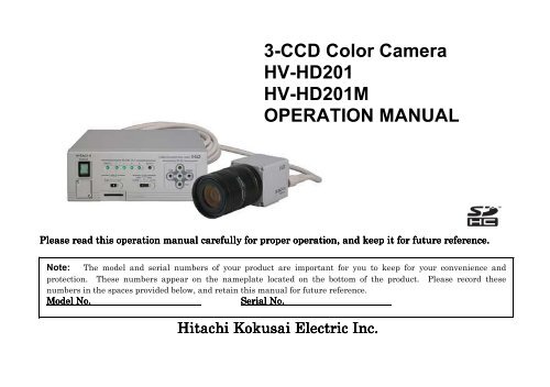
3-CCD Color Camera<br />
<strong>HV</strong>-<strong>HD201</strong><br />
<strong>HV</strong>-<strong>HD201</strong>M<br />
OPERATION MANUAL<br />
Please read this operation manual carefully for proper operation, and keep it for future reference.<br />
Note: The model and serial numbers of your product are important for you to keep for your convenience and<br />
protection. These numbers appear on the nameplate located on the bottom of the product. Please record these<br />
numbers in the spaces provided below, and retain this manual for future reference.<br />
Model No. Serial No.<br />
<strong>Hitachi</strong> <strong>Kokusai</strong> <strong>Electric</strong> Inc.
IMPORTANT SAFETY INSTRUCTIONS<br />
1. Read Instructions<br />
All the safety and operating instructions should<br />
be read before the product is operated.<br />
2. Retain Instructions<br />
The safety and operating instructions should be<br />
retained for future reference.<br />
3. Heed Warnings<br />
All warnings on the product and the operating<br />
instructions should be adhered to.<br />
4. Follow Instructions<br />
All operating and use instructions should be<br />
followed.<br />
5. Cleaning<br />
Unplug this product from the wall outlet before<br />
cleaning. Do not use liquid cleaners or aerosol<br />
cleaners. Use a damp cloth for cleaning.<br />
6. Attachments<br />
Do not use attachments not recommended by the<br />
product manufacturer as they may cause<br />
hazards.<br />
7. Water and Moisture<br />
Do not use this product near water - for example,<br />
near a bath tub, wash bowl, kitchen sink, or<br />
laundry tub; in a wet basement; or near a<br />
swimming pool; and the like.<br />
8. Accessories<br />
Do not place this product on an unstable cart,<br />
stand, tripod, bracket, or table. The product may<br />
fall, causing serious injury to a child or adult, and<br />
serious damage to the product. Use only with a<br />
cart, stand, tripod, bracket, or table recommended<br />
by the manufacturer, or sold with the product.<br />
Any mounting of the product should follow the<br />
manufacturer's instructions, and should use a<br />
mounting accessory recommended by the<br />
manufacturer.<br />
9. Moving<br />
A product and cart combination should be moved<br />
with care.<br />
Quick stops, excessive force, and uneven surfaces<br />
may cause the product and cart combination to<br />
overturn.<br />
10. Ventilation<br />
Slots and openings in the cabinet are provided for<br />
ventilation and to ensure reliable operation of the<br />
product and to protect it from overheating, and<br />
these openings must not be blocked or covered.<br />
The openings should never be blocked by placing<br />
the product on a bed, sofa, rug, or other similar<br />
surface. This product should not be placed in a<br />
A
uilt-in installation such as a bookcase or<br />
rack unless proper ventilation is provided or the<br />
manufacturer's instructions have been adhered<br />
to.<br />
11. Power Sources<br />
This product should be operated only from the<br />
type of power source indicated on the marking<br />
label. If you are not sure of the type of power<br />
supply to your home, consult your product dealer<br />
or local power company. For products intended<br />
to operate from battery power, or other sources,<br />
refer to the operating instructions.<br />
12. Grounding or Polarization<br />
This product is equipped with a three-wire<br />
grounding-type plug a plug having a third<br />
(grounding) pin. This plug will only fit into a<br />
grounding-type power outlet. This is a safety<br />
feature. If you are unable to insert the plug into<br />
the outlet, contact your electrician to replace your<br />
obsolete outlet. Do not defeat the safety purpose<br />
of the grounding-type plug.<br />
13. Power-Cord Protection<br />
Power-supply cords should be routed to that they<br />
are not likely to be walked on or pinched by items<br />
placed upon or against them, paying particular<br />
attention to cords at plug, convenience<br />
receptacles, and the point where they exit from<br />
the product.<br />
14. Lightning<br />
For added protection for this product during a<br />
lightning storm, or when it is left unattended and<br />
unused for long periods of time, unplug it from<br />
the wall outlet. This will prevent damage to the<br />
product due to lightning and power-line surges.<br />
15. Overloading<br />
Do not overload wall outlets, extension cords or<br />
integral convenience receptacles as this can result<br />
in a risk of fire or electric shock.<br />
16. Object and Liquid Entry<br />
Never push objects of any kind into this product<br />
through openings as they may touch dangerous<br />
voltage points or short-out parts that could result<br />
in a fire or electric shock. Never spill liquid of<br />
any kind on the product.<br />
17. Inflammable and Explosive Substance<br />
Avoid using this product where there are gases,<br />
and also where there are inflammable and<br />
explosive substances in the immediate vicinity.<br />
18. Heavy Shock or Vibration<br />
When carrying this product around, do not subject<br />
the product to heavy shock or vibration.<br />
B
19. Servicing<br />
Do not attempt to service this product yourself as<br />
opening or removing covers may expose you to<br />
dangerous voltage or other hazards. Refer all<br />
servicing to qualified service personnel.<br />
20. Damage Requiring Service<br />
Unplug this product from the wall outlet and<br />
refer servicing to qualified service personnel<br />
under the following conditions:<br />
a.When the power-supply cord or plug is<br />
damaged.<br />
b.If liquid has been spilled, or objects have fallen<br />
into the product.<br />
c. If the product has been exposed to rain or<br />
water.<br />
d.If the product does not operate normally by<br />
following the operating instructions. Adjust<br />
only those controls that are covered by the<br />
operating instructions as an improper<br />
adjustment of other controls may result in<br />
damage and will often require extensive work<br />
by a qualified technician to restore the product<br />
to its normal operation.<br />
e. If the product has been dropped or damaged in<br />
any way.<br />
f. When the product exhibits a distinct change in<br />
performance-this indicates a need for service.<br />
21. Replacement Parts<br />
When replacement parts are required, be sure the<br />
service technician has used replacement parts<br />
specified by the manufacturer or have the same<br />
characteristics as the original part.<br />
Unauthorized substitutions may result in fire,<br />
electric shock, or other hazards.<br />
22. Safety Check<br />
Upon completion of any service or repairs to this<br />
product, ask the service technician to perform<br />
safety checks to determine that the product is in<br />
proper operating condition.<br />
23. Wall or Ceiling Mounting<br />
The product should be mounted to a wall or<br />
ceiling only as recommended by the<br />
manufacturer.<br />
24. Heat<br />
The product should be situated away from heat<br />
sources such as radiators, heat registers, stoves,<br />
or other products (including amplifiers) that<br />
produce heat.<br />
C
WICHTIGE SICHERHEITSANWEISUNGEN<br />
1. Alle Anweisungen lesen<br />
Vor Betrieb des Erzeugnisses sollten alle<br />
Sicherheits-und Bedienungsanleitungen gelesen<br />
werden.<br />
2. Die Anweisungen aufbewahren<br />
Die Sicherheits-und Bedienungsanleitungen<br />
sollten fünftigen Bezug aufbewahrt werden.<br />
3. Warnungen beachten<br />
Die Warnungen auf dem Erzeugnis und in den<br />
Bedienungsanleitungen solten beachtet werden.<br />
4. Anweisungen befolgen<br />
Alle Bedienungsanleitung-und<br />
Verwendungsanweisungen sollten befolgt werden.<br />
5. Reinigung<br />
Den Stecker des Geräts vor Reinigung aus der<br />
Steckdose ziehen. Keine flüssigen Reinigungsmittel<br />
oder Aerosolreiniger verwenden. Zum Reinigen<br />
einen feuchten Lappen verwenden.<br />
6. Zubehör<br />
Nur vom-Hersteller des Erzeugnisses empfohlenes<br />
Zubehör verwenden, da es sonst zu Störungen<br />
kommen kann.<br />
7. Wasser und Feuchtigkeit<br />
Dieses Erzeugnis nicht in der Nähe von Wasser<br />
verwenden - z.B, in der Nähe einer Badewanne,<br />
eines Waschbeckens, einer Küchenspüle, eines<br />
D<br />
Waschzubers, in einem nassen Keller, in der Nähe<br />
eines Schwimmbeckens usw.<br />
8. Aufstellung<br />
Das Erzeugnis nicht auf einen unstabilen Wagen,<br />
Stand, Dreifuß, Träger oder Tisch stellen.<br />
Das Erzeugnis kann sonst herunterfallen und ein<br />
kind oder einen Erwachsenen schwer verietzen.<br />
Außerdem kann das Gerät schwer beschädigt<br />
werden. Nur mit einem Wagen, Stand, Dreifuß,<br />
Träger oder Tisch verwenden, der vom Hersteller<br />
empfohlen oder mit dem Erzeugnis verkauft<br />
worden ist. Für jegliche Anbringung sollten die<br />
Anweisungen des Herstellers befolgt werden, und<br />
das vom Hersteller empfohlene Anbringungszubehör<br />
sollte verwendet werden.<br />
9. Eine Kombination von Erzeugnis und Wagen<br />
sollte vorsichtig bewegt werden<br />
Schneller Halt, übermäßige Krafteinwirkung und<br />
unebene Oberflächen können Umkippen der<br />
kombination von Erzeugnis und Wagen<br />
verursachen.<br />
10. Ventilation<br />
Schlitze und Öffnungen im Gehäuse dienen der<br />
Ventilation. Sie sind für zuverlässigen Betrieb<br />
des Gerätes und Schutz vor Überhitzung
erforderlich und dürfen nicht blockiert oder abgedeckt<br />
werden.<br />
Die Öffnungen sollten niemals dadurch blockiert<br />
werden, daß, das Gerät auf ein Bett, ein Sofa,<br />
einen Teppich oder eine ähnliche Oberfläche<br />
gestellt wird.<br />
Das Gerät sollte nur dann in Einbauinstallierung<br />
wie in einem Bücherschrank oder einem Gestell<br />
verwendet werden, wenn angemessene<br />
Ventilation vorgesehen ist bzw. Die<br />
Anweisungen des Herstellers befolgt worden<br />
sind.<br />
11. Stromversorgung<br />
Dieses Erzeugnis sollte nur an der auf dem<br />
Typenschild angegebenen Stromversorgungsart<br />
betrieben werden. Wenn Sie nicht sicher sind,<br />
was für eine Stromversorgung Sie haben, so<br />
wenden Sie sich bitte an Ihren Erzeugnishändler<br />
oder an das lokale Elektrizitätswerk. Beziehen<br />
Sie sich für Batteriebetrieb oder andere<br />
Stromquellen vorgesehene Erzeugnisse bitte auf<br />
die Bedienungsanleitungen.<br />
12. Erdung oder Polarisierung<br />
Dieses Erzeugnis ist mit einem<br />
Schutzkontaktstecker mit drei Leitern ausgerüstet,<br />
mit einem Erdungskontakt. Dieser Stecker paßt<br />
nur in ein schuko-Steckdose. Dies ist eine<br />
Sicherheitsmaßnahme. Wenn Sie den Stecker<br />
nicht in die Steckdose stecken können, so wenden<br />
Sie sich bitte an ihren Elektriker, damit er die<br />
veraltete Schuts des Schutzkontaktsteckers<br />
unwirksam.<br />
13. Netzkabelschutz<br />
Netzkabel sollten so verlegt werden, deß möglichst<br />
nicht darauf getreten wird und daß sie nicht<br />
eingeklemmt werden, mit besonderer Beachtung<br />
der kabel an Stackern, Verlängerungskabeln und<br />
dem Austritt des Kabels aus dem Erzeugnis.<br />
14. Blitzschlag<br />
Für zusätzlichen Schutz des Erzeugnisses während<br />
eines Gewitters oder bei Nichtverwendung für<br />
lange Zeit den Stecker aus der Steckdose ziehen.<br />
Dies verhütet Beschädigung durch Blitzschlag und<br />
Netzspannungsstöße.<br />
15. Überlastung<br />
Wandsteckdosen, Verlängerungskabel und<br />
eingebaute Bequemlickkeitssteckdosen nicht<br />
überlasten, da dies Feuer oder elektrischen Schlag<br />
verursachen kann.<br />
E
16. Eindringen von Fremdkörpern und Flüssigkeit<br />
Niemals Objekte irgendwelcher Art durch die<br />
Öffnungen in das Gerät schieben, da diese unter<br />
hoher Spannung stehende Teile berühren oder<br />
kurzschließen können, wodurch es zu Feuer oder<br />
elektrischem Schlag kommen kann. Niemals<br />
Flüssigkeiten irgendwelcher Art auf das<br />
Erzeugnis verschütten.<br />
17. Entflammbare und explosive Substanzen<br />
Vermeiden Sie Verwendung dieses Erzeugnisses<br />
an Orten mit Gasen bzw. entflammbaren oder<br />
explosiven Substanzen in der direkten<br />
Umgebung.<br />
18. Starke stöße oder Vibrationen<br />
Setzen Sie das Erzeugnis beim Transport nicht<br />
starken Stößen oder Vibrationen aus.<br />
19. Wartung<br />
Versuchen Sie nicht, dieses Erzeugnis Selbst zu<br />
warten, da Sie sich durch Öffnen bzw.<br />
Entfernen von Abdeckungen hohen Spannungen<br />
und sonstigen Gefährdungen ausserzen können.<br />
Beziehen Sie sich für jegliche Wartung auf<br />
qualifiziertes Wartungspersonal.<br />
20. Beschädigung, die Wartung erfordert<br />
Ziehen Sie den Stecker dieses Erzeugnisses aus<br />
der Steckdose und wenden Sie sich an<br />
qualifiziertes Wartungspersonal, wenn eine der<br />
folgenden Bedingungen vorliegt:<br />
a. Wenn das Netzkabel oder der Stecker<br />
beschädigt ist.<br />
b. Bei Eindringen von Flüssigkeit oder<br />
Fremdkörpern in das Gerät.<br />
c. Wenn das Erzeugnis Regen oder Wasser<br />
ausgesetzt worden ist.<br />
d. Wenn das Erzeugnis bei Befolgen der<br />
Bedienungsanleitungen nicht normal<br />
funktioniert.<br />
Nur die Regelelemente verstellen, die in den<br />
Bedienungsanleitungen behandelt werden, da<br />
unangemessene Einstellung anderer<br />
Regelelemente Beschädigung verursachen kann<br />
und oft beträchtliche Arbeit durch einen<br />
qualifizierten Techniker erfordert, um das<br />
Erzeugnis wieder, zu normalem Betrieb<br />
zurückzubringen.<br />
e. Wenn das Erzeugnis fallen gelassen oder<br />
beschädigt worden ist.<br />
f. Wenn das Erzeugnis eine klare Änderung in<br />
der Leistung zeigt-dies weist darauf hin, daß<br />
Wartung erforderlich ist.<br />
F
21. Ersatzteile<br />
Wenn Ersatzteile erforderlich sind, darauf achten,<br />
daß der Wartungstechniker nur die vom<br />
Hersteller festgelegten Ersatzteile oder Teile mit<br />
den gleichen Charakteristiken wie die<br />
ursprünglichen Teile verwendet. Unautorisierte<br />
Ersatzteile können Feuer, elektrischen Schlag<br />
oder sonstige Gefährdungen verursachen.<br />
22. Sicherheitsprüfung<br />
Bitten Sie den Wartungstechniker nach der<br />
Vollendung von Wartung oder Reparaturarbeiten<br />
an diesem Erzeugnis um die Durchführung von<br />
Sicherheitsprüfungen, um zu bestimmen, daß das<br />
Erzeugnis im angemissenen Betriebszustand ist.<br />
23. Anbringung an der Wand oder an der Decke<br />
Das Erzeugnis sollte nur entsprechend den<br />
Empfehlungen des Herstellers an einer Wand<br />
oder an der Decke angebracht werden.<br />
24. Wärme<br />
Das Erzeugnis sollte fern von Wärmequellen wie<br />
Radiatoren, Heizwiderständen, Öfen und anderen<br />
Wärme erzeugenden Erzeugnissen (einschließlich<br />
Verstärkern) aufgestellt werden.<br />
G
MISES EN GARDE IMPORTANTES<br />
1. Lire les instructions<br />
Lire toutes les instructions de sécurité et de<br />
fonctionnement avant de faire fonctionner<br />
l’appareil.<br />
2. Conserver ces instructions<br />
Conserver les instructions de sécurité et de<br />
fonctionnement á des fins de référence ultérieure.<br />
3. Tenir compte des avertissements<br />
Tous les avertissements qui figurent sur<br />
l’appareil et dans le mode d’emploi devront être<br />
respectés.<br />
4. Observer les instructions<br />
Observer toutes les instructions de<br />
fonctionnement et d’utilisation.<br />
5. Nettoyage<br />
Avant de procéder au nettoyage, débrancher<br />
l’appareil de la prise secteur. Ne pas utiliser<br />
de produits de nettoyage liquides ou en aérosol.<br />
Nettoyer l’appareil avec un chiffon humide.<br />
6. Fixations<br />
Ne pas utiliser de fixations non recommandées<br />
par le fabricant de l’appareil car elles<br />
pourraient être source de danger.<br />
7. Eau et humidité<br />
Ne pas utiliser l’appareil á proximité d’eau-ar exemple<br />
prés d’une baignoire, d’un lavabo, d’un évier ou<br />
d’un bac á lessive, dans un sous-sol humide, ou<br />
prés d’une piscine, etc.<br />
8. Accessoires<br />
Ne pas placer l’appareil sur un chariot, un socle,<br />
un pied, un support ou one table instables<br />
L’appareil pourrait tomber, blessant griévement<br />
des enfants ou des adultes, et étant sérieusement<br />
endommagé.<br />
Utiliser exclusivement le chariot, le socle, le pied,<br />
le support ou la table recommandés par le<br />
fabricant, ou vendus avec l’appareil. Pour tout<br />
montage de l’appareil, respecter les instructions<br />
du fabricant, et utiliser á cette fin l’accessoire de<br />
montage recommandé par le fabricant.<br />
9. L’appareil monté sur son chariot devra être<br />
déplacé avec précaution<br />
Des arrêts brusques, une force excessive et des<br />
surfaces irréguliéres pourraient provoquer le<br />
renversement de l’ensemble appareil-chariot.<br />
10. Ventilation<br />
Les fentes et les ouvertures du coffret sont<br />
prévues pour la ventilation ainsi que pour<br />
garantir un fonctionnement en toute sécurité de<br />
H
l’appareil et le protéger de toute surchauffe, et<br />
ces ouvertures ne devront donc être ni<br />
obstruées ni recouvertes. Ne jamais obstruer les<br />
ouvertures en placant l’appareil sur un lit, un<br />
sofa, un tapis ou toute surface similaire. Ne<br />
jamais placer l’appareil dans un support confiné,<br />
par exemple une bibliothéque ou une é tagé re,<br />
sans ventilation suffisante ou sans repecter les<br />
instructions du fabricant.<br />
11. Sources d’allmentation<br />
L’appareil devra être alimenté exclusivement sur<br />
le type d’alimentation indiqué sur l’étiquette<br />
signalétique. Sil’on n’est pas sûr du type<br />
d’alimentatio du local, consulter le revendeur de<br />
l’appareil ou la compagnie d’électricité locale.<br />
Pour les appareils qui fonctionnent sur batterie<br />
ou sur d’autres sources, voir le mode d’emploi.<br />
12. Mise á la terre ou polarisation<br />
L’appareil est doté d’une fiche trifilaire avec mise<br />
á la terre, dont la troisiéme broche assure la mise<br />
á la terre. Cette fiche ne rentrera que dans les<br />
prises trifilaires de mise á la terre. Ceci est une<br />
mesure de sécurité. Si la fiche ne rentre pas<br />
dans la prise, faire remplacer la prise désuéte par<br />
un électricien.<br />
Ne pas rendre vaine la measure de sécurité<br />
assurée par cette prise avec mise á la terre.<br />
13. Protection du cordon d’alimentation<br />
Acheminer les cordons d’alimentation de facon<br />
qu’on ne risque pas de marcher dessus ou de les<br />
coincer sous un objet placé dessus ou contre eux.<br />
Faire particuliérement attention aux fiches des<br />
cordons, á la proximité des prises, et á l’endroit oú<br />
ils ressortent de l’appareil.<br />
14. Foudre<br />
Pour renforcer la protection de l’appareil pendant<br />
un orage, ou si l’on s’en éloigne ou qu’on reste<br />
longtemps sans l’utiliser, le débrancher de la<br />
source d’alimentation. Ceci permettra d’éviter<br />
tout dommage de l’appareil dú á la foudre et aux<br />
surtensions de ligne.<br />
15. Surcharge<br />
Ne pas surcharger les prises, rallonges et prises<br />
multiples car cela pourrait entraîner un risque de<br />
feu ou de choc électrique.<br />
16. Pénétration d’objets et de liquides<br />
Ne jamais enfoncer d’objets d’aucune sorte dans<br />
les ouvertures de l’appareil car ils pourraient<br />
toucher des points de tension dangereuse ou<br />
court-circuiter des piéces, ce qui pourrait<br />
I
provoquer un feu ou un choc électrique. Ne<br />
jamais renverser de liquide d’aucune sorte sur<br />
l’appareil.<br />
17. Substances inflammabes et explosives<br />
Eviter d’utiliser l’appareil en présence de gaz,<br />
ainsi qu’á proximité immédiate de substances<br />
inflammables et explosives.<br />
18. Chocs ou vibrations violents<br />
Lorsqu’on transporte l’appareil, ne pas le<br />
soumettre á des chocs ou des vibrations violents.<br />
19. Réparations<br />
Ne pas tenter de réparer l’aapareil soi-même car<br />
le fait d’ouvrir ou de retirer les caches risque<br />
d’exposer l’utilisateur á des tensions dangereuses<br />
notamment. Confier toute réparation á un<br />
personnel qualifié.<br />
20. Dommages nécessitant réparations<br />
Débrancher l’appareil de la source d’alimentation<br />
et confier les réparations á un personnel qualifié<br />
dans les cas suivants:<br />
a. Lorsque le cordon d’alimentation ou sa fiche<br />
sont endommagés<br />
b. Si du liquide s’est renversé sur l’appareil ou<br />
que des objets sont tombés dedans<br />
c. Si l’appareil a été exposé á la pluie ou á l’eau.<br />
d. Si l’appareil ne fonctionne pas normalement<br />
lorsqu’on observe les instructions d’utilisation.<br />
Ne régler que les commandes couvertes par le<br />
mode d’emploi ; en effet, un réglage incorrect<br />
des autres commandes pourrait entrainer des<br />
dommages et nécessiteront souvent des travaux<br />
de réparation coûteux par un technicien qualifié<br />
pour remettre l’appareil en état de marche.<br />
e. Si l’appareil est tombé ou qu’il a été<br />
endommagé.<br />
f. Si l’appareil affiche une nette modification de<br />
ses performances, cela signifie qu’il a besoin<br />
d’être réparé.<br />
21. Piéces de rechange<br />
Si l’on a besoin de piéces de rechange, veiller á ce<br />
que le technicien de réparation utilise<br />
exclusivement les piéces de rechange spécifiées<br />
par le fabricant ou des piéces ayant les mêmes<br />
caractéristiques que les piéces d’origine. Les<br />
piéces de rechange non autorisées risquent de<br />
provoquer un feu, un choc électrique et autres<br />
dangers.<br />
J
22. Vérificaton de sécurité<br />
Aprés tout travail d’entretien ou de réparation de<br />
l’appareil, demander au technicien de réparation<br />
d’effectuer les vérifications de sécurité pour<br />
s’assurer que l’appareil est en bon état de<br />
marche.<br />
23.Montage au mur ou au plafond<br />
L’appareil ne pourra être monté au mur ou au<br />
plafond que de la maniére recommandée par le<br />
fabricant.<br />
24. Chaleur<br />
Eloigner l’appareil des sources de chaleur, telles<br />
que radiateurs, appareils de chauffage,<br />
cuisiniéres, et de tour produit engendrant de la<br />
chaleur (y compris les amplificateurs).<br />
K
IMPORTANT NOTICE<br />
For USA<br />
These products have been tested and found to<br />
comply with the limits for a Class A digital<br />
device, pursuant to Part 15 of the FCC Rules.<br />
These limits are designed to provide<br />
reasonable protection against harmful<br />
interference when the equipment is operated<br />
in a commercial environment. This<br />
equipment generates, uses, and can radiate<br />
radio frequency energy and, if not installed<br />
and used in accordance with the instruction<br />
manual, may cause harmful interference to<br />
radio communications. <strong>Op</strong>eration of this<br />
product in a residential area is likely to cause<br />
harmful interference in which case the user<br />
will be required to correct the interference at<br />
his own expense.<br />
WARNING<br />
Changes or modifications not expressly<br />
approved by <strong>Hitachi</strong> <strong>Kokusai</strong> <strong>Electric</strong><br />
responsible for compliance could void the<br />
user’s authority to operate the equipment.<br />
For Canada<br />
This product does not exceed the class A/class<br />
B limits for radio noise emissions from digital<br />
apparatus as set out in the radio interference<br />
regulations.<br />
Le présent appareil n’émet pas de bruits<br />
radioélectriques dépassant les limités<br />
applicable aux appareils numériques de classe<br />
A prescrites dans le rVglement sur le<br />
brouillage radioélectrique édicter par le<br />
ministére des communications du canada.<br />
L
Table of contents<br />
IMPORTANT SAFETY INSTRUCTUIONS A<br />
IMPORTANT NOTICEL<br />
Table of contents M<br />
Standard composition 1<br />
Overview 1<br />
Features 2<br />
Notes to users 3<br />
Name and function of each section 5<br />
Lens 7<br />
Lens selection 7<br />
Flange Back adjustment 8<br />
Video signal type lens adjustment 9<br />
System configuration example 10<br />
Menu Screen <strong>Op</strong>eration 11<br />
Menu Structure 11<br />
MAIN MENU 14<br />
GAIN/SHUTTER 16<br />
DETAIL 19<br />
ALC 20<br />
AUTO SETUP 23<br />
SPECIAL SET 24<br />
FILE SET 25<br />
FILE NAME SET 26<br />
SD CARD 27<br />
LEVEL 28<br />
MASKING 29<br />
GAMMA/KNEE 33<br />
DETAIL 35<br />
COLOR DETAIL 37<br />
AUTO WHITE 38<br />
SYSTEM 40<br />
ID/TITLE 43<br />
LENS 45<br />
OTHER FUNCTION 47<br />
TIME/DATE 48<br />
How to Attain Better images 49<br />
Black Balance Adjustment 49<br />
White Balance Adjustment 50<br />
Real time Auto White 52<br />
Auto Shading Correction 53<br />
ALC (Auto level control) 54<br />
RC-Z3 remote control panel 55<br />
RC-Z3 panel facilities 56<br />
Menu screen composition 62<br />
Connectors 63<br />
External synchronization 66<br />
Specifications 67<br />
Input/Output Signals 69<br />
Major accessories 71<br />
Dimensions 71<br />
M
Standard composition<br />
Check when unpacking.<br />
Camera head 1<br />
Camera control unit 1<br />
Camera cable(5.5m) 1<br />
Power plug(RM12BPG-3S(JMR0152 * ), for 12V IN) 1<br />
Replacement fuse(MT4-5A(250V-5A UL)(EGF0713) * ) 1<br />
Replacement fuse(MT4-1A(250V-1A UL, CSA)(EFL0175) * ) 1<br />
<strong>Op</strong>eration <strong>Manual</strong> 1<br />
* Part code<br />
Overview<br />
The <strong>Hitachi</strong> color camera <strong>HV</strong>-<strong>HD201</strong> is 3CCD<br />
HDTV camera combining high picture quality<br />
and high stability with the convenience of C<br />
mount optics. CCD size is 1/2-size and each<br />
consists of 1,500,000 picture elements.<br />
Signal processing is all digitalized.<br />
High quality picture and high color<br />
reproducibility functions are attained by<br />
<strong>Hitachi</strong>'s unique digital processing technology<br />
and the latest CCD. In addition to the digital<br />
output of high-definition signal of four modes of<br />
1080i/59.94, 1080i/50, 720p/59.94, 720p/50, it<br />
provides the VBS and RGB/YPbPr analog signal<br />
output of 480i/59.94(NTSC) and 576i/50(PAL)<br />
format. The image can be used all over the world.<br />
1
Features<br />
C mount<br />
The camera uses a C mount lens, which is the de<br />
facto standard in the industry. It allows use with<br />
different types of optical systems.<br />
Note : We recommend using a HDTV lens for<br />
obtaining full performance from the camera.<br />
Multiple Formats<br />
HDTV : There are 4 video output modes. These<br />
modes are 1080i(59.94 fields or 50 fields) or<br />
720p(59.94 frames or 50 frames).<br />
SDTV : Video output modes are 576i(50 fields) or<br />
480i(59.94 fields).<br />
Bi-directional data communication<br />
The camera can be connected to a personal<br />
computer via RS-232C for two-way data<br />
communications to provide finely detailed camera<br />
control. An identification (ID) code can be<br />
assigned to each camera in a system and allow<br />
remotely controlling multiple cameras from a<br />
single computer.<br />
There are total 8 HDTV/SDTV video output<br />
modes.<br />
Note : The SDI output supports only HDTV.<br />
Auto shading compensation (ASC)<br />
Color shading incurred when using a C mount<br />
lens is automatically compensated (attenuated).<br />
Two modes of shading are provided and can be<br />
selected according to the cameras application, a<br />
vertical color shading mode or a two-dimensional<br />
luminance-shading mode.<br />
2
Notes to users<br />
Important safety notes<br />
Use this camera with a 12 VDC power supply.<br />
Observe that flammable objects, water or metal<br />
do not enter the camera interior. These may<br />
lead to failure or accident.<br />
Do not modify the camera or use the camera with<br />
external covers removed. These may cause<br />
failure, void any warranties and pose a safety<br />
hazard.<br />
Stop using the camera at the approach of an<br />
electrical storm (thunder audible). Protect the<br />
camera from rain if using it outdoors.<br />
In event the camera shows any abnormality,<br />
switch off the camera and disconnect the power<br />
cord. Contact a <strong>Hitachi</strong> <strong>Kokusai</strong> <strong>Electric</strong> service<br />
representative.<br />
<strong>Op</strong>erating considerations<br />
Power supply<br />
Check that the supplied voltage is between 10.5<br />
and 15 VDC. Inadequate voltage can affect color<br />
fidelity and cause noise, while voltage over 15 V<br />
can damage the camera.<br />
Connectors<br />
Confirm the power is off before connecting or<br />
disconnecting a signal cable. Grasp connectors<br />
by the body, not the attached wires.<br />
Lens<br />
The correct lens is important for deriving<br />
optimum performance from the camera. Consult<br />
a <strong>Hitachi</strong> <strong>Kokusai</strong> <strong>Electric</strong> dealer for a selection<br />
of fine lenses according to the application.<br />
Installation and storage sites<br />
The following types of environment can impair<br />
performance, lead to damage, pose safety hazards<br />
and shorten the useful life of the camera. Select<br />
the sites for installing the storing the camera<br />
carefully.<br />
• Direct sunlight, rain or snow<br />
• Flammable or corrosive gasses<br />
• Very hot or cold (beyond 0 to 40 ℃ operating,<br />
-20 to 60 ℃ storage)<br />
• Humid or dusty<br />
• Exposed to vibration or shock<br />
• Strong electrical or magnetic fields<br />
• Exceptionally strong light<br />
Continuous operation<br />
In situations where the camera is used<br />
continuously for long periods of time, the ambient<br />
temperature should be kept below 40 ℃ in order<br />
to avoid accelerated deterioration of internal<br />
parts and to derive maximum long-term<br />
reliability.<br />
3
Cleaning<br />
A photographer’s blower or lens brush can be<br />
used for clearing dust from the lens and optical<br />
filters.<br />
Wipe dust from the case with a soft dry cloth. If<br />
soiling is severe, moisten the cloth with a<br />
solution of neutral detergent. Afterwards, wipe<br />
the cover with a dry cloth.<br />
Do not use petroleum distillates, alcohol or spray<br />
type cleaners.<br />
Blinking Screen at AUTO BLACK<br />
It is not abnormal operation through the screen<br />
might blinks at the power start up or execution of<br />
AUTO BLACK.<br />
Transportation<br />
Remove the lens (install lens mount cap) and<br />
other attachments. Pack the camera carefully<br />
in its original or equivalent container. Use<br />
ample cushioning to protect the camera from<br />
physical shock.<br />
Trademarks<br />
SDHC logo is trademark.<br />
HDMI and High-Definition Multimedia Interface are either registered trademarks or trademarks of<br />
HDMI Licensing LLC.<br />
4
Name and function of each section<br />
5
It sets the operational mode of HDTV.<br />
Please change it at power off state.)<br />
<br />
Please change it at power off state.)<br />
Outputs HD-SDI signal.<br />
Outputs Y/C signal.<br />
Outputs VBS signal.<br />
Inputs SYNC signal of HDTV for external<br />
synchronization.<br />
The camera cable linked to a camera head<br />
is connected.<br />
<br />
<br />
<br />
Used for connection with the remote<br />
control box RC-Z3 or personal computer<br />
to remote control the camera.<br />
<br />
<br />
<br />
<br />
O u t p u t s t h e a n a l o g p i c t u r e<br />
signal/synchronization signal.<br />
(Please refer to the connector terminal<br />
figure for details.<br />
The 12V power supply is connected.<br />
Sets the signal level to connect to<br />
REMOTE terminal. (Please set it to <br />
-3 when camera is connected with<br />
r e m ot e c o nt r o l b o x m a d e b y o ur<br />
company.)<br />
It inputs or outputs the HD/VD signal<br />
o f m u l t i c o n n e c t o r f o r e x t e r n a l<br />
synchronization.<br />
Connects the iris connector of an auto<br />
iris lens.<br />
Outputs the HDTV picture signal.<br />
6
Lens<br />
CAUTION<br />
Observe the dimensions of the lens mounting<br />
selection as illustrated at the right.<br />
If the dimensions are not observed, do not use<br />
such a lens, because the lens and the camera<br />
will be damaged.<br />
Flange surface of lens<br />
Lens selection<br />
1) <strong>Op</strong>tical characteristics<br />
The proper lens is vital for obtaining full<br />
performance from the camera. The exit pupil<br />
distance is particularly important for a 3CCD<br />
type camera. If too short, vertical color<br />
shading can appear in the picture.<br />
Also, as the lens iris approaches fully open,<br />
problems such as loss of resolution, shading<br />
and flare (overall image "white-out") can<br />
detract from picture quality. When using in<br />
applications that call for open iris, the lenses<br />
for 3CCD are recommended. If another lens is<br />
contemplated, check the performance<br />
beforehand.<br />
4.0mm or less<br />
2) Auto iris lens<br />
Main types are Video (with self contained iris<br />
amplifier) and DC (DC voltage applied to open<br />
lens iris) and manual over-ride (e.g. Cosmicar).<br />
Lenses without self-contained iris amplifier are<br />
not compatible.<br />
Camera settings differ according to the auto iris<br />
lens type (see page 45).<br />
Note: The <strong>HV</strong>-<strong>HD201</strong> uses lens connector wiring<br />
prescribed by the EIAJ (Electronic Industries<br />
Association of Japan). Refer to page 64.<br />
7
3) Flangeback adjustment of zoom lens<br />
1) Set the lens to telephoto and pickup an<br />
image more than 3 meters distant. Turn<br />
the focus ring to adjust the focus.<br />
2) Set the lens to wide angle and while taking<br />
care not to disturb the focus ring, turn the<br />
flangeback adjustment ring to adjust the<br />
focus.<br />
Repeat the above steps until focus is<br />
obtained at both the telephoto and wide<br />
angle ends.<br />
8
Video signal type lens adjustment<br />
Adjustment is required after replacing the lens or<br />
if using the camera for the first time.<br />
1) Preparation<br />
(1) If GAIN SW of camera is at AGC.<br />
(a) Set GAIN SW to another mode.<br />
(b) Set the CAMERA MODE to MANUAL.<br />
(c) Set the SHUTTER of GAIN/SHUTTER<br />
menu to mode other than AES.<br />
(2) If the light source has a flicker component<br />
(e.g. fluorescent or mercury light), change<br />
the electronic shutter mode (SHUTTER or<br />
SHUTTER VAR. setting) to reduce the<br />
flicker.<br />
2) Adjustment<br />
Hold the U button depressed and press Setup for<br />
about 2 seconds to display the Special Set menu.<br />
LENS<br />
LENS TYPE :VIDEO<br />
* IRIS MODE :---<br />
* IRIS SPEED :---<br />
* OPEN LIMIT :---<br />
* CLOSE LIMIT :---<br />
IRIS GAIN : 0<br />
L H<br />
INITILIZE :[PUSH L+R] 2SEC<br />
Video level indicator<br />
Change to the Lens screen and check the LENS<br />
TYPE setting. If DC, change this to Video.<br />
(1) Set the lens ALC control fully toward the<br />
average (Av ) position.<br />
(2) Capture the subject(such as white paper)<br />
where relatively brightness does not change<br />
and adjust the lens level control to where the<br />
center quadrangle is positioned at the video<br />
signal level indicator cross mark.<br />
(3) If auto iris hunting occurs, reduce the Iris Gain<br />
setting.<br />
3) Lens adjustment difficulties<br />
(1) If the light intensity level of subject is low in<br />
auto iris operation, adjust it by setting GAIN<br />
SW and increasing the GAIN setting of<br />
GAIN/SHUTTER menu.<br />
(2) Lens Level control fully at Hi, but auto iris<br />
inoperative. Reduce the Iris Gain setting or<br />
Lens Level control fully at Low, but auto iris<br />
inoperative Increase the Iris Gain setting.<br />
Note: The video signal level indicator sensitivity is<br />
high in order to increase lens adjustment accuracy.<br />
<strong>Op</strong>erate the lens Level control slowly.<br />
.<br />
9
System configuration example<br />
HD-SDI<br />
HD-TV monitor<br />
VBS<br />
SD-TV monitor<br />
AC adapter<br />
IA-60a<br />
Camera control box<br />
RC-Z3<br />
Y/G<br />
Pb/B<br />
Pr/R<br />
RS-<br />
232C<br />
Video capturing/Control<br />
PC<br />
Frame grabber board<br />
10
Menu Screen <strong>Op</strong>eration<br />
1. Menu Structure<br />
For settings in the camera, the MAIN and SPECIAL SET menus are available.<br />
1) MAIN Menu Structure<br />
Press the MENU button and MAIN MENU appears on the screen to indicate the main menu mode. Again<br />
press the MENU button to extinguish the menu and to enter in the direct mode. There are a main function<br />
setup menu and four sub-menus, which are arranged hierarchically as shown below. On the MAIN MENU,<br />
move the cursor to item with and press the R button, the desired subsidiary menu will be displayed. To<br />
return to the MAIN MENU from the subsidiary menu, move the cursor to the top line (title line of<br />
subsidiary menu) and press the L button.<br />
On each menu screen, move the cursor to any desired item using the U or D button. For mode change/data<br />
setting, use the L or R button.<br />
MAIN MENU [ FILE1 ]<br />
CAMERA MODE :MANUAL<br />
WHITE BALANCE :MEMORY( 4400K)<br />
MASTER SAT. : 0<br />
MASTER BLACK : 0<br />
GAIN/SHUTTER :<br />
DETAIL :<br />
ALC :<br />
AUTO SETUP :<br />
FILE SELECT:FILE1<br />
GAIN/SHUTTER [ FILE1 ]<br />
[GAIN] :NORM<br />
NORM :+ 0 dB<br />
HIGH :+ 6 dB<br />
MAX :+12 dB<br />
AGC LIMIT :+ 6 dB<br />
SHUTTER :OFF<br />
SHUTTER OFF :(1/60)<br />
AES OFFSET :OFF<br />
CCD MODE :FIELD<br />
DETAIL [ FILE1 ]<br />
DETAIL LEVEL : 0<br />
DETAIL FREQ. :MIDDLE<br />
H/V BALANCE : 0<br />
ALC [ FILE1 ]<br />
OVER RIDE : 0<br />
SPEED :STANDARD<br />
PEAK/AVE :15/85<br />
ALC GATE :ON<br />
GATE SEL :MANUAL<br />
MANU GATE EDIT:[PUSH R]<br />
AUTO SETUP<br />
AUTO WHITE :[PUSH R] 1SEC<br />
AUTO BLACK :[PUSH R] 1SEC<br />
AUTO SHADING :[PUSH R] 1SEC<br />
SHADING COMPEN.:ON<br />
11
2) SPECIAL SET Menu Structure<br />
If the menu is not displayed, press the MENU button for 2 seconds while holding down the U button. Thus,<br />
the SPECIAL SET menu will be displayed. The SPECIAL SET menu indicates a list of items, and subsidiary<br />
menus are available for each special item. These menus are arranged hierarchically as shown below. To<br />
return to the SPECIAL SET menu, move the cursor to the top line (title line of each subsidiary menu) and<br />
press the L button.<br />
On each menu screen, move the cursor to any desired item using the U or D button. Move the cursor to the<br />
SPECIAL SET line and press the R button to change to the MAIN MENU. MAIN MENU and SPECIAL SET<br />
can be interchanged until the menu screen is erased.<br />
Press the MENU button to end the menu setting.<br />
SPECIAL SET<br />
FILE SET<br />
FILE NAME SET<br />
SD CARD<br />
FILE SET :<br />
LEVEL :<br />
MASKING :<br />
GAMMA/KNEE :<br />
DETAIL :<br />
AUTO WHITE :<br />
SYSTEM :<br />
ID/TITLE :<br />
LENS :<br />
OTHER FUNCTION :<br />
TIME/DATE :<br />
FILE SELECT :FILE1<br />
STORE FILE :FILE2<br />
STORE :[PUSH R] 1SEC<br />
FILE NAME SET :<br />
ALL INITIALIZE :[PUSH L+R] 2SEC<br />
---- SD CARD MEMORY ----<br />
SD CARD :<br />
FILE1 : FILE1<br />
FILE2 : FILE2<br />
FILE3 : FILE3<br />
FILE4 : FILE4<br />
1234567890_?<br />
ABCDEFGHIJKL<br />
MNOPQRSTUVWX<br />
YZ+-/*.,:;<br />
DEL INS RET<br />
MEMORY NO. : 0<br />
[SAVED FILE :2009-11-09 14:43]<br />
[ FILE0 NAME: FILE1 ]<br />
[ FILE1 NAME: FILE2 ]<br />
[ FILE2 NAME: FILE3 ]<br />
[ FILE3 NAME: FILE4 ]<br />
SAVE DATA :[PUSH R] 1SEC<br />
LOAD DATA :[PUSH R] 1SEC<br />
FORMAT SD CARD :[PUSH L+R] 2SEC<br />
LEVEL [FILE1 ]<br />
ENABLE :OFF<br />
R GAIN : 0<br />
B GAIN : 0<br />
R BLACK : 0<br />
B BLACK : 0<br />
MASKING [FILE1 ]<br />
[HUE][SAT] [LINEAR]<br />
R : 0 0 R-G: 0<br />
R-B: 0<br />
Y : 0 0 G-R: 0<br />
G-B: 0<br />
G : 0 0 B-R: 0<br />
B-G: 0<br />
C : 0 0<br />
B : 0 0 MASK. TYPE: 6<br />
ON/OFF :OFF<br />
M : 0 0<br />
GAMMA/KNEE [FILE1 ]<br />
GAMMA :ON<br />
GAMMA TABLE :STANDARD<br />
TOTAL GAMMA : 0<br />
R GAMMA : 0<br />
B GAMMA : 0<br />
KNEE :AUTO<br />
KNEE POINT : 0<br />
WHITE CLIP : 0<br />
INITIALIZE :[PUSH L+R] 2SEC<br />
INITILIZE :[PUSH L+R] 2SEC<br />
INITILIZE :[PUSH L+R] 2SEC<br />
12
DETAIL [ FILE1 ]<br />
COLOR DETAIL [ FILE1 ]<br />
DETAIL LEVEL : 0<br />
DETAIL FREQ. :MIDDLE<br />
HIGH CHROMA :OFF<br />
LEVEL DEPENDENT:-110<br />
CRISP :-110<br />
SOFT DETAIL W. :-118<br />
SOFT DETAIL B. :-118<br />
H/V BALANCE : 0<br />
COLOR DETAIL :<br />
COLOR DETAIL :OFF<br />
CH1 A.PHASE :[PUSH R] 1SEC<br />
PHASE : 0 Ye-R<br />
WIDTH : 0<br />
LEVEL :-128<br />
CH2 A.PHASE :[PUSH R] 1SEC<br />
PHASE : 0 Ye-R<br />
WIDTH : 0<br />
LEVEL :-128<br />
INITILIZE :[PUSH L+R] 2SEC<br />
INITILIZE :[PUSH L+R] 2SEC<br />
AUTO WHITE [ FILE1 ]<br />
SYSTEM<br />
ID/TITLE<br />
DATA SET<br />
SPEED :STANDARD<br />
HIGH LIMIT :10000K<br />
LOW LIMIT : 2500K<br />
WHITE GATE :OFF<br />
GATE AREA H : 4<br />
GATE AREA V : 2<br />
ANALOG OUT SEL.:SD TV<br />
RGB/Y Pb Pr :RGB<br />
[EXT. SYNC SW] :INPUT<br />
SYNC/HDVD SEL.:SYNC<br />
SYNC IN(BNC) :75 ohm<br />
H PHASE : 0<br />
REMOTE : 9600 bps<br />
MESSAGE RTN :ON<br />
ID :OFF<br />
TITLE :OFF<br />
DATA SET :<br />
ID :<br />
TITLE :<br />
1234567890_?<br />
ABCDEFGHIJKL<br />
MNOPQRSTUVWX<br />
YZ+-/*.,:;<br />
INITILIZE :[PUSH L+R] 2SEC<br />
DEL INS RET<br />
LENS<br />
OTHER FUNCTION<br />
TIME/DATE<br />
LENS TYPE :VIDEO<br />
* IRIS MODE :---<br />
* IRIS SPEED :---<br />
* OPEN LIMIT :---<br />
* CLOSE LIMIT :---<br />
IRIS GAIN : 0<br />
DYNAMIC CHROMA:OFF<br />
DNR :OFF<br />
FLARE :ON<br />
R FLARE : 0<br />
G FLARE : 0<br />
B FLARE : 0<br />
[2009-11-13. 14:02:12 ]<br />
YEAR :2009<br />
MONTH : 11<br />
DATE : 13<br />
HOUR : 14<br />
MINUTE : 02<br />
L H<br />
INITILIZE :[PUSH L+R] 2SEC<br />
INITILIZE :[PUSH L+R] 2SEC<br />
SET DATA :[PUSH R]<br />
13
2. MAIN MENU<br />
1) CAMERA MODE : Camera mode<br />
• MANUAL : Nearly all function modes can be set. It is used for detailed settings.<br />
• AUTO : Video level and white balance are automatic and a standard picture can be observed<br />
without detailed settings.<br />
In the AUTO mode, the “*” mark is displayed at the following function items. The setting of these items is<br />
fixed in this mode and can not be changed. The Auto indication flashes when a function is related to the<br />
auto mode.<br />
Flashing<br />
MENU<br />
(MAIN MENU) WHITE BALANCE<br />
(GAIN/SHUTTER) GAIN<br />
(GAIN/SHUTTER) SHUTTER<br />
(LEVEL) ENABLE<br />
(GAMMA/KNEE) GAMMA<br />
(GAMMA/KNEE) KNEE<br />
Function and Mode<br />
AUTO<br />
AUTO<br />
AES<br />
OFF<br />
ON<br />
AUTO<br />
A fixed setting<br />
MAIN MENU [ FILE1 ]AUTO<br />
CAMERA MODE :AUTO<br />
*WHITE BALANCE :AUTO<br />
MASTER SAT. : 0<br />
MASTER BLACK : 0<br />
GAIN/SHUTTER :<br />
DETAIL :<br />
ALC :<br />
AUTO SETUP :<br />
FILE SELECT : FILE1<br />
14
2) WHITE BALANCE : White balance mode<br />
The hue(white balance) of the camera image is adjusted that changes with the various illuminations.<br />
When white subject is captured, the hue is adjusted for the camera image to be white.<br />
• PRST 3200K : The white balance condition is optimized at a color temperature of 3200K.<br />
(Halogen lamp etc.)<br />
• PRST 5600K : The white balance condition is optimized at a color temperature of 5600K.<br />
(Sun light etc.)<br />
• MEMORY (4400K) : White balance is automatically adjusted by the direct mode AWB button.<br />
The approximate standard color temperature is displayed into [ ] after<br />
adjustment.<br />
• AUTO : The white balance condition is set through real time auto white balancing<br />
(Automatic tracking white balance). The adjustment speed can be selected with<br />
SPEED of AUTO WHITE menu.<br />
3) MASTER SAT : The density of color(Chroma) of entire image is adjusted.<br />
The master saturation level can be set in a range of -128 to 127. The color of the entire image will be<br />
light on the –side and dense on the +side. For zero (0) setting, hold down both the L and R buttons for<br />
approx. 2 seconds.<br />
4) MASTER BLACK : Black brightness of the image is adjusted.<br />
It is used when black portions are whitish or black saturations occur.<br />
The master black level can be set in a range of -128 to 127. The black level will be lower on the –side<br />
and higher (whiten) on the +side. For zero (0) setting, hold down both the L and R buttons for approx. 2<br />
seconds.<br />
5) GAIN/SHUTTER : Change to GAIN/SHUTTER menu.<br />
6) DETAIL : Change to DETAIL menu.<br />
15
7) ALC : Change to ALC menu.<br />
8) AUTO SETUP : Change to AUTO SETUP menu.<br />
9) FILE SELECT : Select among scene files 1, 2, 3, and 4.<br />
The most suitable camera setting for a scene can be stored in each scene file and can be selected from<br />
these scene files. In addition, scene file can also be changed by pressing SCENE FILE SELECT button<br />
of the front panel.<br />
3. GAIN/SHUTTER<br />
This menu is for camera brightness adjustment.<br />
1) GAIN: Function to make the image brighter by electrically amplifying the image signal. It is not<br />
preferable to raise the gain more than required noise is also amplified.<br />
[GAIN ] : State of the GAIN switch of front panel.<br />
There is fixed mode of NORM/HIGH/MAX GAIN and AUTO mode of self adjustment in<br />
proportion to the brightness.<br />
• NORM : <strong>Electric</strong> sensitivity(0 to 18dB) is set when the GAIN switch is<br />
at the position of NORM.<br />
• HIGH : <strong>Electric</strong> sensitivity(1 to 17dB) is set when the GAIN switch is<br />
at the position of HIGH.<br />
• MAX : <strong>Electric</strong> sensitivity(2 to 18dB) is set when the GAIN switch is<br />
at the position of MAX.<br />
• AUTO : AGC(Auto Gain Control) Limit is set when the GAIN switch<br />
is at the position of MAX. The Gain is set automatically in<br />
the limit(0 to AGC LIMIT) in proportion to the brightness.<br />
GAIN/SHUTTER [ FILE1 ]<br />
[GAIN] :NORM<br />
NORM :+ 0 dB<br />
HIGH :+ 6 dB<br />
MAX :+12 dB<br />
AGC LIMIT :+ 6 dB<br />
SHUTTER :OFF<br />
SHUTTER OFF :(1/60)<br />
AES OFFSET :OFF<br />
Note: In the CAMERA MODE: AUTO, GAIN is fixed at AGC.<br />
MAX can not be set less than HIGH.<br />
CCD MODE :FIELD<br />
16
2) SHUTTER : Electronic shutter mode<br />
Shutter adjusts the light receiving time of CCD. It is used to adjust too bright subject and to reduce<br />
the after-image of the moving object. Using SHUTTER makes the image darker.<br />
Note: If a blinking light source such as a fluorescent lamp is used, flicker occurs. The inverter<br />
fluorescent lamps of high blinking frequency are not like to give influence although the flicker<br />
occurs in case of inverter fluorescent lamps which include low blinking frequency<br />
components.<br />
• OFF : Electronic shutter does not operate.<br />
• PRESET : Shutter operates at the shutter speed set from the following shutter preset speed. It is<br />
selected from 1/100 (59.94Hz mode), 1/60 (50Hz mode), 1/250, 1/500, 1/1000, 1/2000,<br />
1/4000 and 1/10000 second.<br />
• VARIABLE : Shutter operates at the shutter speed set from the following shutter variable speed.<br />
1/59.94 to 1/10087s : (59.94Hz mode)<br />
1/50 to 1/8414s : (50Hz mode)<br />
• AES<br />
: Auto Electronic Shutter<br />
Electronic shutter is automatically controlled according to the brightness of the subject.<br />
Appropriate image level is output even when the amount of light is excessively high.<br />
This function can be used effectively with a microscope having no automatic light<br />
adjustment or a system with a fixed lens iris.<br />
Its shutter speed is limited by the following AES LIMIT setting.<br />
LIMIT can be set in the range below. (AES OFFSET : OFF)<br />
[59.94Hz mode] 1/59.94 to 1/10087s<br />
[50Hz mode] 1/50 to 1/8414s<br />
AES OFFSET<br />
Where fluorescent lamps are driven at 50 Hz, it is sometimes possible to improve<br />
17
immunity to flicker by setting 1/100 as the slowest allowable shutter speed for AES.<br />
If a value larger than 1/100 is set as the slowest allowable shutter speed, SHUTTER is<br />
turned off unless the amount of light into the camera is excessively high.<br />
AES OFFSET : ON [59.94Hz mode] 1/100 to 1/10087s<br />
AES OFFSET : ON [50Hz mode] 1/60 to 1/8414s<br />
Note : In the CAMERA MODE : AUTO, SHUTTER is fixed at AES.<br />
3) CCD MODE : CCD store mode<br />
(It is not displayed in 720p mode because of non availability.)<br />
• FIELD : The field integration mode operation is performed (for ordinary purpose of application).<br />
• FRAME : Frame integration mode; although vertical resolution is improved, image lag is slightly<br />
increased. It is suggested for still images.<br />
18
4. DETAIL:DETAIL level setup<br />
Contours of the subject are emphasized to make the image easier to see.<br />
1) DETAIL LEVEL : Setting of contour correction amount<br />
The DETAIL level can be set to in a range of -128 to 127.The degree of<br />
contour correction increases in the positive value setting, and it<br />
decreases in the negative value setting. For factory setting, hold down<br />
both the L and R buttons for approx. 2 seconds.<br />
DETAIL [ FILE1 ]<br />
DETAIL LEVEL : 0<br />
DETAIL FREQ. :MIDDLE<br />
H/V BALANCE : 0<br />
2) DETAIL FREQ : Contours to be emphasized are biased in terms of<br />
fineness.<br />
• LOW : DETAIL level decrease and a picture becomes soft.<br />
• MIDDLE : DETAIL level is standard.<br />
• HIGH : DETAIL level increase and a picture becomes sharp.<br />
3) H/V BALANCE : Balance setting for horizontal and vertical detail amount<br />
Setting range is -32 to 31. The horizontal detail amount will be lower on the –side and vertical detail<br />
amount will be lower on the +side. Press the L and R buttons simultaneously for about 2 seconds for<br />
factory setting(0).<br />
19
5. ALC<br />
ALC is for brightness control functions Auto Iris, AGC and AES.<br />
1) OVER RIDE : Auto iris level setting<br />
ALC level setting in range of -128 to 127 (about ±2 F stops).<br />
Press R and L for respectively higher or lower video level<br />
settings.<br />
Press both L and R for about 2 seconds to set to 0.<br />
2) SPEED : AGC and AES response speed<br />
• SLOW : Slow response to scene light variations.<br />
Allows a stable image when a strong light source.<br />
e.g. vehicle headlights, enters the scene.<br />
• STANDARD : Normal setting<br />
• FAST : Quick response to scene light variations.<br />
It is used where variations are sudden, such as changing a microscope magnification.<br />
3) PEAK/AVERAGE : Set auto level control for Peak or Average in 4 steps of 50/50, 25/75, 18/85 or 0/100.<br />
At high Average setting, background may be difficult to see in picture bright components. Increasing the<br />
Peak setting may render spotlighted components easier to see.<br />
4) ALC GATE : ON/OFF toggle<br />
• ON : Video signal of the specified area is detected for controlling AGC, lens and ALC of auto electronic<br />
shutter. GATE SELECT is displayed 1 line below and the detection area can be selected.<br />
• OFF : Video signal of the entire screen is detected for ALC control.<br />
ALC [ FILE1 ]<br />
OVER RIDE : 0<br />
SPEED :STANDARD<br />
PEAK/AVE :15/85<br />
ALC GATE :ON<br />
GATE SEL :MANUAL<br />
MANU GATE EDIT:[PUSH R]<br />
20
5) GATE SELECT : ALC gate area setting. (It is displayed only for ALC GATE : ON)<br />
User can select pattern arbitrarily from MANUAL mode along with fixed 6 patterns from Mode 1 to<br />
Mode 6.<br />
Detected<br />
Area<br />
PATTERN 1 PATTERN 2 PATTERN 3<br />
PATTERN 4 PATTERN 5<br />
PATTERN 6<br />
21
6) MANU GATE EDIT : <strong>Manual</strong> ALC gate pattern setting<br />
(It is displayed only for ALC GATE : ON and GATE SELECT : MANUAL)<br />
Move the cursor to MANU GATE EDIT:[PUSH R] of ALC Menu. Press “R” button on the camera’s front<br />
face to ALC gate edit mode.<br />
In the ALC gate edit mode the current MANUAL GATE photometry area and cursor to edit this area is<br />
displayed, and arbitrary photometry area can be specified.<br />
MANUAL<br />
<br />
Cursor for editing<br />
a) Move the cursor by pressing “L”, “R”, “U” and “D” button on the<br />
camera’s front face to specify the desired photometry area<br />
(or exclude the gate area).<br />
b) Push the menu button to ON/OFF the photometry area at the<br />
cursor position.<br />
c) Repeat the above steps(a, b) to set arbitrary gate pattern.<br />
d) Exit from MANUL GATE setting menu<br />
Press both “L” and “R” buttons on the camera’s front face for 2 seconds or more.<br />
APPLY:[PUSH D] and CANCEL:[PUSH L] will be displayed.<br />
Press “D” button to save the edited ALC gate setting and to exit from ALC gate edit mode.<br />
Press “L” button to cancel the edited ALC gate setting and to exit from ALC gate edit mode<br />
22
6. AUTO SETUP<br />
Menu for initial image adjustment<br />
1) AUTO WHITE : Automatically adjust the white balance.<br />
Move the cursor to AUTO WHITE and press and “R” button for 1<br />
second or more for automatic white balance adjustment. The same<br />
function can be executed also by pressing the “AWB” button on the<br />
camera’s front face for 2 seconds, when the menu is not displayed.<br />
Set WHITE BALANCE of MAIN MENU to MEMORY before<br />
executing this function.<br />
AUTO SETUP<br />
AUTO WHITE :[PUSH R] 1SEC<br />
AUTO BLACK :[PUSH R] 1SEC<br />
AUTO SHADING :[PUSH R] 1SEC<br />
SHADING COMPEN.:ON<br />
2) AUTO BLACK: Color balance drift of the dark side is automatically<br />
adjusted.<br />
Move the cursor to AUTO BLACK and press “R” button for 1 second<br />
or more to execute the AUTO BLACK function.<br />
3) AUTO SHADING: Color shading in the vertical direction of the screen attributable to the coupling of the<br />
color separating prism with the lens is automatically adjusted.<br />
To execute this function, the following arrangement must be done.<br />
Subject: Fully white subject (copy paper or the like)<br />
Illumination: Illuminate the subject with uniform luminance.<br />
Camera: Set the camera so that the subject is displayed in the whole screen. Maximize the amount of<br />
light by using IRIS GAIN without causing saturation (white saturation).<br />
Move the cursor to AUTO SHADING and press “R” button for 1 second or more to execute the AUTO<br />
SHADING function.<br />
4) SHADING COMPEN.: Shading correction by AUTO SHADING is turned ON/OFF.<br />
If AUTO SHADING is executed in OFF state, the adjustment result is memorized in the camera, but<br />
shading correction is not effective.<br />
23
7. SPECIAL SET<br />
SPECIAL SET menu allows more detailed settings for the camera.<br />
(Please refer to Page 12 for the display method of the SPECIAL SET menu.)<br />
1) FILE SET : Change to FILE SET menu<br />
File operations, such as copy settings between scene files.<br />
2) LEVEL : Change to LEVEL menu.<br />
Sets black and signal levels of R and B image signals.<br />
3) MASKING : Change to MASKING menu.<br />
Sets 6/12 vector masking correction.<br />
4) GAMMA/KNEE : Change to GAMMA/KNEE menu.<br />
Gamma response, KNEE characteristics are set.<br />
5) DETAIL : Change to DETAIL menu.<br />
DETAIL boost frequency, color, crisp and other properties are set.<br />
6) AUTO WHITE : Change to AUTO WHITE menu.<br />
Sets color temperature range and correction speed of AUTO WHITE and detection area of screen.<br />
7) SYSTEM : Change to SYSTEM menu.<br />
Sets the MULTI connector I/O signals, external synchronization and external control signals of camera<br />
back panel.<br />
8) ID/TITLE : Change to ID/TITLE menu.<br />
The comment can be displayed on screen. The ID can be used to distinguish when several cameras are<br />
controlled with PC.<br />
9) LENS : Change to LENS menu.<br />
Set for optimum lens operation. Setting is required according to the lens type.<br />
SPECIAL SET<br />
FILE SET :<br />
LEVEL :<br />
MASKING :<br />
GAMMA/KNEE :<br />
DETAIL :<br />
AUTO WHITE :<br />
SYSTEM :<br />
ID/TITLE :<br />
LENS :<br />
OTHER FUNCTION :<br />
TIME/DATE :<br />
24
10) OTHER FUNCTION : Change to OTHER FUNCTION menu<br />
Sets saturated portion color correction, flare correction, and noise reduction.<br />
11) TIME/DATE : Change to TIME/DATE menu.<br />
The calendar of the camera is matched to time.<br />
8. FILE SET<br />
Used for transferring scene file data to another file or setting all data to<br />
preset values, and also the setting information can be saved to SD card an<br />
read back.<br />
1) FILE SELECT : Selects scene file 1 - 4 or preset for copy data.<br />
2) STORE FILE : Selects file for storing scene file data.<br />
3) STORE : Press R button for more than 1 second to transfer selected<br />
scene file data to store file.<br />
4) FILE NAME SET : Change to FILE NAME SET menu.<br />
FILE1 to FILE4 can be changed to user defined name.<br />
FILE SET<br />
FILE SELECT :FILE1<br />
STORE FILE :FILE2<br />
STORE :[PUSH R] 1SEC<br />
FILE NAME SET :<br />
ALL INITIALIZE :[PUSH L+R] 2SEC<br />
---- SD CARD MEMORY ----<br />
SD CARD :<br />
5) All INITIALIZE : Press L and R button simultaneously for more than 2 seconds to copy preset data to all<br />
scene files. (Initialize to factory condition)<br />
6) SD CARD : It is displayed only when the SD card has been inserted.<br />
Change to SD CARD menu.<br />
(Note:<br />
SD card and SDHC card can be used in this camera.)<br />
25
9. FILE NAME SET<br />
FILE1 to FILE4 can be changed to user defined name.<br />
<br />
a) When the cursor is at FILE1~4, press the R button.<br />
The first character of the setting data blinks in edit mode.<br />
b) Use L, R, U and D buttons to select an input character from the<br />
character table.<br />
c) Press the MENU button to enter the selected character. (Now the next<br />
character can be edited.)<br />
d) Repeat the above steps (b, c) to set file name.<br />
e) On completion of character input, move the cursor to RET using the L,<br />
R, U or D button and press the MENU button to exit from the edit<br />
mode.<br />
FILE NAME SET<br />
FILE1 : FILE1<br />
FILE2 : FILE2<br />
FILE3 : FILE3<br />
FILE4 : FILE4<br />
1234567890_?<br />
ABCDEFGHIJKL<br />
MNOPQRSTUVWX<br />
YZ+-/*.,:;<br />
DEL INS RET<br />
: Blinking shifts one character toward the left.<br />
: Blinking shifts one character toward the right.<br />
DEL : Blinking character is deleted, and the subsequent character string is shifted left.<br />
INS : A space is inserted at the blinking character position, and the subsequent character string is<br />
shifted right.<br />
RET : The cursor is moved to FILE NAME SET.<br />
26
10. SD CARD (It is displayed only when the SD card has been inserted.)<br />
1) MEMORY NO. : The file number is selected in which camera settings<br />
are saved(or read). File0~9 can be selected.<br />
2) SAVE DATA : Press R button for more than 1 second to save all the<br />
camera menu settings to the SD card.<br />
3) LOAD DATA : Press R button for more than 1 second to load the setting<br />
data saved to the SD card.<br />
(It is displayed only when SD card has valid data.)<br />
4) FORMAT SD CARD : Formats the SD CARD.<br />
Press L and R button for more than 2 seconds to format the SD card.<br />
SD CARD<br />
MEMORY NO. : 0<br />
[SAVED FILE :2009-11-09 14:43]<br />
[ FILE0 NAME: FILE1 ]<br />
[ FILE1 NAME: FILE2 ]<br />
[ FILE2 NAME: FILE3 ]<br />
[ FILE3 NAME: FILE4 ]<br />
SAVE DATA :[PUSH R] 1SEC<br />
LOAD DATA :[PUSH R] 1SEC<br />
FORMAT SD CARD :[PUSH L+R] 2SEC<br />
27
11. LEVEL<br />
The hue in dark and bright part of the red and blue image signal is adjusted.<br />
1) ENABLE : Level control ON/OFF setting.<br />
Note : ENABLE is fixed at OFF for CAMERA MODE : AUTO.<br />
2) R GAIN : Sets bright part of red<br />
The allowable setting range is -128 to 127. Press the R button to<br />
increase the Red video signal gain and press the L button to decrease<br />
the Red video signal gain. Press the L and R buttons simultaneously<br />
for about 2 seconds for 0 (zero) setting.<br />
3) B GAIN : Sets bright part of blue<br />
The allowable setting range is -128 to 127. Press the R button to<br />
increase the Blue video signal gain higher and press the L button to<br />
decrease the Blue video signal gain. Press the L and R buttons<br />
simultaneously for about 2 seconds for 0 (zero) setting.<br />
LEVEL [ FILE1 ]<br />
ENABLE :OFF<br />
R GAIN : 0<br />
B GAIN : 0<br />
R BLACK : 0<br />
B BLACK : 0<br />
INITIALIZE :[PUSH L+R] 2SEC<br />
4) R BLACK : Sets dark part of red<br />
The allowable setting range is -128 to 127. Press the R button to increase the Red video signal black level<br />
and press the L button to decrease the Red video signal black level. Press the L and R buttons<br />
simultaneously for about 2 seconds for 0 (zero) setting.<br />
5) B BLACK : Sets dark part of blue<br />
The allowable setting range is -128 to 127. Press the R button to increase the Blue video signal black<br />
level and press the L button to decrease the Blue video signal black level. Press the L and R buttons<br />
simultaneously for about 2 seconds for 0 (zero) setting.<br />
6) INITIALIZE : Initializes the LEVEL menu settings. Press L and R buttons simultaneously for about 2<br />
seconds for initialization. (Only the selected scene file is initialized.)<br />
28
12. MASKING<br />
Menu for tone adjustment of selected color.<br />
There are 6/12 vector [HUE] and [SAT] masking for correction of hue and saturation and [LINEAR]<br />
masking for correction of hue while keeping picture brightness fixed.<br />
The HUE/SAT is adjusted for Red(R), Green(G), Blue(B), Yellow(Y),<br />
Cyan(C) and Magenta(M) in 6 color mode and for natural tint of those<br />
color in 12 color mode. MASK. TYPE setting sets the color mode.<br />
These settings are effective when ON/OFF of MASKING menu is set to<br />
ON.<br />
1) R HUE : Changes hue of red color.<br />
2) Y-R HUE : Changes hue of natural tint of red and yellow.<br />
3) Y HUE : Changes hue of yellow color.<br />
4) G-Y HUE : Changes hue of natural tint of green and yellow.<br />
5) G HUE : Changes hue of green color.<br />
6) C-G HUE : Changes hue of natural tint of cyan and green.<br />
7) C HUE : Changes hue of cyan color.<br />
8) B-C HUE : Changes hue of natural tint of blue and cyan.<br />
9) B HUE : Changes hue of blue color.<br />
10) M-B HUE : Changes hue of natural tint of magenta and blue.<br />
11) M HUE : Changes hue of magenta color.<br />
12) R-M HUE : Changes hue of natural tint of red and magenta.<br />
The above items can be set in the range from -64 to 63. Respectively<br />
press the R button to increase and the L button to decrease the vector<br />
color hue as indicated in the figure. Each item is set to 0 by<br />
simultaneously pressing the L and R buttons for about 2 seconds.<br />
MASKING [ FILE1 ]<br />
[HUE][SAT] [LINEAR]<br />
R : 0 0 R-G: 0<br />
Y-R: 0 0 R-B: 0<br />
Y : 0 0 G-R: 0<br />
G-Y: 0 0 G-B: 0<br />
G : 0 0 B-R: 0<br />
C-G: 0 0 B-G: 0<br />
C : 0 0<br />
B-C: 0 0<br />
B : 0 0 MASK. TYPE: 12<br />
M-B: 0 0 ON/OFF :ON<br />
M : 0 0<br />
R-M: 0 0<br />
INITILIZE :[PUSH L+R] 2SEC<br />
-<br />
+<br />
-<br />
R<br />
Y<br />
G<br />
+<br />
+<br />
-<br />
+<br />
-<br />
+<br />
M<br />
B<br />
C<br />
-<br />
+<br />
-<br />
29
13) R SAT : Changes chroma of red color.<br />
14) Y-R SAT : Changes chroma of natural tint of red and yellow.<br />
15) Y SAT : Changes chroma of yellow color.<br />
16) G-Y SAT : Changes chroma of natural tint of green and yellow.<br />
17) G SAT : Changes chroma of green color.<br />
18) C-G SAT : Changes chroma of natural tint of cyan and green.<br />
19) C SAT : Changes chroma of cyan color.<br />
20) B-C SAT : Changes chroma of natural tint of blue and cyan.<br />
21) B SAT : Changes chroma of blue color.<br />
22) M-B SAT : Changes chroma of natural tint of magenta and blue.<br />
23) M SAT : Changes chroma of magenta color.<br />
24) R-M SAT : Changes chroma of natural tint of red and magenta.<br />
The above items can be set in the range from -128 to 127. Respectively press the R button to increase and<br />
the L button to decrease the chroma of each color. Each item is set to 0 by simultaneously pressing the L and<br />
R buttons for about 2 seconds.<br />
(Reference)<br />
A circle diagram in the previous page illustrates operations of MASKING (HUE) (SAT). Colors are located<br />
around the center. The hue and density of a color are represented by the angle and the distance from the<br />
center, respectively. (The color becomes denser as the distance increases.)<br />
30
25) RG LINEAR : Color density and hue are changed in the direction of red-cyan axis. Blue and yellow do not<br />
change.<br />
26) RB LINEAR : Color density and hue are changed in the direction of red-cyan axis. Green and magenta<br />
do not change.<br />
27) GR LINEAR : Color density and hue are changed in the direction of green-magenta axis. Blue and yellow<br />
do not change.<br />
28) GB LINEAR : Color density and hue are changed in the direction of green-magenta axis. Red and cyan do<br />
not change.<br />
29) BR LINEAR : Color density and hue are changed in the direction of blue-yellow axis. Green and magenta<br />
do not change.<br />
30) BG LINEAR : Color density and hue are changed in the direction of blue-yellow axis. Red and cyan do not<br />
change.<br />
31) MASK. TYPE : Masking color mode 6 or 12 color is set.<br />
(In 6 color mode since the intermediate colors other than R/Y/G/C/B/M are automatically<br />
set, simple adjustments can be made.)<br />
32) ON/OFF : Masking corrections are effective in the ON state.<br />
(All the masking menu settings become invalid in the OFF state.)<br />
33) INITIALIZE : Initializes MASKING menu settings to preset values. Press L and R buttons<br />
simultaneously for about 2 seconds for initialization. (Only the selected scene file is<br />
initialized.)<br />
31
The following diagrams illustrate linear masking(LINEAR) operations.<br />
+<br />
R<br />
+<br />
M<br />
R<br />
-<br />
M<br />
+<br />
+<br />
R<br />
-<br />
M<br />
Y<br />
-<br />
-<br />
Y<br />
-<br />
+<br />
+<br />
Y<br />
-<br />
-<br />
G<br />
-<br />
B<br />
C<br />
+<br />
G<br />
-<br />
-<br />
B<br />
C<br />
G<br />
-<br />
-<br />
B<br />
C<br />
+<br />
+<br />
+<br />
+<br />
+<br />
RG LINEAR GB LINEAR BR LINEAR<br />
+<br />
Y<br />
+<br />
R<br />
-<br />
-<br />
M<br />
-<br />
Y<br />
R<br />
+<br />
-<br />
M<br />
+<br />
+<br />
R<br />
Y<br />
-<br />
-<br />
M<br />
+<br />
-<br />
G<br />
-<br />
B<br />
C<br />
+<br />
+<br />
+<br />
-<br />
G<br />
+<br />
B<br />
-<br />
C<br />
+<br />
G<br />
-<br />
-<br />
B<br />
C<br />
+<br />
RB LINEAR GR LINEAR<br />
BG LINEAR<br />
32
13. GAMMA/KNEE<br />
Menu for gamma correction and knee(compression of bright part)correction.<br />
1) GAMMA : Gamma ON/OFF<br />
• OFF : Gamma correction will not effective.<br />
• ON : Gamma correction will be effective. (Usual usage)<br />
(ON is selected unconditionally for CAMERA MODE: AUTO).<br />
2) GAMMA TABLE : Sets gamma rising slope.<br />
• Low : Dark component gradation reduced.<br />
• Standard : Standard setting<br />
• High : Dark component gradation increased.<br />
3) TOTAL GAMMA : Sets total (R, G and B) gamma point simultaneously.<br />
Setting range is from -128 to 127. Press R to raise and L to lower RGB<br />
video signal gamma point. Press the L and R buttons simultaneously<br />
for about 2 seconds to set to 0.<br />
GAMMA/KNEE [FILE1 ]<br />
GAMMA :ON<br />
GAMMA TABLE :STANDARD<br />
TOTAL GAMMA : 0<br />
R GAMMA : 0<br />
B GAMMA : 0<br />
KNEE :AUTO<br />
KNEE POINT : 0<br />
WHITE CLIP : 0<br />
INITILIZE :[PUSH L+R] 2SEC<br />
4) R GAMMA : Sets red gamma point.<br />
Setting range is from -128 to 127. Press R to raise and L to lower Red video signal gamma point. Press<br />
the L and R buttons simultaneously for about 2 seconds to set to 0.<br />
5) B GAMMA : Sets blue gamma point.<br />
Setting range is from -128 to 127. Press R to raise and L to lower Blue video signal gamma point. Press<br />
the L and R buttons simultaneously for about 2 seconds to set to 0.<br />
33
6) KNEE : Sets operation mode of knee correction.<br />
KNEE correction is a function that compresses the high luminance part and makes the image difficult to<br />
saturate even for bright subjects.<br />
• OFF : KNEE correction is not operated.<br />
• ON<br />
: It provides natural gradation in bright portions.<br />
• AUTO KNEE : Gradation in bright components is automatically optimized even with scene changes.<br />
7) KNEE POINT : Sets Knee point(Starting point of high luminance compression).<br />
Use L and R to set in the range -128 (smallest) to 127 (largest).<br />
8) WHITE CLIP : Sets white clip level<br />
Use L and R to set in the range of -128 (lowest) to 0 (highest) clip level. Normally set for clip at about<br />
109% video level. Adjust when there is excess video level from the equipment interface.<br />
9) INITIALIZE : Initialize GAMMA/KNEE menu settings to factory setting. Press L and R buttons<br />
simultaneously for about 2 seconds for initialization. (Only the selected scene file is initialized.)<br />
34
14. DETAIL<br />
Various settings of contour correction.<br />
1) DETAIL LEVEL : Setting of contour correction amount<br />
The DETAIL level can be set to in a range of -128 to 127.The degree of<br />
contour correction increases in the positive value setting, and it<br />
decreases in the negative value setting. For factory setting, hold down<br />
both the L and R buttons for approx. two seconds.<br />
(Same as DETAIL LEVEL function of MAIN MENU.)<br />
DETAIL [ FILE1 ]<br />
DETAIL LEVEL : 0<br />
DETAIL FREQ. :MIDDLE<br />
HIGH CHROMA :OFF<br />
LEVEL DEPENDENT:-110<br />
CRISP :-110<br />
SOFT DETAIL W. :-118<br />
SOFT DETAIL B. :-118<br />
H/V BALANCE : 0<br />
COLOR DETAIL :<br />
2) DETAIL FREQ: Contours to be emphasized are biased in terms of<br />
fineness.<br />
• LOW : The lower band frequency is amplified.<br />
• MIDDLE : The standard amplification is performed.<br />
• HIGH : The high band frequency is amplified. Finer contour correction is carried out.<br />
(Same as DETAIL FREQ. function of MAIN MENU.)<br />
INITILIZE :[PUSH L+R] 2SEC<br />
3) HIGH CHROMA : High chroma detail on/off setting<br />
The amount of DETAIL for the high chroma subject can be increased for the high chroma parts where<br />
the detail is less effective.<br />
• OFF : High chroma detail correction will be off.<br />
• ON : Contours are enhanced for high chroma(strong color) subjects.<br />
4) LEVEL DEPENDENT : Level dependent setting<br />
The noise for dark part of the image is prevented being emphasized in the detail correction.<br />
The detail amount is reduced for image part below a constant level. Setting range is -128 to +127. Press<br />
the R button to increase the standard level and effect, dark image becomes soft image. Press L button to<br />
decrease the level and effect. (The entire image becomes blur in case of too large setting value.)<br />
Press the L and R buttons simultaneously for about 2 seconds for factory setting.<br />
35
5) CRISP : Crispness level setting<br />
Minute noise is prevented being emphasized in the detail correction.<br />
The detail signal less than a fixed level is not corrected and detail correction becomes ineffective.<br />
Press the R button to increase the setting level and effect. Press the L button to decrease the setting<br />
level and reduce effect. (The entire image becomes blur in case of too large setting value.) Press the L<br />
and R buttons simultaneously for about 2 seconds for factory setting.<br />
6) SOFT DETAIL W. : Limits the maximum DETAIL level in bright image portions.<br />
DETAIL may be excessively effective where changes in brightness are large. In this case, it may be<br />
possible to make the image natural by limiting the maximum DETAIL level. SOFT DETAIL W. allows you<br />
to set the maximum DETAIL level on the bright side (white). Press the L and R buttons simultaneously<br />
for about 2 seconds for factory setting.<br />
7) SOFT DETAIL B. : Limits the maximum DETAIL level in black image portions.<br />
DETAIL may be excessively effective where changes in brightness are large. In this case, it may be<br />
possible to make the image natural by limiting the maximum DETAIL level. SOFT DETAIL B. allows you<br />
to set the maximum DETAIL level on the dark side (black). The limitation of DETAIL amount of Dark<br />
part(black) is set. Press the L and R buttons simultaneously for about 2 seconds for factory setting.<br />
8) H/V BALANCE : Balance setting for horizontal and vertical detail amount<br />
Setting range is from -32 to 31. The horizontal detail amount will be lower on the –side and vertical<br />
detail amount will be lower on the +side. Press the L and R buttons simultaneously for about 2 seconds<br />
to factory setting(0). (Same as H/V BALANCE function of MAIN MENU.)<br />
9) COLOR DETAIL : Changes to COLOR DETAIL menu.<br />
10) INITIALIZE : Initializes DETAIL menu settings to factory setting.<br />
Press L and R buttons simultaneously for about 2 seconds for initialization. (Only the selected scene file<br />
is initialized.)<br />
36
15. COLOR DETAIL<br />
The amount of an contour enhancement can be set in the specified<br />
range of hue.(Ch1, CH2 can be set independently).<br />
1) COLOR DETAIL : Selects color detail mode<br />
• OFF : Color detail is ineffective.<br />
• CH1 ON : Only CH1 is effective (CH2 is ineffective).<br />
• CH2 ON : Only CH2 is effective (CH1 is ineffective).<br />
• CH1&CH2 ON : CH1 and CH2 both are effective.<br />
COLOR DETAIL [FILE1 ]<br />
COLOR DETAIL :OFF<br />
CH1 A.PHASE :[PUSH R] 1SEC<br />
PHASE : 0 Ye-R<br />
WIDTH : 0<br />
LEVEL :-128<br />
CH2 A.PHASE :[PUSH R] 1SEC<br />
PHASE : 0 Ye-R<br />
WIDTH : 0<br />
LEVEL :-128<br />
2) CH1 A. PHASE : Automatic detection of hue of CH1 color detail.<br />
CH2 A. PHASE : Automatic detection of hue of CH2 color detail<br />
INITIALIZE :[PUSH L+R] 2SEC<br />
When the cursor is moved to this item, the detection mark is<br />
displayed at the center of the screen. Move this mark to a portion of the subject in your target color.<br />
Then, press the R button for 1 second. The hue of this area is automatically detected and set to phase.<br />
3) PHASE : Sets hue of color detail<br />
Hue is shown by 6 areas and numerical value of -128~127.<br />
(When cursor is at this item, mark is display at the corresponding part and range to set hue.)<br />
4) WIDTH : Sets range for the hue set in PHASE<br />
Setting range is -128 to 127. Press button R for wide region and L button for narrow region.<br />
(When cursor is at this item, mark is display at the corresponding part and range to set hue.)<br />
5) LEVEL : Sets color detail level<br />
Range is -128 (soft) to 127 (sharp). Press both L and R for about 2 seconds to set to 0.<br />
6) INITIALIZE : Initializes DETAIL menu settings to factory setting.<br />
Press L and R buttons simultaneously for about 2 seconds. (Only the selected scene file is initialized.)<br />
37
16. AUTO WHITE<br />
Detailed setting concerning white balance correction.<br />
1) SPEED : Sets real-time auto white balance response speed.<br />
• Standard : Usual setting<br />
• Slow : Sets slow convergence speed.<br />
2) HIGH LIMIT : Sets the upper limit (Blue side) of a color temperature<br />
range within which white balance is to be applied. If a Blue subject<br />
is excessively corrected to white, a natural image is obtained by<br />
reducing this value.<br />
Range of Setting : LOW LIMIT ~ 15000K (Kelvin)<br />
Unit of Setting : 100K<br />
AUTO WHITE [FILE1 ]<br />
SPEED :STANDARD<br />
HIGH LIMIT :10000K<br />
LOW LIMIT : 2500K<br />
WHITE GATE :OFF<br />
GATE AREA H : 4<br />
GATE AREA V : 2<br />
INITIALIZE :[PUSH L+R] 2SEC<br />
3) LOW LIMIT : Sets the lower limit (Red side) of a color temperature range within which white balance is to<br />
be applied. If a Red subject is excessively corrected to white, a natural image is obtained by increasing<br />
this value.<br />
Range of Setting : 2000K ~ HIGH LIMIT<br />
Unit of Setting : 100K<br />
(Complimentary Note)<br />
Real time auto white adjust the white within the range of LOW LIMIT~HIGH LIMIT<br />
There will be the following approx. standard of color temperature.<br />
Light bulb : 2800~3500K<br />
Sun light : 5500~6500K<br />
38
4) WHITE GATE : Sets the gate to adjust the white balance for a part of the screen as a subject. The best<br />
balance at the time of real time white balance operation can be controlled by matching the gate to white<br />
and gray in the screen.<br />
• ON : Real time auto white balance operation or memory auto white balance is executed for specified<br />
detection area.<br />
• OFF : A video signal of the entire image is detected for carrying out white balance control.<br />
5) GATE AREA H : Sets horizontal width of detection gate.<br />
To set this value make the WHITE GATE ON and display the detection gate.<br />
• Setting width : 0 to 10<br />
6) GATE AREA V : Sets vertical width of detection gate.<br />
To set this value make the WHITE GATE ON and display the detection gate.<br />
• Setting width : 0 to 7<br />
7) INITIALIZE : Initializes AUTO WHITE menu settings to factory setting.<br />
Press L and R buttons simultaneously for about 2 seconds. (Only the selected scene file is initialized.)<br />
39
17. SYSTEM<br />
Menu for settings of image output mode, an external synchronization, and camera control<br />
communication. (The external synchronization of this camera is only for HD TV.)<br />
1) ANALOG OUT SEL: Sets analog signal output mode.<br />
• HD TV : Outputs the analog output signal in HDTV mode.<br />
(Only RGB/YPbPr signal is effective in this mode, there<br />
is no output signal from VIDEO, VBS and YC terminal.)<br />
• SD TV : Outputs the analog output signal in SDTV mode.<br />
There is SDTV picture output signal from VIDEO, VBS<br />
terminal other than RGB/YPbPr signal from multi<br />
connector.<br />
2) RGB/YPbPr : Changes image output from multi connector.<br />
• RGB : Outputs R, G, B signals.<br />
• Y Pb Pr : Outputs Y Pb Pr (Y, R-Y and B-Y) signals.<br />
SYSTEM<br />
ANALOG OUT SEL.:SD TV<br />
RGB/Y Pb Pr :RGB<br />
[EXT. SYNC SW] :INPUT<br />
SYNC/HDVD SEL.:SYNC IN<br />
SYNC IN(BNC) :75 ohm<br />
H PHASE : 0<br />
REMOTE : 9600 bps<br />
MESSAGE RTN :ON<br />
3) EXT. SYNC SW : Displays the state of EXT. SYNC switch of camera back panel.<br />
(It can not be changed form menu.)<br />
• INPUT : EXT. SYNC switch is set to IN. (External signal input mode)<br />
• OUTPUT : EXT. SYNC switch is set to OUT. (External signal output mode)<br />
(If the EXT. SYNC switch is at OUT, the input signal at SYNC IN BNC connector becomes ineffective.)<br />
40
4) SYNC/HDVD SEL : Selects external synchronizing signal. (Sync in/out is according to state of EXT. SYNC<br />
switch.)<br />
1 To synchronize this camera with the synchronizing signal of other HD-TV device.( EXT. SYNC switch<br />
is set to IN.)<br />
• SYNC IN<br />
: External synchronization with HD-TV sync signal(input from the SYNC IN<br />
BNC connector).<br />
• HDVD IN(MULTI) : External synchronization with HD, VD signal(input signals from multi<br />
connector(13 pin(HD), 14 pin(VD))<br />
2 Synchronizing signal of this camera is output to other HD-TV device. (EXT. SYNC switch is set to<br />
OUT)<br />
• SYNC OUT(MULTI) : Outputs the HD-TV sync signal from 13 pin of multi connector<br />
• HDVD OUT(MULTI): Outputs the HD/VD signal of HD-TV from 13 pin(HD) and 14 pin(VD) of multi<br />
connector<br />
5) H PHASE : Adjustment of horizontal synchronization phase.<br />
The phase of the image can be adjusted, when there is an input external sync signal and camera is<br />
operating in external sync mode.<br />
The allowable setting range is -128 to 127.<br />
Note: There is no external synchronization, if the input external sync signal is not corresponding to<br />
set TV system. SDTV signal can not be synchronized with external sync signal.<br />
6) SYNC IN(BNC) : Changes input impedance of SYNC IN connector(BNC connector).<br />
• HIGH : high impedance<br />
• 75 ohm : 75Ωimpedance<br />
Note: When the camera is turned off, it becomes high impedance. So, do not use this camera in a system<br />
which causes camera to be turned off.<br />
41
7) REMOTE : Sets the remote control baud rate.<br />
Selects from 9600bps and 19200bps. (When RS-232C/RC-Z3 switch is at RC-Z3, it allows 9600bps only)<br />
8) MESSAGE RTN : Message display ON/OFF<br />
• ON : Displays the result of AWB execution in the DIRECT mode.<br />
• OFF : The result of AWB execution in the DIRECT mode is not displayed.<br />
42
18. ID/TITLE<br />
ID and title display position and data setting menu.<br />
1) ID : ID display position setting<br />
Once an ID is assigned, it becomes possible to control a particular<br />
camera unit remotely from a personal computer according to its ID.<br />
That is, multiple camera units can be remote-controlled individually<br />
from one persona computer.<br />
At this function item, specify whether the ID is displayed on screen or<br />
not. In case that the ID is displayed on screen, specify its display<br />
position also.<br />
• OFF : Not displayed.<br />
• ON : Displayed at the upper right corner of screen<br />
ID/TITLE<br />
ID :OFF<br />
TITLE :OFF<br />
DATA SET :<br />
2) TITLE : At this function item, specify whether the TITLE is displayed on screen or not. In case that the<br />
TITLE is displayed on screen, specify its display position also.<br />
• OFF : Not displayed.<br />
• ON : Displayed at the upper left corner of screen<br />
TITLE ID<br />
3) DATA SET : The DATA SET screen comes up.<br />
ID<br />
: Enter an ID code consisting of three characters.<br />
Alphanumeric upper-case characters and a space character are<br />
permitted.<br />
TITLE : Enter a TITLE consisting of up to 12 characters<br />
Alphanumeric upper-case characters and a space character are<br />
permitted.<br />
ID/TITLE Display Position<br />
43
a) When the cursor is at ID or TITLE, press the R button.<br />
The first character of the setting data blinks in edit mode.<br />
b) Use L, R, U and D buttons to select an input character from the<br />
character table.<br />
c) Press the MENU button to enter the selected character. (Now the<br />
next character can be edited.)<br />
d) Repeat the above steps (b, c) to set ID or TITLE.<br />
e) On completion of character input, move the cursor to RET using the<br />
L, R, U or D button and press the MENU button to exit from the<br />
edit mode.<br />
DATA SET<br />
ID :___<br />
TITLE :<br />
1234567890_?<br />
ABCDEFGHIJKL<br />
MNOPQRSTUVWX<br />
YZ+-/*.,:;<br />
DEL INS RET<br />
: Blinking shifts one character toward the left.<br />
: Blinking shifts one character toward the right.<br />
DEL : Blinking character is deleted, and the subsequent character string is shifted left.<br />
INS : A space is inserted at the blinking character position, and the subsequent character string is<br />
shifted right.<br />
RET : The cursor is moved to DATA SET<br />
(_ indicates blank)<br />
44
19. LENS<br />
Menu for setting the lens functions<br />
1) LENS Type : Sets type of auto iris.<br />
• DC : Iris opens in proportion to a DC control voltage. Also set to<br />
DC when not using an automatic iris.<br />
• VIDEO : Lens iris is controlled by the video signal.<br />
2) IRIS MODE : Sets lens iris mode. (Effective only for DC Lens Type).<br />
• AUTO : Sets auto iris<br />
• MANUAL : Used for manual iris and microscopes.<br />
Note: Please be sure to set the <strong>Op</strong>en Limit and Close Limit in the AUTO<br />
iris mode when using the camera for the first time or after<br />
replacing the lens.<br />
LENS<br />
LENS TYPE :VIDEO<br />
* IRIS MODE :---<br />
* IRIS SPEED :---<br />
* OPEN LIMIT :---<br />
* CLOSE LIMIT :---<br />
IRIS GAIN : 0<br />
L H<br />
INITILIZE :[PUSH L+R] 2SEC<br />
3) IRIS SPEED : Sets auto iris speed. (Effective only for DC Lens Type).<br />
Sets speed in a range of 0 to 15 at which camera controls the lens iris. Press R to increase and L to<br />
decrease the setting. Hold button depressed for continuous change. Simultaneously press R and L for<br />
about 2 seconds to set to 8.<br />
When lens operation is not stable(hunting), use lower value of iris speed.<br />
4) OPEN LIMIT : Sets open limit. (Effective only for DC Lens Type.)<br />
Sets the edge of open side of the lens controlled by auto iris. It just aligns it to open according to<br />
specification of lens. Observe the iris and adjust in the range from 0 to 8.0V to precisely where the iris is<br />
fully open. Press R to increase and L to decrease the setting. Press the L and R buttons simultaneously<br />
for about 2 seconds to set to 7.5V.<br />
Since picture quality deteriorates as the iris approaches fully open, <strong>Op</strong>en Limit can be set to where this<br />
does not occur.<br />
45
5) CLOSE LIMIT : Sets close limit. (Effective only for DC Lens Type.)<br />
Sets the edge of close side of the lens controlled by auto iris. It just aligns it according to specification of<br />
lens. Observe the iris and adjust to precisely the largest value (smallest diameter). The setting range is<br />
from 0 to 8.0V. Press R to increase and L to decrease the setting. Press L and R buttons simultaneously<br />
for about 2 seconds to set to 2.5V.<br />
6) IRIS GAIN : Sets gain of auto iris control signal. (Effective only for VIDEO Lens Type.)<br />
Adjusts standard level of the lens control signal. The setting range is from -128 to 127. Adjust the lens<br />
Level control to overlap the level indicator mark ■ (which is usually displayed at the bottom of the<br />
screen at 0 setting) with the + mark at the center. central marker of the video signal level indicator.<br />
Refer to description of video signal type lens adjustment (page 9).<br />
Note:<br />
1. Be sure to execute the adjustment of the lens when using the camera for the first time or after<br />
replacing the VIDEO type lens.<br />
2. Before adjusting Iris Gain, be sure to set the AGC to OFF, and Over-ride to 0.<br />
7) INITIALIZE : Initializes LENS menu settings to factory setting. Press L and R buttons simultaneously<br />
for about 2 seconds for initialization.<br />
46
20. OTHER FUNCTION<br />
1) DYNAMIC CHROMA : Dynamic chroma ON/OFF setting<br />
• OFF : Dynamic chroma function becomes ineffective.<br />
• ON : Improves coloration in bright scene components.<br />
2) DNR : Digital noise reduction setting<br />
The noise in the image is reduced. (However, the image resolution<br />
falls slightly.) MODE2 provides greater noise reduction than<br />
MODE1.<br />
• OFF : DNR function becomes ineffective.<br />
• MODE1 : DNR MODE1 becomes effective.<br />
• MODE2 : DNR MODE2 becomes effective.<br />
OTHER FUNCTION<br />
DYNAMIC CHROMA:OFF<br />
DNR :ON<br />
FLARE :ON<br />
R FLARE : 0<br />
G FLARE : 0<br />
B FLARE : 0<br />
INITILIZE :[PUSH L+R] 2SEC<br />
3) FLARE : Flare compensation ON/OFF setting<br />
Corrects for extraneous reflections in the optical and CCD systems which ends to weaken bright image<br />
components. Normally set to on.<br />
4) R FLARE : Sets flare compensation for Red<br />
The setting range is from 0 to 64. Set large values for large compensation.<br />
5) G FLARE : Sets flare compensation for Green<br />
The setting range is from 0 to 64. Set large values for large compensation.<br />
6) B FLARE : Sets flare compensation for Blue<br />
The setting range is from 0 to 64. Set large values for large compensation.<br />
7) INITIALIZE : Initializes OTHER FUNCTION menu settings to factory setting. Press L and R buttons<br />
simultaneously for about 2 seconds for initialization.<br />
47
21. TIME/DATE<br />
Menu for setting the internal clock of the camera.<br />
1) YEAR : Sets year<br />
2) MONTH : Sets month<br />
3) DATE : Sets date<br />
TIME/DATE<br />
[2009-01-18. 13:42:36 ]<br />
YEAR :2009<br />
MONTH : 3<br />
DATE : 3<br />
HOUR : 13<br />
MINUTE : 42<br />
4) HOUR : Sets hour<br />
5) MINITUTE : Sets minute<br />
SET DATA :[PUSH R]<br />
6) SET DATA : Press R button to set the internal clock of the camera as above specified.<br />
48
How to Attain Better Images<br />
Black balance adjustment<br />
Under normal condition, it is not required to make black balance adjustment at power-on.<br />
1. In the menu mode, display the AUTO SETUP and move the cursor to AUTO BLACK. Push R button for<br />
1 second or more to carry out automatic black balance adjustment. At the end of successful adjustment<br />
AUTO BLACK:OK appears.<br />
Notes : 1) Where the lens having the auto iris function is used, the iris is closed automatically during<br />
adjustment.<br />
2) In combinational use with the manual iris lens or microscope, When taking a picture after<br />
adjustment, a white screen image appears momentarily. This phenomenon is not an a<br />
error.<br />
3) In case that the manual iris lens is used, do not attempt auto black balance adjustment<br />
while taking an image of subject having extremely high luminance such as the sun. This<br />
may deteriorate black balance accuracy.<br />
2. If black balance adjustment cannot be made, any one of the following messages will appear. Take a<br />
proper procedure according to the error message, and then try again black balance adjustment.<br />
Error message<br />
AUTO BLACK:NG<br />
CHANGE TO CAMERA<br />
TRY AGAIN<br />
AUTO BLACK:NG<br />
・Turn off the color bar.<br />
Procedure<br />
・Close the lens iris.<br />
・ Avoid taking an image of subject having high luminance such as the sun, or decrease<br />
illumination on the microscope.<br />
・Carry out AUTO BLACK again. If this message appears in repeated attempts, it is<br />
necessary to inspect the inside of the camera. In this case, contact your local <strong>Hitachi</strong><br />
<strong>Kokusai</strong> <strong>Electric</strong> sales dealer or <strong>Hitachi</strong> <strong>Kokusai</strong> <strong>Electric</strong> service center.<br />
49
White Balance Adjustment (WHITE BALANCE:MEMORY)<br />
Carry out white balance adjustment when the illumination condition (color temperature) is changed.<br />
Adjust the white balance when using the camera for the first time or after replacing the lens.<br />
1. In the MENU mode, set WHITE BALANCE to MEMORY.<br />
2. Turn off the MENU screen to select the DIRECT mode.<br />
3. Provide a proper aperture value of lens using the auto iris function or manually.<br />
4. Put an white object in the subject image, and zoom it up.<br />
5. Hold the AWB button pressed for about 2 seconds for automatic white balance adjustment. With<br />
MESSAGE RTN:ON, AUTO WHITE appears. At the end of successful adjustment AUTO WHITE:OK<br />
appears.<br />
6. If white balance adjustment cannot be made, any of the messages of following page will appear. Take a<br />
proper procedure according to the error message, and then try again white balance adjustment.<br />
50
Error message<br />
Procedure<br />
AUTO WHITE:NG<br />
・ Turn off the color bar.<br />
CHANGE TO CAMERA<br />
TRY AGAIN<br />
AUTO WHITE:NG<br />
・ Set WHITE BALANCE: MEMORY<br />
CHANGE WHITE BALANCE TO<br />
MEMORY<br />
TRY AGAIN<br />
AUTO WHITE:NG<br />
・ White balance cannot be made due to insufficient illumination.<br />
LOW LIGHT<br />
・ Increase the intensity of illumination, turn lens iris toward open direction,<br />
TRY AGAIN<br />
or increase the gain to provide a proper video level.<br />
・ Preass again the AWB switch.<br />
AUTO WHITE:NG<br />
HIGH LIGHT<br />
TRY AGAIN<br />
AUTO WHITE:NG<br />
C.TEMP HIGH<br />
TRY AGAIN<br />
AUTO WHITE:NG<br />
C.TEMP LOW<br />
TRY AGAIN<br />
CAMERA MODE:AUTO<br />
CHANGE TO MANUAL<br />
・ White balance cannot be made due to excess illumination.<br />
・ Increase the intensity of illumination, turn lens iris toward closed<br />
direction, or increase the gain to provide a proper video level.<br />
・ Preass again the AWB switch.<br />
・ The color temperature is too high, making it impossible to reach the<br />
optimum value in adjustment. (If there is no problem in practical<br />
application, use the camera under the current condition.)<br />
・ Add a filter to the lens or illumination to decrease the color temperature.<br />
・ The color temperature is too low, making it impossible to reach the<br />
optimum value. (If there is no problem in practical application, use the<br />
camera under the current condition.)<br />
・ Add a filter to the lens or illumination to increase the color temperature.<br />
・ Set camera mode to manual.<br />
・ Preass again the AWB switch.<br />
51
Realtime Auto White (WHITE BALANCE:AUTO)<br />
The camera detects a white part in the image by itself, and its internal microcomputer automatically<br />
adjusts white balance in realtime. Use this function in case that the color temperature varies with time<br />
(e.g., from morning to day to night).<br />
1. In the MENU mode, set up WHITE BALANCE: AUTO.<br />
Where the camera is mounted fixedly and the orientation and image-taking range of the camera remain<br />
unchanged. it is advisable to use the white gate function in combination for attaining higher accuracy in<br />
white balance.<br />
1. In the MENU mode, set up WHITE GATE:ON.<br />
2. Using the WHITE GATE menu in the MENU mode, bring the display window to a monochrome part<br />
(white or gray part) in the image.<br />
For details of the WHITE GATE function, refer to page 39. Be sure to set the WHITE GATE window to a<br />
white or gray part in the image. Do not set it to a colored part.<br />
52
Auto Shading Correction<br />
Color shading may occur in the vertical direction on screen due to any characteristic of lens. This camera<br />
is equipped with a function for correcting color shading automatically.<br />
1. Provide a proper aperture value of lens using the auto iris function or manually.<br />
2. Take an white image fully on screen. At this step, take care so that uneven brightness will not occur in<br />
the vertical direction.<br />
3. In the DIRECT mode, press the AWB button more than 2 seconds or Move the cursor “■” to AUTO<br />
WHITE, press “R” button for 1 second or more to carry out automatic white balance adjustment.<br />
4. Move the cursor “■” to AUTO SHADING and press “R” button to execute AUTO SHADING function.<br />
Thus, color shading in the image is corrected automatically.<br />
Notes<br />
1) When using the camera for the first time or after replacing the lens, just be sure above instructions.<br />
2) If adjusted under a light source that has a flicker component, such as fluorescent or mercury, the white<br />
balance accuracy can be impaired. Change the electronic shutter mode (GAIN/SHUTTER menu<br />
SHUTTER or SHUTTER VAR. setting) setting to reduce flicker before engaging the auto white balance<br />
adjustment.<br />
53
ALC<br />
In combination of GAIN:AGC, SHUTTER:AES and AUTO IRIS, the following four kinds of ALC (auto level<br />
control) can be performed. This feature ensures stable video signal output according to a wide-range<br />
change in illumination.<br />
54
RC-Z3 Remote Control Panel<br />
All camera menu items can be operated remotely by connecting the RC-Z3 Remote Control Panel.<br />
Set camera’s rear panel switch RS-232C/RC-Z3 to RC-Z3 to connect the remote control panel.<br />
<strong>Op</strong>eration<br />
(1) Direct control<br />
The following items can be controlled directly as well as from the control panel.<br />
・BAR/CAM ・ENABLE(ON/OFF) ・M.BLK<br />
・WHITE BAL ・R GAIN ・A.WHT<br />
・GAIN ・B GAIN ・A.BLK<br />
・DTL ・R BLK ・SCENTE FILE<br />
・IRIS MODE ・B BLK<br />
・SHUTTE(ON/OFF) ・IRIS<br />
・CONTRST(ON/OFF)<br />
(2) MENU controls<br />
All control items are set from menu. Press the FUNCTION button of the remote control panel to produce<br />
the menu mode and display the MAIN MENU screen. Again press the FUNCTION button to extinguish the<br />
menu screen and return to the direct mode.<br />
<strong>Op</strong>erate the menu with the UP, DOWN, LEFT and RIGHT buttons.<br />
Note: While pressing the UP button presses the FUNCTION button for 2 seconds to produce the special set<br />
mode. The SPECIAL SET menu appears.<br />
(3) Setting data store<br />
Setting data (menu and direct control items) are not automatically stored when using the RC-Z3. Press the<br />
RC-Z3 STORE button and the SCENE FILE button of the location for storing the data.<br />
Note: Use care since the data are lost if the application is changed or the power cut off without storing.<br />
55
1. RC-Z3 panel facilities<br />
1<br />
2<br />
3<br />
4<br />
5<br />
6<br />
7<br />
8<br />
9<br />
10<br />
CONTROL switch<br />
EXTENDER<br />
BAR/CAM switch<br />
FUNCTIO<br />
select button___<br />
UP button<br />
LEFT button<br />
DOWN button<br />
RIGHT button<br />
SCENE FILE<br />
button<br />
R GAIN<br />
Control<br />
CONTROL<br />
OFF LOCK ON<br />
BAR<br />
CAM<br />
CAMERA CONTROL PANEL RC-Z3<br />
TALLY/CALL SHUTTER CONTRAST<br />
ULTRA<br />
ULTRA GAIN<br />
EXTENDER FUNCTION<br />
PRESET<br />
STORE<br />
SCENE FILE<br />
1 2 3 4<br />
GAIN<br />
HIGH<br />
NORM<br />
LOW<br />
VAR<br />
DTL<br />
IRIS<br />
AUTO<br />
MEM<br />
PRESET<br />
WHIT<br />
BAL<br />
18<br />
9<br />
6<br />
0<br />
-3<br />
(dB)<br />
GAIN<br />
A.WHT<br />
A.BLK<br />
IRIS<br />
MANU<br />
REMOTE<br />
AUTO<br />
15 TALLY/CALL button<br />
16 SHUTTER button<br />
17 CONTRAST button<br />
18 ULTRA GAIN button<br />
19 A.WHT button<br />
20 A.BLK button<br />
21 Mode indicator LEDs<br />
22 IRIS switch<br />
23 GAIN switch<br />
24<br />
WHITE BALANCE<br />
mode select switch<br />
25 DTL switch<br />
26 IRIS Control<br />
11<br />
12<br />
B GAIN<br />
Control<br />
R BLACK<br />
Control<br />
ENABLE<br />
BLACK<br />
M.BLK<br />
27<br />
M.BLACK Control<br />
13 B BLACK<br />
Control<br />
14 ENABLE button<br />
56
1<br />
2<br />
3<br />
CONTROL switch<br />
・ON (red LED) : Normal camera control from.<br />
・LOCK (red LED) : All controls and switch RC-Z3 has locked at present settings, except IRIS 26<br />
and<br />
M. BLK 27<br />
. Prevents accidental or unauthorized operation.<br />
・OFF (green LED): <strong>Op</strong>eration inhibited from RC-Z3. <strong>Op</strong>erate from camera controls and switches.<br />
EXTENDER LED<br />
This Extender LED is always extinguished using with the <strong>HV</strong>-<strong>HD201</strong> camera.<br />
BAR/CAM switch<br />
Selects the camera output signal.<br />
・BAR: Color bar signal output<br />
・CAM: Camera video signal output<br />
4<br />
FUNCTION select button<br />
Camera setting menu display button.<br />
5 UP, 6 LEFT, 7 DOWN and 8 RIGHT buttons<br />
Menu screen operating buttons.<br />
9<br />
SCENE FILE buttons<br />
Select camera application files and stores scene file data. Four application files can be used as scene files.<br />
Scene files:<br />
To shoot several scenes with different shooting conditions, it is needed to change settings suitable<br />
for each scene. To reduce such troublesome operations, various shooting conditions can be<br />
memorized previously to scene files, and the conditions most suitable for a scene can be read and<br />
set. The RC-Z3 is provided with four files, and four differnt shooting conditions can be memorized.<br />
57
(1) File selection<br />
Press the following buttons to change the camera and RC-Z3 settings.<br />
・PRESET: Produces the standard setting mode<br />
・SCENE FILE 1: FILE-1 (scene file 1) setting mode<br />
・SCENE FILE 2: FILE-2 setting mode<br />
・SCENE FILE 3: FILE-3 setting mode<br />
・SCENE FILE 4: FILE-4 setting mode<br />
Note: The pressed SCENE FILE button lights, then flashes when the application file data are changed.<br />
Flashing continues if the data are changed or the original value is returned. When again pressed,<br />
the button lights steadily.<br />
(2) Setting data store<br />
The Store function is used to save the application file item data. The common file item data are saved<br />
during adjustment and operation.<br />
・Store operation<br />
After entering the settings with the menu screen and RC-Z3, press the STORE button (the STORE<br />
button flashes). Then press the desired SCENE FILE button for storing the settings (STORE button<br />
extinguishes).<br />
・Store release<br />
While the STORE button is flashing, again press the button. The STORE button extinguishes and<br />
the mode is released.<br />
・File data copy<br />
Press the Preset or SCENE FILE button of the source, then press the STORE button (flashes).<br />
Next press the SCENE FILE button of the destination file. The settings are copied and stored in the<br />
designated file.<br />
58
Store operation notes:<br />
1. After adjustment and operation with the RC-Z3, neglecting the Store operation before pressing a file button<br />
loses the adjustment and setting item data. The output is the designated file data prior to adjustment and<br />
operation.<br />
2. After adjustment and operation with the RC-Z3, neglecting the Store operation before cutting off the power<br />
loses the adjustment and setting item data. The output is the designated file data prior to adjustment and<br />
operation.<br />
Be sure to conduct the Store operation when desiring to save the data after adjustment and operation.<br />
In this case, the data prior to Store are deleted.<br />
0 10<br />
R GAIN and 11<br />
B GAIN control<br />
Red and blue video signal gain can be adjusted. Press the ENABLE 14<br />
button (lights) to allow adjusting.<br />
Adjustment is coarse when the WHITE BALANCE mode select switch 24<br />
is set to Preset and fine when<br />
set to Memory.<br />
12 R BLACK and 13<br />
B BLACK control<br />
Red and blue video signal black level can be adjusted. Press the ENABLE 14<br />
button (lights) to allow<br />
adjusting.<br />
Note: When CAM MODE AUTO, R & B black cannot be adjusted.<br />
14<br />
15<br />
ENABLE button<br />
・ON : Button lights to indicate R & B gain and R & B black adjustments are effective.<br />
・OFF: Adjustments are ineffective when the ENABLE button is extinguished.<br />
Note: When CAM MODE AUTO, the ENABLE button is ineffective.<br />
TALLY/CALL button<br />
TALLY/CALL button lights when pressed. However, function is ineffective in the <strong>HV</strong>-<strong>HD201</strong> camera.<br />
59
16<br />
17<br />
18<br />
19<br />
20<br />
21<br />
22<br />
60<br />
SHUTTER button<br />
Shutter on/off. Lights when on.<br />
Note: When CAM MODE AUTO, the Shutter button is ineffective.<br />
CONTRAST button<br />
Contrast on/off. However, function is ineffective in the <strong>HV</strong>-<strong>HD201</strong> camera.<br />
ULTRA GAIN button<br />
Ultra gain on/off. However, function is ineffective in the <strong>HV</strong>-<strong>HD201</strong> camera.<br />
A WHT button<br />
Direct mode: At White balance mode MEM, press A.WHT to conduct automatic white balance (button<br />
lights). The resulting data are stored in application file memory.<br />
Menu mode : A.WHT button operation is inhibited.<br />
A.BLK button<br />
Direct mode: Press A.BLK to conduct automatic black balance (button lights).<br />
Menu mode : A.BLK button operation is inhibited.<br />
Mode indicator LEDs<br />
Indicate status of switches below LEDs.<br />
IRIS switch<br />
Sets lens iris mode.<br />
Press the switch upward to set the mode in the sequence AUTO→REMOTE→MANUAL.<br />
・ AUTO : Automatic iris operation<br />
・ REMOTE: Iris is adjusted by the iris control<br />
26<br />
・ MANUAL: Set the lens A/M switch to M and adjust the lens iris ring manually.<br />
Note: When using the video type lens, REMOTE and MANUAL function is ineffective in the <strong>HV</strong>-<strong>HD201</strong><br />
camera.
23<br />
GAIN switch<br />
Sets the camera sensitivity. Press the switch upward to select the sensitivity in the sequence 0→3→6→9→12<br />
dB→18 dB. The sensitivity setting is indicated by the combined GAIN LED indication.<br />
Note: When CAMERA MODE AUTO or AGC ON,the -3dB GAIN LED indicated all the time.<br />
24<br />
WHITE BALANCE mode select switch<br />
The white balance mode can be selected in the sequence PRESET → MEM →AUTO.<br />
・ PRESET: <strong>Op</strong>timum white balance at 3200 K and 5600 K color temperature. Select between 3200 K<br />
and 5600 K in the menu mode at W. PRST MODE of the MAIN MENU screen.<br />
・ MEM : Press the A.WHT button 19<br />
for automatic white balance adjustment. Select between<br />
3200 K and 5600 K in the menu mode at W. MEM MODE of the MAIN MENU screen.<br />
・AUTO : White balance is automatically adjusted in real time (ATW)<br />
When the RC-Z3 white balance mode is set to MEM and AUTO, at the MAIN MENU, W. MEM MODE is<br />
indicated and at PRESET, W.PRST MODE is indicated.<br />
Note: When CAMERA MODE AUTO, camera white balance is automatic.<br />
Selection from the RC-Z3 select switch is ineffective.<br />
25<br />
DTL switch<br />
Camera detail setting.<br />
Press the switch to select in the sequence VARIABLE→LOW→NORMAL→HIGH. During VAR, the mode<br />
indicator LEDs show the detail amount; in the menu mode, the MAIN MENU screen DETAIL setting is<br />
OFF or VAR.<br />
61
26<br />
IRIS control<br />
Adjusts the lens iris as follows.<br />
・ AUTO : OVER-RIDE (fine adjustment about ±2 F-stops) can be adjusted<br />
・ REMOTE: Adjustable in the range from fully open to fully closed<br />
・ MANUAL: Iris is not adjustable from the RC-Z3 (adjust by manually turning the lens iris ring).<br />
27<br />
M. BLK control<br />
Adjusts the master black level<br />
2. Menu screen composition<br />
Camera settings other than the RC-Z3 items can be customized using the main and special set menus.<br />
The menu structure is same as one of camera.<br />
62
Connectors<br />
MULTI connector (DMSH-15S)<br />
Pin No. Signal designation<br />
1 R/R-Y OUT<br />
2 G/Y OUT<br />
3 B/B-Y<br />
4<br />
5 GND<br />
6 GND<br />
7 GND<br />
8 GND<br />
9 UNREG +12V IN<br />
10<br />
11 GND<br />
12 RXD<br />
13 HD IN/HD OUT/<br />
SYNC OUT<br />
14 VD IN/GL IN<br />
/VD OUT<br />
15 TXD<br />
*TXD/RXD and the REMOTE connector can not<br />
be used simultaneously.<br />
PLAG : Housing KEC-15P<br />
Pin contact JK-SP2140<br />
Cover JK-C151C<br />
* Use No.4-40UNC plug retaining screws.<br />
5 1<br />
*<br />
10<br />
15<br />
6<br />
11<br />
*<br />
63
REMOTE connector (HR10A-7R-4S)<br />
Pin No.<br />
Signal<br />
1 +12V output<br />
2 RXD/SD input<br />
3 TXD/SD output<br />
4 GND<br />
Plug: HR10A-7P-4P<br />
LENS connector (D4-151N-100)<br />
Pin No.<br />
Signal<br />
1 +12V<br />
2 NC<br />
3 Control<br />
4 GND<br />
Plug: E4-191J-100<br />
4<br />
1<br />
1<br />
3<br />
3<br />
2<br />
2<br />
4<br />
64
Y/C connector(TCS-7547-01-401)<br />
DC 12V IN connector(RMI12BRD-3PH)<br />
Pin No. Signal Pin No. Signal<br />
1 Y GND 1 +12V input<br />
2 C GND 2 GND<br />
3 Y output 3 NC<br />
4 C output<br />
65
External synchronization<br />
<strong>HV</strong>-<strong>HD201</strong> inputs or outputs the external synchronizing signal of HDTV and can synchronize video and other<br />
similar cameras. when the synchronization signal is input(or output), set the camera menu and EXT. SYNC<br />
switch of the camera back panel referring to the table below in advance.<br />
Camera menu setting<br />
[SPECIAL SET] [SYSTEM]<br />
SYNC/HDVD SEL<br />
SYNC xxx<br />
HDVD xxx<br />
EXT. SYNC<br />
switch<br />
setting<br />
IN<br />
OUT<br />
[A ]: SYNC input *1<br />
[B]: ───<br />
[C]: ───<br />
[A]: ───<br />
[B]: SYNC output<br />
[C]: (VD output)<br />
[A]:───<br />
[B]:HD input *1<br />
[C]:VD input *1<br />
[A]:───<br />
[B]:HD output<br />
[C]:VD output<br />
[A]~[C] in above mentioned table, corresponds to the following connectors.<br />
A : “SYNC IN” BNC connector<br />
B : “MULTI” connector 13 No. terminal<br />
C : “MULTI” connector 14 No. terminal<br />
*1 :It can not operate with synchronization signal of SDTV.<br />
Input the synchronization signal corresponding to the operation of HDTV.<br />
66
Specifications<br />
1) Mode HDTV modes<br />
1080/59.94i, 1080/50i, 720/59.94p, 720/50p<br />
SDTV modes(Analog output only)<br />
480/59.94i, 576/50i<br />
2) Image sensor 1/2-size CCD image sensor (Image size : 1/2-size)<br />
Total pixels<br />
1504(H) × 1099(V)<br />
Effective pixels<br />
1440(H) × 1080(V)<br />
Effective image area 6.98mm(H) × 3.92mm(V)<br />
3) Imaging system R, G, B 3-CCD<br />
4) <strong>Op</strong>tical system 1/2-size, F1.6 prism<br />
5) Lens mount C mount (flangeback 17.526 mm in air)<br />
6) Horizontal resolution 800 TV lines (HD-SDI output decode, screen center,<br />
DTL : OFF and Y ch)<br />
7) Standard sensitivity F8.0 (2000lx, 3200K, reflection ratio 89.9%)<br />
8) S/N ratio 56dB (HD-SDI output decode , Y ch, 30 MHz)<br />
9) Minimum illumination 5 lx (F1.6, GAIN+18dB, Video level 50%)<br />
10) Screen distortion Below measurement value (lens characteristics is excluded)<br />
11) Registration Full screen 0.05% (lens characteristics is excluded)<br />
12) Gain 0dB to +18dB, 1dB step<br />
13) Shutter<br />
Preset 1/100, 1/250, 1/500, 1/1000, 1/2000, 1/4000, 1/10000<br />
Variable 1/60 to 1/10087 (59.94 Hz mode, x0.99/step)<br />
1/50 to 1/8414 (50 Hz mode, x0.99/step)<br />
14) Gamma correction 0.45(ON)/1.0(OFF)<br />
15) Detail control DETAIL level, DETAIL frequency, Level dependent, Crisp, Balance,<br />
67
68<br />
Hi chroma DETAIL, Color DETAIL<br />
16) Scene files 4 Scene files<br />
17) Color bar output ARIB bar<br />
18) Power supply voltage 12 V DC rating (10.5V~15V)<br />
19) Power consumption Approx. 22 W(<strong>HV</strong>-<strong>HD201</strong>), Approx. 25 W(<strong>HV</strong>-<strong>HD201</strong>M)<br />
20) Dimensions HEAD : 50mm(W) x 50mm(H) x 55mm(D) (excluding lens)<br />
CCU : 188mm(W) x 75mm(H) x 180mm(D)<br />
21) Mass HEAD : Approx. 175g (excluding lens)<br />
CCU : Approx. 2.0 kg<br />
22) <strong>Op</strong>erating temperature 0 to 40℃<br />
23) Storage temperature -20 to 60℃
Input/Output Signals<br />
1. Input signals<br />
1) Synchronization signal input<br />
HDTV Tri-level SYNC : 0.3 Vp-p ±0.1Vp-p (SYNC IN connector)<br />
HDTV HD/VD : 2 to 5 Vp-p (MULTI connector)<br />
Note: External synchronization is possible only with HDTV signal same as video output. It is effective<br />
only when the EXT. SYNC switch is set to IN.<br />
2) Serial data input (REMOTE connector)<br />
1.5 Vp-p ±3 dB/High (RC-Z3)<br />
RS-232C level (PC)<br />
Note: Set back panel RC-232C/RC-Z3 switch according to the connected device.<br />
2. Output signal ratings<br />
1) HD SDI output (SDI OUT connector)<br />
0.8 Vp-p/75Ω<br />
2) Component video output (MULTI connector)<br />
Y : 1.0 Vp-p/75Ω<br />
R-Y: 0.7 Vp-p/75Ω<br />
B-Y: 0.7 Vp-p/75Ω<br />
3) RGB output (MULTI connector)<br />
R: 0.7 Vp-p/75Ω<br />
G: 0.7 Vp-p/75Ω<br />
B: 0.7 Vp-p/75Ω<br />
Note: It becomes G on sync and RGB on sync for HDTV and SDTV mode respectively.<br />
69
4) Composite Video Output (VIDEO Connector)<br />
VBS 1.0 Vp-p/75Ω<br />
5) Y/C Output (S-VIDEO Connector)<br />
Y: 1.0 Vp-p/75Ω<br />
C: NTSC 0.286 Vp-p (Burst)/75Ω<br />
PAL 0.3 Vp-p (Burst)/75Ω<br />
6) HDMI *1 Output (HD OUT Connector)<br />
( *1 : Only <strong>HV</strong>-<strong>HD201</strong>M)<br />
7) Synchronization signal output (MULTI connector)<br />
HDTV 3 value SYNC : 0.3 Vp-p/75Ω<br />
HDTV HD/VD : 2 Vp-p/75Ω<br />
Note: It is effective only when the EXT. SYNC switch is set to OUT.<br />
8) Serial data output (REMOTE connector)<br />
1.5 Vp-p/Low (RC-Z3)<br />
RS-232C level (PC)<br />
Note: Set back panel RC-232C/RC-Z3 switch according to the connected device.<br />
9) Lens iris control output (Lens connector, manual override)<br />
DC Lens Mode<br />
IRIS CONT : 1.5 V (closed) to 7.5 V (open) (Selectable)<br />
VIDEO Lens Mode<br />
IRIS CONT : 0.0 Vp-p to 1.0 Vp-p<br />
70