Studio adaptor - Hitachi Kokusai Electric America, Ltd.
Studio adaptor - Hitachi Kokusai Electric America, Ltd.
Studio adaptor - Hitachi Kokusai Electric America, Ltd.

You also want an ePaper? Increase the reach of your titles
YUMPU automatically turns print PDFs into web optimized ePapers that Google loves.
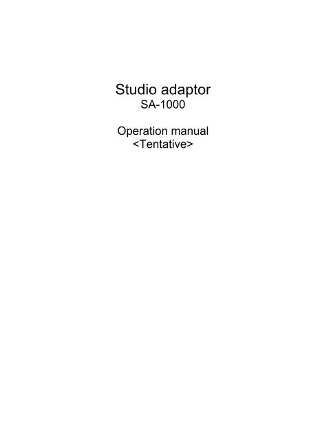
<strong>Studio</strong> <strong>adaptor</strong><br />
SA-1000<br />
Operation manual<br />
Rear panel of the SA-1000 operation<br />
CA-HF1000<br />
RET1/2 SEL switch<br />
Extender LED<br />
Light when lens<br />
Extender x0.8 is on<br />
POWER Lamp<br />
Light when camera<br />
Head power is supplied<br />
Viewfinder video<br />
select switches<br />
select R,G,B<br />
Return Select switch<br />
RET1,2<br />
Front tally switch<br />
Selects high/low/off<br />
Lens Extender switch<br />
Light when Extender<br />
is on<br />
Camera menu switch<br />
Call button<br />
Viewfinder display panel<br />
CS1/2<br />
Lights when ING is on.<br />
Memory switch<br />
CROSS,BOX1,BOX2 is memory<br />
Lights when ING is on.<br />
ND/CC select switch<br />
CROSS,BOX1,BOX2 switch<br />
CROSS,BOX1,BOX2 control<br />
Level volume<br />
Graticule of display level control<br />
Position H,V volume<br />
Adjustment of position<br />
Size H,V volume<br />
Adjustment of size
Video switches for the View Finder (R/G/B) operation<br />
R/G/B view finder video can be selected by R,G and B switches in the rear panel.<br />
The selected switch’<br />
s LED light and display video in the view finder.<br />
Return signal selection switch operation<br />
Return video signal can be selected by the Return Box, the rear panel of the Buildup Adapter and the lens<br />
return switch.<br />
<br />
From the Rear panel of the buildup Adapter<br />
Return signal<br />
<br />
<br />
<br />
<br />
Operational description<br />
CA-HF1000 RET1 The RET SEL switch is set to CH1 and the RET1 switch<br />
of Buildup adapter is pushed.<br />
CA-HF1000 RET2 The RET SEL switch is set to CH1 and the RET2 switch<br />
of Buildup adapter is pushed.<br />
CA-HF1000 RET1 The RET SEL switch is set to CH2 and the RET1 switch<br />
of Buildup adapter is pushed.<br />
CA-HF1000 RET2 The RET SEL switch is set to CH2 and the RET2 switch<br />
of Buildup adapter is pushed.<br />
CA-HF1000 RET1 The RET SEL switch is set to CH3 and the RET1 switch<br />
of Buildup adapter is pushed.<br />
CA-HF1000 RET2 The RET SEL switch is set to CH3 and the RET2 switch<br />
of Buildup adapter is pushed.<br />
CA-HF1000 RET1 The RET SEL switch is set to CH4 and the RET1 switch<br />
of Buildup adapter is pushed.<br />
CA-HF1000 RET2 The RET SEL switch is set to CH4 and the RET2 switch<br />
of Buildup adapter is pushed.<br />
<strong>Electric</strong> Filter operation<br />
The camera head has ND and CC filters. The selected switch’ s LED light. The ND and CC filter in the rear<br />
panel of the Buildup Adapter normally does not work unless given control from the RCU or SCU<br />
(CTLHEAD or FILTER HEAD).<br />
HD CAMERA SK-HD1000 <br />
ND Filer position<br />
CAP <br />
Filter display CAP CLEAR CROSS 1/16ND 1/64ND<br />
CC Filer position<br />
<br />
Filter display 3200K 4300K 5600K 6300K 8000K
EXTENDER SWITCH OPERATION<br />
THE X2 extender can be changed with the EXTENDER selection switch in the rear panel of the buildup<br />
Adapter. (This Extender switch can not control the x2 extender for the portable lens.)<br />
The LED light when the x2 extender “ ON” .<br />
<br />
FRONT TALLY SEL OPERATION<br />
This has three modes.<br />
H : High mode for Red Tally<br />
L : Low mode for Red Tally<br />
OFF : No red Tally<br />
(Optional tally in the studio type lens has only ON or OFF mode. The tally light at H & L mode.)<br />
FUNC/UP/DOWN/RIGHT/LEFT SWITCH OPERATION<br />
Press the FUNC switch then menu display in the viewfinder. Function in the menu can be selected with the<br />
UP/DOWN/RIGH/LEFT switch.<br />
* The camera head menu in addition to the viewfinder menu can be opened when CTL HEAD and it is<br />
self-controlled.<br />
CALL operation<br />
Press the CALL switch, the HEAD, VF, CCU, RU and the SU RED TALLY LED turn on.
SA CS-1/CS-2 display switch operation<br />
Press the CS-1/CS-2 switch and VF marker1/2, Focus IND can be changed.<br />
Also VF maker level can be adjusted NEGA toPOSI by the LEVEL variable register (VR). The CS-1/CS-2<br />
LED lights when the CS-1/CS-2 is ON.<br />
SA CS-1/2 Select<br />
TOP MENU<br />
VF :<br />
■ CUSTOM SW :<br />
CUSTOM SW MENU<br />
CS-1 SW<br />
: ZEBRA<br />
CA-CS SW : ---------<br />
LENS VTR SW : TALK<br />
SA CS-1 SW : MARKER1<br />
SA CS-2 SW : MARKER2<br />
MARKER1<br />
MARKER2<br />
FOCUS IND Select<br />
MARKER 1/2 Select<br />
TOP MENU<br />
VF :<br />
CUSTOM SW :<br />
VF MENU<br />
VF OUT SEL : COLOR<br />
VF DETAIL :<br />
VF MARKER :<br />
SIDE PANEL :<br />
VF DISPLAY :<br />
VF ZEBRA :<br />
VF MARKER<br />
USER SEL : USER 1<br />
MARKER1 SEL : <br />
MARKER2 SEL :<br />
OTHER SET :<br />
MARKER1 SEL<br />
CENTER MARK : ON<br />
SAFETY MARK : ON <br />
SIDE 4:3 : OFF<br />
13:9 : OFF<br />
14:9 : OFF<br />
15:9 : OFF<br />
<br />
FOCUS IND <br />
Press the FOCUS IND and the LED light and display 0 to 100 character in the top right of the VF.<br />
CROSS/BOX1/BOXn 2/MEMORY switch operatio<br />
Press the Cross, BOX1 or BOX2 individual switches, then previous position & size memory data are<br />
displayed in the view finder. Selected switch LED lights and display level can be adjusted by the LEVEL VR.<br />
Individual POSI and SIZE for H/V can be adjusted by the rotary ENC. Adjustable display is last selected<br />
data in the CROSS, BOX1 or BOX2. And also adjusted data can be stored to the memory by pressing the<br />
Memory switch. The Memory switch LED blinking lights during storing data.
LED INDICATERPOWER<br />
LED<br />
The Power LED lights when the camera head power is supplied.<br />
x0.8 LED<br />
The 0.8 LED lights when the lens extender in.
STUDIO ADAPTER SA-1000<br />
(Box type lens mount)<br />
CAMERA ATTACHMENT<br />
<br />
<br />
<br />
<br />
<br />
<br />
<br />
<br />
Move the lever to the Lock position<br />
and place the camera on the mount base.<br />
<br />
Move the lever to rock the mount base . Move each of the levers and to Adjust and fit of the camera in the bayonet<br />
the Unlock position.<br />
mount with holding the rear side of the<br />
camera, and then press down the lock lever.<br />
While pushing the slide release pin ,<br />
Camera attachment completed<br />
slide the camera into the bayonet mount.<br />
<br />
<br />
Place the levers and in the Lock<br />
position to stop the vertical and horizontal<br />
movements of the camera, respectively.<br />
Connect the viewfinder to camera.
STUDIO ADAPTER SA-1000<br />
(Box type lens mount)<br />
CAMERA REMOVAL<br />
<br />
<br />
<br />
<br />
<br />
Remove the view finder from the camera.<br />
Push the bayonet mount lever upward<br />
to unlock the camera.<br />
Pull the camera rearward to remove it<br />
from the bayonet mount.<br />
Pushing the release button .<br />
Move the lever to unlock the mount base.<br />
<br />
Camera removal completed<br />
Remove the camera from the mount base.
STUDIO ADAPTER SA-1000<br />
(Box type lens mount)<br />
Lens Mounting Plate Attachment<br />
<br />
Attachment completed<br />
<br />
<br />
<br />
<br />
Align the lugs of the build-up adapter with the lugs of the handy plate.<br />
Push the lower part of the handy plate.<br />
Secure the plate by locking the rock screw.<br />
M5 Hexagon wrench<br />
STUDIO ADAPTER SA-1000<br />
(Box type lens mount)<br />
Lens Mounting Plate Removal<br />
<br />
Removal completed<br />
<br />
<br />
Remove the camera lens, and then move<br />
the camera body rearward.<br />
Remove the camera from the mount base. Loose the rock screw. Lightly tap the upper part of the mounting.<br />
plate to disconnect the connector at the<br />
ower part. Then, remove the mounting plate.
STUDIO ADAPTER SA-1000<br />
(Box type lens mount)<br />
CAMERA ATTACHMENT<br />
<br />
<br />
<br />
<br />
<br />
<br />
<br />
<br />
Move the lever to the Lock position<br />
and place the camera on the mount base.<br />
<br />
Move the lever to rock the mount base . Move each of the levers and to Adjust and fit of the camera in the bayonet<br />
the Unlock position.<br />
mount with holding the rear side of the<br />
camera, and then press down the lock lever.<br />
While pushing the slide release pin ,<br />
Camera attachment completed<br />
slide the camera into the bayonet mount.<br />
<br />
<br />
Place the levers and in the Lock<br />
position to stop the vertical and horizontal<br />
movements of the camera, respectively.<br />
Connect the viewfinder to camera.
STUDIO ADAPTER SA-1000<br />
(Box type lens mount)<br />
CAMERA REMOVAL<br />
<br />
<br />
<br />
<br />
<br />
Remove the view finder from the camera.<br />
Push the bayonet mount lever upward<br />
to unlock the camera.<br />
Pull the camera rearward to remove it<br />
from the bayonet mount.<br />
Pushing the release button .<br />
Move the lever to unlock the mount base.<br />
<br />
Camera removal completed<br />
Remove the camera from the mount base.
STUDIO ADAPTER SA-1000<br />
(Box type lens mount)<br />
Lens Mounting Plate Attachment<br />
<br />
Attachment completed<br />
<br />
<br />
<br />
<br />
Align the lugs of the build-up adapter with the lugs of the handy plate.<br />
Push the lower part of the handy plate.<br />
Secure the plate by locking the rock screw.<br />
M5 Hexagon wrench<br />
STUDIO ADAPTER SA-1000<br />
(Box type lens mount)<br />
Lens Mounting Plate Removal<br />
<br />
Removal completed<br />
<br />
<br />
Remove the camera lens, and then move<br />
the camera body rearward.<br />
Remove the camera from the mount base. Loose the rock screw. Lightly tap the upper part of the mounting.<br />
plate to disconnect the connector at the<br />
ower part. Then, remove the mounting plate.