Generating High Direct Voltages Required voltage levels
Generating High Direct Voltages Required voltage levels
Generating High Direct Voltages Required voltage levels
- No tags were found...

You also want an ePaper? Increase the reach of your titles
YUMPU automatically turns print PDFs into web optimized ePapers that Google loves.
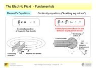
<strong>Generating</strong> <strong>High</strong> <strong>Direct</strong> <strong>Voltages</strong><br />
<strong>Required</strong> <strong>voltage</strong> <strong>levels</strong><br />
Industrial facilities and components (dust filters, epoxy resin powder coating<br />
systems): up to about 100 kV<br />
Medicine technology, diagnostics (x-ray units): several 100 kV<br />
HVDC: up to 800 kV (China; planned: 1000 kV)<br />
<strong>High</strong>-<strong>voltage</strong> test laboratories: up to ca. 3 MV<br />
Physical research (e.g. particle accelerators): up to ca. 25 MV<br />
Fachgebiet<br />
Hochspannungstechnik<br />
<strong>High</strong>-Voltage Engineering / Chapter 3 - 1 -
<strong>Generating</strong> <strong>High</strong> <strong>Direct</strong> <strong>Voltages</strong><br />
<strong>Required</strong> <strong>voltage</strong> <strong>levels</strong><br />
Specification for insulation coordination<br />
of HVDV converter stations<br />
recently published<br />
IEC Technical Specification<br />
IEC TS 60071-5: Insulation Co-ordination<br />
Part 5: Procedures for high-<strong>voltage</strong><br />
direct current (HVDC) Converter Stations"<br />
... but no standard insulation <strong>levels</strong> given!<br />
Fachgebiet<br />
Hochspannungstechnik<br />
<strong>High</strong>-Voltage Engineering / Chapter 3 - 2 -
<strong>Generating</strong> <strong>High</strong> <strong>Direct</strong> <strong>Voltages</strong><br />
Definitions and requirements<br />
according to IEC 60060-1<br />
Fachgebiet<br />
Hochspannungstechnik<br />
<strong>High</strong>-Voltage Engineering / Chapter 3 - 3 -
<strong>Generating</strong> <strong>High</strong> <strong>Direct</strong> <strong>Voltages</strong><br />
Definitions (according to IEC 60060-1)<br />
Amplitude of a direct <strong>voltage</strong> = arithmetic mean value:<br />
T<br />
1<br />
U= ∫ut ( )dt<br />
T<br />
"Ripple":<br />
0<br />
1<br />
δ U = ( û−<br />
umin<br />
)<br />
2<br />
"Ripple factor":<br />
δU<br />
U<br />
2δU<br />
u<br />
+ + +<br />
- - -<br />
û<br />
U<br />
u min<br />
t<br />
Fachgebiet<br />
Hochspannungstechnik<br />
<strong>High</strong>-Voltage Engineering / Chapter 3 - 4 -
<strong>Generating</strong> <strong>High</strong> <strong>Direct</strong> <strong>Voltages</strong><br />
Requirements (according to IEC 60060-1)<br />
Ripple factor ≤ 3%<br />
(Note: Therefore measurement of rms value will also give exact results)<br />
At test durations ≤ 60 s: change in amplitude max. ± 1%<br />
(Note: not to be mixed up with measuring uncertainty!)<br />
At test duration > 60 s: change in amplitude max. ± 3%<br />
Charging of the test circuit in "reasonably short time"<br />
(Note 1: charging times of several minutes possible!<br />
Note 2: for dc bushings steady-state conditions after several hours!)<br />
Polarity reversal (if required) in short time<br />
Fachgebiet<br />
Hochspannungstechnik<br />
<strong>High</strong>-Voltage Engineering / Chapter 3 - 5 -
<strong>Generating</strong> <strong>High</strong> <strong>Direct</strong> <strong>Voltages</strong><br />
Ways of generating direct <strong>voltage</strong>s<br />
By rectifying alternating <strong>voltage</strong><br />
By charge separation<br />
Single phase<br />
Two-phase<br />
Band generators<br />
(after Van de Graaff)<br />
• One-way rectifier (w – w/o smoothing)<br />
• Rectifier bridges (w – w/o smoothing)<br />
• Doubling circuits (w – w/o smoothing)<br />
• Multiplier circuits<br />
Three-phase<br />
6-pulse-bridges<br />
12-pulse-bridges<br />
Fachgebiet<br />
Hochspannungstechnik<br />
<strong>High</strong>-Voltage Engineering / Chapter 3 - 6 -
<strong>Generating</strong> <strong>High</strong> <strong>Direct</strong> <strong>Voltages</strong> by help of Rectifiers<br />
Vacuum valve<br />
„Ideal“ valve<br />
Reverse <strong>voltage</strong> up to 100 kV<br />
Complex (heating!)<br />
Only in old (still existing) equipment<br />
Fachgebiet<br />
Hochspannungstechnik<br />
<strong>High</strong>-Voltage Engineering / Chapter 3 - 7 -
<strong>Generating</strong> <strong>High</strong> <strong>Direct</strong> <strong>Voltages</strong> by help of Rectifiers<br />
Semi-conductor rectifier<br />
Selenium (Se)<br />
Germanium (Ge)<br />
Silicon (Si)<br />
Se-Rectifier<br />
Fachgebiet<br />
Hochspannungstechnik<br />
<strong>High</strong>-Voltage Engineering / Chapter 3 - 8 -
<strong>Generating</strong> <strong>High</strong> <strong>Direct</strong> <strong>Voltages</strong> by help of Rectifiers<br />
Semi-conductor rectifier<br />
Se Ge Si<br />
max. reverse <strong>voltage</strong> (V) 50 300 2000<br />
max. current density (A/cm 2 ) 0,5 150 150<br />
junction capacitance several nF few pF<br />
reverse resistance kΩ range MΩ range<br />
variance of reverse resistance 1:5 1:1000<br />
Fachgebiet<br />
Hochspannungstechnik<br />
<strong>High</strong>-Voltage Engineering / Chapter 3 - 9 -
<strong>Generating</strong> <strong>High</strong> <strong>Direct</strong> <strong>Voltages</strong> by help of Rectifiers<br />
Semi-conductor rectifier<br />
Today virtually always applied: Si rectifiers<br />
Problem with the small junction capacitance and the large<br />
variance of the reverse resistance ........<br />
RC network required:<br />
Fachgebiet<br />
Hochspannungstechnik<br />
<strong>High</strong>-Voltage Engineering / Chapter 3 - 10 -
<strong>Generating</strong> <strong>High</strong> <strong>Direct</strong> <strong>Voltages</strong> by help of Rectifiers<br />
Semi-conductor rectifier<br />
Implementation example: rectifier of 3.4 MV<br />
maximum reverse <strong>voltage</strong> (TU Munich)<br />
Fachgebiet<br />
Hochspannungstechnik<br />
<strong>High</strong>-Voltage Engineering / Chapter 3 - 11 -
<strong>Generating</strong> <strong>High</strong> <strong>Direct</strong> <strong>Voltages</strong> by help of Rectifiers<br />
One-way rectifier circuit<br />
Peak value: û = û T<br />
Arithmetic<br />
mean value:<br />
U<br />
1<br />
= û<br />
π<br />
Maximum<br />
reverse <strong>voltage</strong>: û V = û T<br />
Fachgebiet<br />
Hochspannungstechnik<br />
<strong>High</strong>-Voltage Engineering / Chapter 3 - 12 -
<strong>Generating</strong> <strong>High</strong> <strong>Direct</strong> <strong>Voltages</strong> by help of Rectifiers<br />
One-way rectifier circuit with smoothing capacitor<br />
Peak value: û = û T<br />
Arithmetic<br />
mean value:<br />
U ≈û−δU<br />
Maximum<br />
reverse <strong>voltage</strong>: û V = 2û T<br />
Fachgebiet<br />
Hochspannungstechnik<br />
<strong>High</strong>-Voltage Engineering / Chapter 3 - 13 -
<strong>Generating</strong> <strong>High</strong> <strong>Direct</strong> <strong>Voltages</strong> by help of Rectifiers<br />
One-way rectifier circuit with smoothing capacitor<br />
Calculation of ripple:<br />
Due to:<br />
V t « T and δU « U<br />
assumption of a linear capacitor discharge (instead of exponential)<br />
Then: change of charge<br />
T<br />
2δU ⋅ C = ∫ igdt ≈T ⋅I<br />
δU<br />
≈<br />
I<br />
g<br />
0<br />
1<br />
2 fC<br />
g<br />
Fachgebiet<br />
Hochspannungstechnik<br />
<strong>High</strong>-Voltage Engineering / Chapter 3 - 14 -
<strong>Generating</strong> <strong>High</strong> <strong>Direct</strong> <strong>Voltages</strong> by help of Rectifiers<br />
One-way rectifier circuit with smoothing capacitor<br />
δU<br />
≈<br />
I<br />
g<br />
1<br />
2 fC<br />
In order to reduce the ripple at given load current:<br />
• increase C<br />
• increase f<br />
--> usual: f up to several kHz<br />
+<br />
~<br />
Improvement also possible by two-way rectification:<br />
-<br />
Fachgebiet<br />
Hochspannungstechnik<br />
<strong>High</strong>-Voltage Engineering / Chapter 3 - 15 -
<strong>Generating</strong> <strong>High</strong> <strong>Direct</strong> <strong>Voltages</strong> by help of Rectifiers<br />
One-way rectifier circuit with/without smoothing capacitor<br />
Load curve<br />
U i0 ... imaginary open circuit <strong>voltage</strong><br />
n ... number of rectifiers<br />
U 1 ... conducting-state <strong>voltage</strong> of<br />
one individual rectifier<br />
( ) g<br />
U= U −nU ⋅ −k⋅I<br />
i0 1<br />
„k“ generator specific<br />
Fachgebiet<br />
Hochspannungstechnik<br />
<strong>High</strong>-Voltage Engineering / Chapter 3 - 16 -
Multiplier Circuits<br />
Villard-Circuit<br />
• Booster capacitor charged to û T<br />
• Potential of high-<strong>voltage</strong> terminal increased to:<br />
u(t) = u T + U c<br />
Peak value: û = 2û T<br />
Arithmetic<br />
mean value:<br />
U<br />
= û<br />
T<br />
Maximum<br />
reverse <strong>voltage</strong>: û V ≈ 2û T<br />
Fachgebiet<br />
Hochspannungstechnik<br />
<strong>High</strong>-Voltage Engineering / Chapter 3 - 17 -
Multiplier Circuits<br />
Villard-Circuit<br />
Smoothing of the <strong>voltage</strong> not possible with the Villard-circuit!<br />
Fachgebiet<br />
Hochspannungstechnik<br />
<strong>High</strong>-Voltage Engineering / Chapter 3 - 18 -
Multiplier Circuits<br />
Greinacher doubling circuit<br />
Villard-Circuit<br />
Connection of a smoothing<br />
capacitor via a second<br />
rectifier diode!<br />
Fachgebiet<br />
Hochspannungstechnik<br />
<strong>High</strong>-Voltage Engineering / Chapter 3 - 19 -
Multiplier Circuits<br />
Greinacher doubling circuit<br />
u V1 = u T + U C1 mit û V1 = 2û T<br />
⇒ Charging of C 2 to û V1 = 2û T<br />
Peak value: û = 2û T<br />
Arithmetic<br />
mean value:<br />
U<br />
=<br />
2û<br />
T<br />
Maximum<br />
reverse <strong>voltage</strong>:<br />
û V1 = û V2 ≈ 2û T<br />
Fachgebiet<br />
Hochspannungstechnik<br />
<strong>High</strong>-Voltage Engineering / Chapter 3 - 20 -
Multiplier Circuits<br />
Greinacher-Cascade<br />
(Cockroft/Walton Multiplier)<br />
(Greinacher 1920, Cockroft/Walton 1932)<br />
Fachgebiet<br />
Hochspannungstechnik<br />
<strong>High</strong>-Voltage Engineering / Chapter 3 - 21 -
Multiplier Circuits<br />
Greinacher-Cascade: open circuit <strong>voltage</strong>s<br />
Fachgebiet<br />
Hochspannungstechnik<br />
<strong>High</strong>-Voltage Engineering / Chapter 3 - 22 -
Multiplier Circuits<br />
Greinacher-Cascade: open circuit <strong>voltage</strong>s<br />
Fachgebiet<br />
Hochspannungstechnik<br />
<strong>High</strong>-Voltage Engineering / Chapter 3 - 23 -
Multiplier Circuits<br />
Greinacher-Cascade: open circuit <strong>voltage</strong>s<br />
Fachgebiet<br />
Hochspannungstechnik<br />
<strong>High</strong>-Voltage Engineering / Chapter 3 - 24 -
Multiplier Circuits<br />
Greinacher-Cascade: open circuit <strong>voltage</strong>s<br />
Fachgebiet<br />
Hochspannungstechnik<br />
<strong>High</strong>-Voltage Engineering / Chapter 3 - 25 -
Multiplier Circuits<br />
Greinacher-Cascade: open circuit <strong>voltage</strong>s<br />
Fachgebiet<br />
Hochspannungstechnik<br />
<strong>High</strong>-Voltage Engineering / Chapter 3 - 26 -
Multiplier Circuits<br />
Greinacher-Cascade: open circuit <strong>voltage</strong>s<br />
Fachgebiet<br />
Hochspannungstechnik<br />
<strong>High</strong>-Voltage Engineering / Chapter 3 - 27 -
Multiplier Circuits<br />
Greinacher-Cascade: open circuit <strong>voltage</strong>s<br />
Fachgebiet<br />
Hochspannungstechnik<br />
<strong>High</strong>-Voltage Engineering / Chapter 3 - 28 -
Multiplier Circuits<br />
Greinacher-Cascade: open circuit <strong>voltage</strong>s<br />
Fachgebiet<br />
Hochspannungstechnik<br />
<strong>High</strong>-Voltage Engineering / Chapter 3 - 29 -
Multiplier Circuits<br />
Greinacher-Cascade<br />
Booster column<br />
Smoothing column<br />
C 1 = C 2 = C 0 /2<br />
⇒ All capacitors carry the<br />
same charge!<br />
(Q = C·U)<br />
Fachgebiet<br />
Hochspannungstechnik<br />
<strong>High</strong>-Voltage Engineering / Chapter 3 - 30 -
Multiplier Circuits<br />
Greinacher-Cascade: <strong>voltage</strong>s in load condition<br />
Imaginary direct <strong>voltage</strong> n·2û T<br />
decreased by <strong>voltage</strong> drop ΔU<br />
Charge of:<br />
Ripple <strong>voltage</strong> 2δU has a<br />
different shape than ripple<br />
<strong>voltage</strong> in the doubling circuit<br />
Fachgebiet<br />
Hochspannungstechnik<br />
<strong>High</strong>-Voltage Engineering / Chapter 3 - 31 -
Multiplier Circuits<br />
Greinacher-Cascade: <strong>voltage</strong>s in load condition<br />
Voltage drop:<br />
Ripple:<br />
3 2<br />
Ig 8n 3n n<br />
+ +<br />
∆ U = ⋅ f ⋅ C 12<br />
( )<br />
g n n 1<br />
I +<br />
δ U = ⋅ f ⋅ C 4<br />
⇒ Depends on number of stages, load current, frequency and capacitance,<br />
but not on amplitude of the direct <strong>voltage</strong>!<br />
Fachgebiet<br />
Hochspannungstechnik<br />
<strong>High</strong>-Voltage Engineering / Chapter 3 - 32 -
Multiplier Circuits<br />
Greinacher-Cascade: <strong>voltage</strong>s in load condition<br />
3 2<br />
Ig 8n 3n n<br />
+ +<br />
∆ U = ⋅ f ⋅ C 12<br />
( )<br />
g n n 1<br />
I +<br />
δ U = ⋅ f ⋅ C 4<br />
Greinacher-cascades should always be operated as close as<br />
possible to their upper <strong>voltage</strong> limits.<br />
If lower <strong>voltage</strong>s are requested part of the stages should preferably<br />
be shorted in order to operate the remaining stages at their upper<br />
<strong>voltage</strong> limits.<br />
Optimum stage <strong>voltage</strong> = 400 kV for cascades of 1 MV ... 2 MV<br />
Fachgebiet<br />
Hochspannungstechnik<br />
<strong>High</strong>-Voltage Engineering / Chapter 3 - 33 -
Multiplier Circuits<br />
Greinacher-Cascade: <strong>voltage</strong>s in load condition<br />
(C = 60 nF, f = 50 Hz, I g = 10 mA)<br />
600<br />
40<br />
Voltage drop / kV<br />
500<br />
400<br />
300<br />
200<br />
100<br />
Parameter:<br />
I = 10 mA, C = 60 nF, f = 50 Hz<br />
Ripple / kV<br />
35<br />
30<br />
25<br />
20<br />
15<br />
10<br />
5<br />
Parameter:<br />
I = 10 mA, C = 60 nF, f = 50 Hz<br />
0<br />
1 2 3 4 5 6<br />
0<br />
1 2 3 4 5 6<br />
Stage no. n<br />
Stage no. n<br />
n = 4:<br />
Voltage drop ΔU = 157 kV<br />
Ripple δU = 17 kV<br />
Requirement of IEC 60060-1: δU ≤ 3% only fulfilled for <strong>voltage</strong>s ≥ 567 kV!<br />
Fachgebiet<br />
Hochspannungstechnik<br />
<strong>High</strong>-Voltage Engineering / Chapter 3 - 34 -
Multiplier Circuits<br />
Greinacher-Cascade: two-phase circuit<br />
Booster columns<br />
Smoothing column<br />
Considerable improvement<br />
of <strong>voltage</strong> drop and ripple<br />
Consequential further step:<br />
three-phase circuit<br />
Fachgebiet<br />
Hochspannungstechnik<br />
<strong>High</strong>-Voltage Engineering / Chapter 3 - 35 -
Multiplier Circuits<br />
Greinacher-Cascade: two-phase circuit<br />
Protection of top stage<br />
and of transformer<br />
by spark gaps or<br />
surge arresters<br />
Protection of the whole<br />
cascade by a damping<br />
resistor<br />
Fachgebiet<br />
Hochspannungstechnik<br />
<strong>High</strong>-Voltage Engineering / Chapter 3 - 36 -
Multiplier Circuits<br />
Transformer supported cascades<br />
Currents > 100 mA at low <strong>voltage</strong><br />
drop and ripple possible<br />
Transformer must be dc resistant<br />
Cascading of the transformers by<br />
excitation and coupling windings<br />
or<br />
Simple transformers, fed by<br />
insulated generators<br />
Fachgebiet<br />
Hochspannungstechnik<br />
<strong>High</strong>-Voltage Engineering / Chapter 3 - 37 -
Multiplier Circuits<br />
Greinacher-Cascades: Physical arrangement<br />
Fachgebiet<br />
Hochspannungstechnik<br />
<strong>High</strong>-Voltage Engineering / Chapter 3 - 38 -
Multiplier Circuits<br />
Greinacher-Cascades: Physical arrangement<br />
Fachgebiet<br />
Hochspannungstechnik<br />
<strong>High</strong>-Voltage Engineering / Chapter 3 - 39 -
Multiplier Circuits - Implementation Examples<br />
<strong>Direct</strong> <strong>voltage</strong> add-on 600 kV/15 mA<br />
built by TuR for University of Damaskus<br />
- 2 stages<br />
- Air cushion base<br />
Fachgebiet<br />
Hochspannungstechnik<br />
<strong>High</strong>-Voltage Engineering / Chapter 3 - 40 -
Multiplier Circuits - Implementation Examples<br />
(Note: circuit diagram<br />
shows 2 stages only.)<br />
<strong>Direct</strong> <strong>voltage</strong> generator 900 kV/40 mA<br />
built by TuR for Cable Works Budapest<br />
- 3 stages<br />
- Automatic change of polarity<br />
Fachgebiet<br />
Hochspannungstechnik<br />
<strong>High</strong>-Voltage Engineering / Chapter 3 - 41 -
Multiplier Circuits - Implementation Examples<br />
Greinacher-Cascade<br />
2 MV (TU Berlin)<br />
Fachgebiet<br />
Hochspannungstechnik<br />
<strong>High</strong>-Voltage Engineering / Chapter 3 - 42 -
Multiplier Circuits - Implementation Examples<br />
Greinacher-Cascade<br />
2 MV (TU Berlin)<br />
... here during a test on an 800-kV-<br />
DC <strong>voltage</strong> divider<br />
(Source: Omicron, Trench)<br />
Fachgebiet<br />
Hochspannungstechnik<br />
<strong>High</strong>-Voltage Engineering / Chapter 3 - 43 -
Multiplier Circuits - Implementation Examples<br />
Greinacher-Cascade<br />
(CESI, Milan/Italy)<br />
Fachgebiet<br />
Hochspannungstechnik<br />
<strong>High</strong>-Voltage Engineering / Chapter 3 - 44 -
Multiplier Circuits - Implementation Examples<br />
Greinacher-Cascade<br />
(<strong>High</strong>Volt, for ABB Ludvika)<br />
Fachgebiet<br />
Hochspannungstechnik<br />
<strong>High</strong>-Voltage Engineering / Chapter 3 - 45 -
Multiplier Circuits - Implementation Examples<br />
Greinacher-Cascade<br />
(CESI, Milan/Italy)<br />
cable testing<br />
Fachgebiet<br />
Hochspannungstechnik<br />
<strong>High</strong>-Voltage Engineering / Chapter 3 - 46 -
Multiplier Circuits - Implementation Examples<br />
Two-phase (symmetrical)<br />
seven stage<br />
Greinacher-cascade 3.4 MV<br />
(Circuit diagram: two-phase (symmetrical) four stage Greinacher-cascade)<br />
Fachgebiet<br />
Hochspannungstechnik<br />
<strong>High</strong>-Voltage Engineering / Chapter 3 - 47 -
Multiplier Circuits - Implementation Examples<br />
<strong>Direct</strong> <strong>voltage</strong> generator 1600 kV/200 mA<br />
(built by TuR)<br />
- 4 stages<br />
- 500 Hz supply<br />
- Si-rectifiers<br />
- Four 450-kV rectifiers each combined in a rhombic frame<br />
- Frames to be pivoted by motor drives for change of polarity<br />
Fachgebiet<br />
Hochspannungstechnik<br />
<strong>High</strong>-Voltage Engineering / Chapter 3 - 48 -
Multiplier Circuits - Implementation Examples<br />
<strong>Direct</strong> <strong>voltage</strong> generator 2000 kV/10 mA<br />
(built by TuR for Toshiba/Japan)<br />
- 7 stages<br />
- Fed by two transformers on 2/7- and 6/7-potential<br />
- Seismic resistant design<br />
- Air cushion base for high mobility<br />
- Change of polarity under load within 200 ms (up to 750 kV)<br />
Fachgebiet<br />
Hochspannungstechnik<br />
<strong>High</strong>-Voltage Engineering / Chapter 3 - 49 -
Multiplier Circuits - Implementation Examples<br />
Booster columns<br />
Smoothing<br />
column<br />
Pulsating <strong>voltage</strong> test generator 1600 kV (circuit diagram)<br />
3 stage direct <strong>voltage</strong> generator,<br />
3-phase double way rectifier type<br />
3-phase double-way bridge<br />
Feeding transformer<br />
500-kV transformer; series connected to the direct <strong>voltage</strong> generator<br />
Insulating transformer<br />
Fachgebiet<br />
Hochspannungstechnik<br />
<strong>High</strong>-Voltage Engineering / Chapter 3 - 50 -
Multiplier Circuits - Implementation Examples<br />
Pulsating <strong>voltage</strong><br />
test generator 1600 kV;<br />
erection in the test lab<br />
for commissioning test<br />
Fachgebiet<br />
Hochspannungstechnik<br />
<strong>High</strong>-Voltage Engineering / Chapter 3 - 51 -
Multiplier Circuits - Implementation Examples<br />
Greinacher-Cascade 16 kV<br />
(built from electronic components)<br />
Fachgebiet<br />
Hochspannungstechnik<br />
<strong>High</strong>-Voltage Engineering / Chapter 3 - 52 -