History of Raman Technology Development - Academic Program ...
History of Raman Technology Development - Academic Program ...
History of Raman Technology Development - Academic Program ...

You also want an ePaper? Increase the reach of your titles
YUMPU automatically turns print PDFs into web optimized ePapers that Google loves.
Waters Symposium: <strong>Raman</strong> Spectroscopy<br />
density. The bright spots are diffraction orders. Between and<br />
around the diffraction spots from the conventionally ruled<br />
grating is a significant quantity <strong>of</strong> light due to imperfections<br />
in the grating. The improvement in performance <strong>of</strong> holographic<br />
gratings has the potential for much improved stray<br />
light rejection in <strong>Raman</strong> spectrometers and spectrographs.<br />
Figure 11 shows the optical layout <strong>of</strong> the HG2S, the first<br />
<strong>Raman</strong> spectrometer based on holographically recorded gratings.<br />
This instrument was introduced in 1971. It was neither<br />
a Czerny–Turner nor a Sergent-Rozey. It used concave<br />
gratings. It was not necessary to have any optics other than<br />
the gratings between the slits. Consequently there were no<br />
additional sources <strong>of</strong> stray light. The low frequency performance<br />
<strong>of</strong> this instrument was significantly improved over<br />
anything that preceded it. Spectra could be recorded to frequency<br />
shifts lower than 10 cm 1 . Figure 12 shows the very<br />
low frequency spectrum <strong>of</strong> SiO 2 .<br />
Before the use <strong>of</strong> computers, spectra were scanned synchronously<br />
with strip chart recorders. Most spectrometers<br />
have drive systems where linear movement <strong>of</strong> a stepper motor<br />
is related to the wavelength diffracted by the grating.<br />
However, the <strong>Raman</strong> spectrum is described naturally in terms<br />
<strong>of</strong> shifts in the reciprocal <strong>of</strong> the wavelengths. That meant that<br />
a different drive system evolved for <strong>Raman</strong> instruments. The<br />
diffraction equation relating the incident and scattered angles<br />
i and i, to the wavelength <strong>of</strong> light is<br />
sini + sini′ = knλ<br />
where k is the diffraction order and n is the index <strong>of</strong> refraction<br />
(= 1 in air). Simple geometric arguments indicate how it<br />
is possible to devise a mechanical system that can scan in cm 1<br />
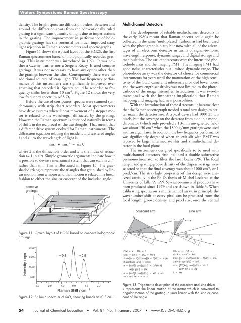
rather than nm. This is illustrated in Figure 13. The grayshaded<br />
triangles represent the triangles that get pushed by linear<br />
motion from a motor and that motion is related in a linear<br />
fashion to either the sine or cosecant <strong>of</strong> the included angle.<br />
Multichannel Detectors<br />
The development <strong>of</strong> reliable multichannel detectors in<br />
the early 1980s meant that <strong>Raman</strong> spectra could again be<br />
collected in the same “multiplexed” fashion as had been used<br />
with the photographic plate, but now with all <strong>of</strong> the advantages<br />
<strong>of</strong> an electronic detector in terms <strong>of</strong> signal-to-noise,<br />
wavelength response, dynamic range, and digital storage and<br />
manipulation. The earliest detectors were the intensified photodiode<br />
array and the imaging PMT. The imaging PMT had<br />
good noise characteristics but limited dynamic range. The<br />
photodiode array was the detector <strong>of</strong> choice for commercial<br />
instruments for years until the maturation <strong>of</strong> the high sensitivity<br />
<strong>of</strong> the CCD camera. It inherently provided lower noise,<br />
and the wavelength sensitivity was not limited to the photocathode<br />
<strong>of</strong> the image intensifier. In addition, it was two-dimensional<br />
with the important implication that <strong>Raman</strong><br />
mapping and imaging had new possibilities.<br />
With the introduction <strong>of</strong> these detectors, it became clear<br />
that the <strong>Raman</strong> spectrograph needed a total new design to better<br />
match the detector size. A typical device had 1000 25 µm<br />
pixels, but the coverage on the detector from a double monochromator<br />
(which only provided a 18-mm unvignetted field)<br />
was about 150 cm 1 when the 1800 gmm gratings were used<br />
with an argon laser. In addition, the low frequency performance<br />
was significantly degraded when an exit slit with PMT was<br />
replaced by larger intermediate slits and a multichannel detector<br />
in the focal plane.<br />
The instruments designed specifically to be used with<br />
multichannel detectors first included a double subtractive<br />
premonochromator to filter the laser beam (20). The focal<br />
length and grating groove density <strong>of</strong> the dispersive stage were<br />
selected so that the final coverage was about 1000 cm 1 , or 1<br />
pixelcm. The stray light properties <strong>of</strong> this design were analyzed<br />
carefully in the Ph.D. thesis <strong>of</strong> Michel Leclercq at the<br />
University <strong>of</strong> Lille (21, 22). Several commercial products have<br />
been produced since 1979 and are shown in Table 3. When<br />
calibrating spectra on a multichannel array, in principle the<br />
wavenumber shift at every pixel can be predicted from the<br />
focal length, groove density, and pixel size, once the central<br />
Figure 11. Optical layout <strong>of</strong> HG2S based on concave holographic<br />
gratings.<br />
Figure 12. Brillouin spectrum <strong>of</strong> SiO 2 showing bands at ±0.8 cm 1 .<br />
Figure 13. Trigometric description <strong>of</strong> the cosecant and sine drives—<br />
x represents the linear motion <strong>of</strong> the motor which is converted to<br />
angular motion <strong>of</strong> the grating in units linear with the sine or cosecant<br />
<strong>of</strong> the angle.<br />
54 Journal <strong>of</strong> Chemical Education • Vol. 84 No. 1 January 2007 • www.JCE.DivCHED.org