History of Raman Technology Development - Academic Program ...
History of Raman Technology Development - Academic Program ...
History of Raman Technology Development - Academic Program ...

You also want an ePaper? Increase the reach of your titles
YUMPU automatically turns print PDFs into web optimized ePapers that Google loves.
Waters Symposium: <strong>Raman</strong> Spectroscopy<br />
Figure 22. (Top) Optical principle describing how light is collected<br />
and imaged from the <strong>Raman</strong> volume to the spectrograph. (Bottom)<br />
Implementation <strong>of</strong> this principle. Note the pinhole spatial filter that<br />
will serve as a confocal hole for increased spatial resolution. These<br />
figures are reproduced from Figures 9 and 10 <strong>of</strong> ref 31.<br />
The principle <strong>of</strong> confocality is described in Figure 23.<br />
The idea is that insertion <strong>of</strong> an aperture in a plane conjugated<br />
to the plane <strong>of</strong> analysis will block <strong>Raman</strong> radiation<br />
emitted by material surrounding the laser-irradiated volume.<br />
This has the effect <strong>of</strong> assuring that the <strong>Raman</strong> spectrum represents<br />
the material <strong>of</strong> interest, as well as blocking fluorescence<br />
and Rayleigh light. The degree <strong>of</strong> confocality will be<br />
determined by the size <strong>of</strong> this hole relative to the size <strong>of</strong> the<br />
image, as well as the NA <strong>of</strong> the microscope optics.<br />
The early 1990s saw the development <strong>of</strong> a method to<br />
map samples confocally while multiplexing the laser beam<br />
on the sample and taking advantage <strong>of</strong> the second dimension<br />
<strong>of</strong> the CCD (32). The principle is shown in Figure 24.<br />
The laser is scanned across the back aperture <strong>of</strong> the objective<br />
in such a way as to avoid introducing aberrations and<br />
then losing the diffraction limit in the laser spot. The <strong>Raman</strong><br />
light returns on the same scanning mirror so that it<br />
can be then focused through the confocal hole and rescanned<br />
onto the entrance slit <strong>of</strong> the spectrograph. Each<br />
point on the slit represents <strong>Raman</strong> signal from a confocally<br />
defined spot on the sample. By appropriately processing the<br />
signal on the CCD, one can construct a <strong>Raman</strong> map that is<br />
truly confocal.<br />
While certainly <strong>Raman</strong> micrographs can be recorded directly<br />
as was shown earlier, the confocal mapping provides<br />
significant advantages to these capabilities. <strong>Raman</strong> signals tend<br />
to be weak and are easily overwhelmed by background signals.<br />
In the case <strong>of</strong> microscopy, this can be matrix signals (i.e.,<br />
from material around the directly illuminated spot) as well<br />
as luminescence and Rayleigh light. Confocal aperturing reduces<br />
most <strong>of</strong> these unwanted signals so that the resulting<br />
<strong>Raman</strong> images have much better contrast. While sometimes<br />
it is possible to subtract these background levels, subtraction<br />
will never remove the noise created by high background levels.<br />
Figure 25 shows the results <strong>of</strong> a confocal map <strong>of</strong> a histological<br />
section containing Dacron (polyethylene terephthalate)<br />
fibers with adhering protein. Note that this map was performed<br />
with a HeNe laser on a “real-world” sample.<br />
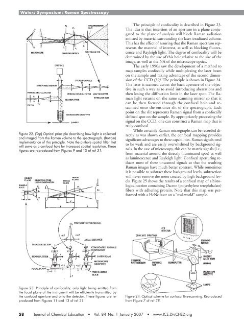
Figure 23. Principle <strong>of</strong> confocality: only light being emitted from<br />
the focal plane <strong>of</strong> the instrument will be efficiently transmitted by<br />
the confocal aperture and onto the detector. These figures are reproduced<br />
from Figures 11 and 13 <strong>of</strong> ref 31.<br />
Figure 24. Optical scheme for confocal line-scanning. Reproduced<br />
from Figure 7 <strong>of</strong> ref 38.<br />
58 Journal <strong>of</strong> Chemical Education • Vol. 84 No. 1 January 2007 • www.JCE.DivCHED.org