Debris Basin and Deflection Berm Design for Fire-Related Debris ...
Debris Basin and Deflection Berm Design for Fire-Related Debris ...
Debris Basin and Deflection Berm Design for Fire-Related Debris ...

You also want an ePaper? Increase the reach of your titles
YUMPU automatically turns print PDFs into web optimized ePapers that Google loves.
<strong>Debris</strong> <strong>Basin</strong> <strong>and</strong> <strong>Deflection</strong> <strong>Berm</strong> <strong>Design</strong> <strong>for</strong> <strong>Fire</strong>-<strong>Related</strong><br />
<strong>Debris</strong>-Flow Mitigation<br />
ADAM B. PROCHASKA 1<br />
PAUL M. SANTI<br />
JERRY D. HIGGINS<br />
Colorado School of Mines, Department of Geology <strong>and</strong> Geological Engineering,<br />
1516 Illinois Street, Golden, CO 80401<br />
Key Terms: <strong>Debris</strong> Flow, <strong>Fire</strong>-<strong>Related</strong>, Mitigation,<br />
<strong>Design</strong>, <strong>Basin</strong>, <strong>Deflection</strong> <strong>Berm</strong><br />
ABSTRACT<br />
<strong>Debris</strong> flows are hazardous because of their poor<br />
predictability, high impact <strong>for</strong>ces, <strong>and</strong> ability to deposit<br />
large quantities of sediment in inundated areas. To<br />
minimize the risk to developments on alluvial fans,<br />
debris-flow mitigation structures may be required. This<br />
study reviewed the state of practice <strong>for</strong> the design of<br />
two types of debris-flow mitigation structures: basins<br />
<strong>and</strong> deflection berms. Published guidelines <strong>for</strong> these<br />
structures are rare, <strong>and</strong> there appears to be little<br />
st<strong>and</strong>ardization. Recommended design improvements,<br />
particularly <strong>for</strong> fire-related debris flows, include<br />
incorporating several recent developments in debrisflow<br />
mitigation design, reducing subjectivity, <strong>and</strong><br />
enhancing the technical basis <strong>for</strong> the designs. Specific<br />
shortcomings of existing design methodologies include<br />
techniques <strong>for</strong> predicting debris-flow volume, specifications<br />
<strong>for</strong> berm geometry, impact loading considerations,<br />
<strong>and</strong> lack of flexibility in outlet works design, among<br />
others. Proposed solutions <strong>and</strong> guidelines <strong>for</strong> these<br />
issues are presented.<br />
INTRODUCTION<br />
1 Present Address: RJH Consultants, Inc., 9800 Mt. Pyramid Court,<br />
Suite 330, Englewood, CO 80112. Phone: 303-225-4611, Fax: 303-225-<br />
4615.<br />
With an ever increasing population, urban<br />
development will need to further encroach into<br />
geologically hazardous areas. One such example of<br />
a hazardous area is an alluvial fan, which may be<br />
susceptible to debris flows. VanDine (1985) defines a<br />
debris flow as being ‘‘a mass movement that involves<br />
water-charged, predominantly coarse-grained inorganic<br />
<strong>and</strong> organic material flowing rapidly down a<br />
steep, confined, preexisting channel.’’ <strong>Debris</strong> flows<br />
are hazardous because of their poor predictability,<br />
high impact <strong>for</strong>ces, <strong>and</strong> ability to deposit large<br />
quantities of sediment in inundated areas (Jakob<br />
<strong>and</strong> Hungr, 2005).<br />
<strong>Debris</strong>-flow hazards increase following a <strong>for</strong>est fire<br />
because of the increased rainfall runoff <strong>and</strong> soil<br />
erodibility that result from the removal of vegetation<br />
(Cannon <strong>and</strong> Gartner, 2005). McDonald <strong>and</strong> Giraud<br />
(2002) <strong>and</strong> Giraud <strong>and</strong> McDonald (2007) describe the<br />
impacts of recent fire-related debris flows in Utah.<br />
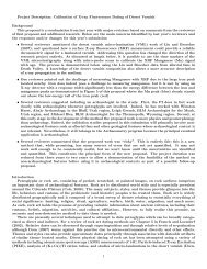
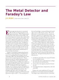
<strong>Fire</strong>-related debris flows initiated from several<br />
recently burned drainages on Dry Mountain in 2002<br />
<strong>and</strong> 2004. These flows inundated a subdivision near<br />
Santaquin (Figure 1) <strong>and</strong> caused $500,000 in damage<br />
to 32 homes.<br />
To minimize the risk to developments on alluvial<br />
fans, debris-flow mitigation structures may be required.<br />
Two types of mitigation structures are debrisflow<br />
basins <strong>and</strong> deflection berms. <strong>Debris</strong>-flow basins<br />
are closed structures that are designed to contain all or<br />
much of the volume of a debris flow. <strong>Deflection</strong> berms<br />
are open structures that are designed to direct debris<br />
flows toward low-risk areas on alluvial fans. Current<br />
technical literature describes different debris-flow<br />
mitigation structures <strong>and</strong> also presents equations <strong>for</strong><br />
the estimation of design parameters, but do not<br />
specifically outline how the design equations should<br />
be incorporated into the design of the structures. One<br />
of the few published systems, by Los Angeles (L.A.)<br />
County (Easton et al., 1979; Nasseri et al., 2006),<br />
includes st<strong>and</strong>ard procedures <strong>for</strong> the design of debrisflow<br />
basins <strong>and</strong> could benefit from several recent<br />
developments in debris-flow mitigation design. No<br />
guidelines exist <strong>for</strong> the design of debris-flow deflection<br />
berms; government agencies have been using design<br />
procedures that contain a degree of subjectivity <strong>and</strong><br />
could benefit from a more robust technical basis.<br />
This article first briefly summarizes debris-flow<br />
mitigation design aspects reported in the technical<br />
Environmental & Engineering Geoscience, Vol. XIV, No. 4, November 2008, pp. 297–313 297
Prochaska, Santi, <strong>and</strong> Higgins<br />
Figure 1. Inundation of a subdivision near Santaquin, Utah, by fire-related debris flows (from Elliot, 2007).<br />
literature. Next, a detailed review is presented of the<br />
design methodology <strong>for</strong> L.A. County debris basins<br />
(Easton et al., 1979; Nasseri et al., 2006) <strong>and</strong> the<br />
deflection berm design policies of the Oregon<br />
Department of Forestry (Hinkle, 2007) <strong>and</strong> the<br />
Natural Resources Conservation Service (NRCS)<br />
(Rogers, 2007). These procedures are some of the<br />
only published systems available <strong>and</strong> are fairly<br />
specific to the geology <strong>and</strong> conditions <strong>for</strong> which they<br />
were prepared. Finally, potential improvements <strong>for</strong><br />
these design methodologies with respect to recent<br />
developments in debris-flow mitigation design are<br />
presented, specifically <strong>for</strong> fire-related debris flows. A<br />
quantitative methodology <strong>for</strong> the design of deflection<br />
berms is also presented.<br />
BACKGROUND<br />
Discussion of various debris-flow mitigation structures<br />
can be found in several sources within the<br />
technical literature (Hungr et al., 1987; VanDine,<br />
1996; Fiebiger, 1997; VanDine et al., 1997; Heumader,<br />
2000; <strong>and</strong> Huebl <strong>and</strong> Fiebiger, 2005). Equations<br />
to aid in the design of these mitigation structures have<br />
been outlined by various authors (Hungr et al., 1984;<br />
VanDine, 1996; <strong>and</strong> Lo, 2000). However, none of<br />
these sources gives detailed guidelines as to how the<br />
debris-flow characteristics that are estimated from the<br />
design equations should be incorporated into the<br />
design of the mitigation structures.<br />
Giraud (2005) provides guidelines <strong>for</strong> evaluating the<br />
debris-flow hazard of areas, but focuses primarily on<br />
the geological aspects of debris-flow occurrence <strong>and</strong><br />
not on the actual design of mitigation. VanDine (1996)<br />
includes conceptual sketches of different mitigation<br />
structures, but does not provide a direct way of<br />
estimating the required size <strong>and</strong> strength of the<br />
conceptual structures based on properties of the debris<br />
flow. Sun <strong>and</strong> Lam (2004) provide a simplified<br />
methodology <strong>for</strong> the design of various debris flow<br />
barriers (concrete walls, gabions, <strong>and</strong> fences). Various<br />
possible locations <strong>for</strong> barrier placement are determined<br />
from the channel profile <strong>and</strong> the anticipated event<br />
volume. The required barrier size <strong>and</strong> strength at each<br />
location are also dependent on the design volume.<br />
However, this design method is limited to debris flows<br />
with volumes less than 600 m 3 (Sun <strong>and</strong> Lam, 2004).<br />
Bradley et al. (2005) discuss the design of debriscontrolling<br />
structures, but these designs are only<br />
applicable to debris carried by normal streamflow.<br />
Specific design methods <strong>for</strong> debris-flow basins <strong>and</strong><br />
deflection berms will be looked at in detail <strong>and</strong> are<br />
assumed to represent the state of practice in general.<br />
L.A. County has developed detailed manuals <strong>for</strong> the<br />
design of debris basins (Easton et al., 1979; Nasseri et<br />
al., 2006), but these manuals do not include several<br />
aspects of debris-flow mitigation design that are<br />
found in recent technical literature. In Oregon,<br />
deflection berms used in <strong>for</strong>ested regions are subjectively<br />
designed, using conservative qualitative judgment.<br />
The NRCS applies a bulking factor to clearwater<br />
flow to design the flow capacity of deflection<br />
berms. Several designers of other debris-flow mitigation<br />
structures recently constructed in Colorado were<br />
also contacted, but they declined to respond with<br />
their design methodologies.<br />
298 Environmental & Engineering Geoscience, Vol. XIV, No. 4, November 2008, pp. 297–313
<strong>Debris</strong>-Flow Mitigation <strong>Design</strong><br />
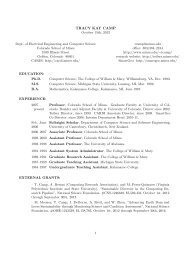
<strong>Debris</strong> Production curve; an example of the <strong>Debris</strong><br />
Production curves <strong>for</strong> the Los Angeles <strong>Basin</strong> is shown<br />
on Figure 4.<br />
In the simplest case of an undeveloped basin, the<br />
predicted debris-flow volume is equal to the drainage<br />
area multiplied by the <strong>Debris</strong> Production rate <strong>for</strong> the<br />
appropriate DPA. Nasseri et al. (2006) provide<br />
additional equations to obtain weighted-average<br />
predicted volumes <strong>for</strong> drainage basins that are<br />
partially developed, fall within multiple DPAs, or<br />
contain existing sediment control structures.<br />
<strong>Basin</strong> Siting <strong>and</strong> Sizing<br />
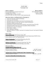
Figure 2. Photo of the Dewitt Canyon <strong>Debris</strong> <strong>Basin</strong> in L.A.<br />
County (courtesy of Ben Willardson).<br />
STATE OF PRACTICE FOR DEBRIS-FLOW<br />
BASIN DESIGN<br />
L.A. County has developed detailed manuals <strong>for</strong><br />
the design of debris-flow basins (Easton et al., 1979;<br />
Nasseri et al., 2006), which are the only readily<br />
available designs the authors could find. A photograph<br />
of the Dewitt Canyon <strong>Debris</strong> <strong>Basin</strong> in L.A.<br />
County, which was designed using the procedures<br />
outlined by Easton et al. (1979) <strong>and</strong> Nasseri et al.<br />
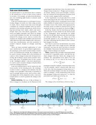
(2006), is shown in Figure 2. The main components of<br />
these basins are an earthen berm, a debris barrier, a<br />
spillway, <strong>and</strong> an outlet works, the general layout of<br />
which is shown in Figure 3. The published design<br />
procedures <strong>for</strong> each of these components are presented<br />
in upcoming sections. A predicted debris-flow<br />
volume is the primary event characteristic used <strong>for</strong><br />
sizing <strong>and</strong> siting the basin. L.A. County’s current<br />
method of estimating debris-flow volume is presented<br />
in the next section.<br />
Predicted <strong>Debris</strong>-Flow Volume<br />
L.A. County design manuals specify that a debrisflow<br />
basin is to have a capacity equal to the <strong>Design</strong><br />
<strong>Debris</strong> Event (DDE), which is the ‘‘quantity of<br />
sediment produced by a saturated watershed significantly<br />
recovered from a burn (after four years) as a<br />
result of a 50-year, 24-hour rainfall amount’’ (Nasseri<br />
et al., 2006). The DDE is estimated from the area of a<br />
drainage basin area <strong>and</strong> its <strong>Debris</strong> Production curve.<br />
L.A. County is divided into 11 different <strong>Debris</strong><br />
Production Areas (DPAs) based on local geologic,<br />
topographic, vegetative, <strong>and</strong> rainfall characteristics;<br />
these different DPAs are mapped in Appendix A of<br />
Nasseri et al. (2006). Each DPA has an associated<br />
Nasseri et al. (2006) provide an iterative technique<br />
through which the required height <strong>and</strong> location of the<br />
berm of a debris basin can be identified, based on the<br />
predicted debris-flow volume. This procedure is in<br />
agreement with other design recommendations<br />
(Hungr et al., 1987; VanDine, 1996; <strong>and</strong> Deganutti<br />
et al., 2003), <strong>and</strong> thus will not be discussed further.<br />
<strong>Debris</strong> <strong>Berm</strong> Specifications<br />
Easton et al. (1979) provide detailed specifications<br />
<strong>for</strong> the earthen berm of the debris basin. The berm is<br />
to have a crest width of 20 ft (6.1 m) <strong>and</strong> side slopes<br />
of 3:1 (horizontal:vertical). Steeper slopes are allowable<br />
if adequate stability is demonstrated when the<br />
berm is analyzed according to small-dam design<br />
criteria. The crest is specified to rise from the spillway<br />
walls to each abutment with a slope equal to 60<br />
percent of the natural channel slope within the basin.<br />
The upstream face of the berm is to be protected by a<br />
6-in. (15-cm) thick concrete slab with No. 5 rebar<br />
placed on 18-in. (46-cm) centers in both directions.<br />
The downstream face of the berm is specified to be<br />
seeded to protect against erosion. The horizontal<br />
length of the berm foundation should be sufficiently<br />
long to preclude piping.<br />
<strong>Debris</strong> Barrier Specifications<br />
Easton et al. (1979) specify that a debris barrier<br />
consisting of vertical members should be provided<br />
upstream of the spillway to prevent it from clogging<br />
with debris. The barrier is specified to be at least 6 ft<br />
(1.8 m) upstream of the spillway. The top of the<br />
barrier should be 1 ft (0.3 m) below the water<br />
surface elevation that would be required to pass<br />
the design water discharge through the spillway. At<br />
least 2 ft (0.6 m) of freeboard is required between<br />
this water surface elevation <strong>and</strong> the crest of the<br />
Environmental & Engineering Geoscience, Vol. XIV, No. 4, November 2008, pp. 297–313 299
Prochaska, Santi, <strong>and</strong> Higgins<br />
Figure 3. Layout of L.A. County’s debris basin components (not to scale) (after Easton et al., 1979): (a) Plan view, (b) Section A-A9, <strong>and</strong><br />
(c) Section A-B.<br />
debris berm. Horizontal spacings between barrier<br />
members are specified to be less than the lesser of<br />
4 ft (1.2 m) or two-thirds of the conduit width at the<br />
downstream end of the spillway. The barrier is<br />
specified to be designed <strong>for</strong> an equivalent fluid<br />
pressure of 62.5 lb/ft 2 (3.0 kPa) along its entire<br />
length (i.e., it is completely plugged). This load is<br />
assumed to be temporary, <strong>and</strong> thus the allowable<br />
stresses within the barrier members are increased by<br />
one-third. The depth of embedment of the barrier<br />
members is calculated as a function of the applied<br />
moment <strong>and</strong> the barrier diameter (Easton et al.,<br />
1979).<br />
Spillway Specifications<br />
Figure 4. <strong>Debris</strong> Production curves <strong>for</strong> the DPAs within the Los<br />
Angeles <strong>Basin</strong> (after Nasseri et al., 2006).<br />
Easton et al. (1979) provide specifications <strong>for</strong> the<br />
spillway capacity <strong>and</strong> also <strong>for</strong> the design of the<br />
300 Environmental & Engineering Geoscience, Vol. XIV, No. 4, November 2008, pp. 297–313
<strong>Debris</strong>-Flow Mitigation <strong>Design</strong><br />
Table 1. Freeboard <strong>and</strong> Factor of Safety recommendations (after FEMA, 1995).<br />
Type of Flooding Freeboard (ft) Impact Factor of Safety<br />
Shallow water flooding, ,1 ft 1 1.1<br />
Moderate water flooding, ,3 ft 1 1.2<br />
Moderate water flooding, ,3 ft with potential <strong>for</strong> debris, rocks ,1 ft diameter <strong>and</strong> sediment 1 1.2<br />
Mud floods, debris flooding ,3 ft, minor surging <strong>and</strong> deposition, ,1 ft boulders 2 1.25<br />
Mud flows, debris flows ,3 ft, surging, mud levees, .1 ft boulders, minor waves, deposition 2 1.4<br />
Mud <strong>and</strong> debris flows .3 ft, surging, waves, boulders .3 ft, major deposition 3 1.5<br />
Note: 1 ft 5 0.3 m.<br />
spillway walls <strong>and</strong> invert slab. This existing procedure<br />
designs the spillway <strong>for</strong> extreme flow events <strong>and</strong> is<br />
appropriate with respect to the Federal Emergency<br />
Management Agency’s (FEMA’s) (1995) freeboard<br />
recommendations (Table 1), <strong>and</strong> thus will not be<br />
discussed further.<br />
Outlet Works Specifications<br />
Easton et al. (1979) specify that the outlet works<br />
should consist of an outlet tower <strong>and</strong> an outlet pipe<br />
capable of passing 150 ft 3 /s (4.2 m 3 /s) via nonpressurized<br />
flow. The outlet tower should be located<br />
at the lowest point of the basin (but not within the<br />
direct path of flow between the basin inlet <strong>and</strong> the<br />
spillway) <strong>and</strong> should extend at least 1 ft (0.3 m) above<br />
the predicted surface of deposited debris within the<br />
basin. The outlet pipe is to be at least 36 in. (91 cm) in<br />
diameter <strong>and</strong> should have a slope greater than five<br />
percent to prevent siltation. Easton et al. (1979) <strong>and</strong><br />
L.A. County (2005) provide structural details <strong>for</strong> the<br />
st<strong>and</strong>ard outlet works design.<br />
Miscellaneous Specifications<br />
Easton et al. (1979) provide requirements <strong>for</strong><br />
engineering geology <strong>and</strong> subsurface investigations,<br />
<strong>and</strong> construction specifications <strong>and</strong> documentation.<br />
Detailed specifications are also given <strong>for</strong> access road<br />
grades <strong>and</strong> paving.<br />
Structures designed using the methodology presented<br />
by Easton et al. (1979) <strong>and</strong> Nasseri et al. (2006)<br />
have been meeting the expectations of L.A. County.<br />
However, issues are arising related to hydromodification,<br />
stream degradation, <strong>and</strong> regulatory concerns<br />
related to preserving natural systems (Willardson,<br />
2008).<br />
PROPOSED CHANGES TO THE STATE OF<br />
PRACTICE FOR DEBRIS-FLOW BASIN DESIGN<br />
The intent of this paper is not to critique the<br />
design procedures published by L.A. County<br />
(Easton et al., 1979; Nasseri et al., 2006), as these<br />
publications represent a great step <strong>for</strong>ward in debrisflow<br />
mitigation engineering. However, as some of<br />
the only publications containing detailed design<br />
in<strong>for</strong>mation, they serve as a representation of the<br />
state of practice in general <strong>and</strong> can be used as a<br />
springboard <strong>for</strong> discussion. The observations that<br />
follow should be taken as comments on the state of<br />
practice in a newly developing field <strong>and</strong> not as<br />
critiques of the pioneering work done by L.A.<br />
County. The following sections comment on potential<br />
changes to debris-basin design procedures when<br />
viewed in the context of debris-flow design recommendations<br />
presented within the technical literature.<br />
These suggestions particularly address the mitigation<br />
of fire-related debris flows <strong>and</strong> the adaptation<br />
of the design methodologies to regions beyond those<br />
used in their development. The following suggested<br />
changes to the prediction of debris-flow volume <strong>and</strong><br />
prioritization of mitigation ef<strong>for</strong>ts are specific to<br />
fire-related debris flows, whereas the remaining<br />
suggestions are also applicable to non-fire-related<br />
debris flows.<br />
Predicted <strong>Debris</strong>-Flow Volume<br />
A predicted debris-flow volume is a rational basis<br />
<strong>for</strong> basin design, since volume will dictate the capacity<br />
of the structure <strong>and</strong> is also a good indicator of the<br />
event hazard (Jakob, 2005; Cannon, 2007). Although<br />
Nasseri et al. (2006) acknowledge that recently<br />
burned drainage basins have higher sediment production<br />
(i.e., debris-flow volumes) than unburned basins,<br />
the <strong>Debris</strong> Production curves from which a DDE is<br />
estimated are based only on sediment production<br />
from unburned drainage basins (Nasseri et al., 2006).<br />
In areas susceptible to wildfires, the expected<br />
debris-flow volume from a recently burned watershed<br />
should also be considered. Even if a debris basin is<br />
being designed below an unburned drainage basin, it<br />
would be prudent to consider the debris-flow volume<br />
that could result if the drainage burned. Two<br />
empirical methods <strong>for</strong> the estimation of post-wildfire<br />
debris-flow volumes are discussed below.<br />
Environmental & Engineering Geoscience, Vol. XIV, No. 4, November 2008, pp. 297–313 301
The Los Angeles District of the U.S. Army Corps<br />
of Engineers has developed empirical relationships <strong>for</strong><br />
the estimation of debris production from recently<br />
burned, coastal-draining, mountainous, Southern<br />
Cali<strong>for</strong>nia drainage basins (Gatwood et al., 2000).<br />
For drainage basins between 0.1 mi 2 <strong>and</strong> 3.0 mi 2 (0.3<br />
to 7.8 km 2 ) in area, the debris production may be<br />
estimated by:<br />
Prochaska, Santi, <strong>and</strong> Higgins<br />
logDy~0:65(logP)z0:62(logRR)<br />
z0:18(logA)z0:12(FF)<br />
ð1Þ<br />
where Dy 5 debris yield (yd 3 /mi 2 ), P 5 maximum<br />
1-hour precipitation (hundredths of an in.), RR 5<br />
drainage basin relief ratio (ft/mi), A 5 drainage basin<br />
area (acres), <strong>and</strong> FF 5 non-dimensional <strong>Fire</strong> Factor<br />
(discussed below). Note that 1 yd 3 /mi 2 5 0.29 m 3 /<br />
km 2 ; 0.01 in. 5 0.25 mm; 1 ft/mi 5 0.19 m/km; <strong>and</strong> 1<br />
acre 5 0.004 km 2 .<br />
Eq. 1 was developed from nearly 350 observations<br />
<strong>and</strong> has a coefficient of determination of 0.99. For<br />
drainage basins less than 10 mi 2 (26 km 2 ) in area <strong>for</strong><br />
which peak flow data are available, the debris<br />
production may be estimated by (Gatwood et al.,<br />
2000):<br />
logDy~0:85(logQ)z0:53(logRR)<br />
z0:04(logA)z0:22(FF)<br />
ð2Þ<br />
where Q 5 unit peak flow (ft 3 /s/mi 2 )(1ft 3 /s/mi 2 5<br />
0.01 m 3 /s/km 2 ) <strong>and</strong> all other variables are as defined<br />
in Eq. 1.<br />
The <strong>Fire</strong> Factor used in Eq. 1 <strong>and</strong> 2 is different<br />
from the <strong>Fire</strong> Factor used in other L.A. County<br />
analyses (e.g., Willardson <strong>and</strong> Walden, 2003). <strong>Fire</strong><br />
Factors used by the U.S. Army Corps of Engineers<br />
<strong>for</strong> debris production estimates range from 3.0 <strong>for</strong><br />
unburned or fully recovered watersheds to 6.5 <strong>for</strong><br />
watersheds that recently have been completely<br />
burned (100-percent wildfire). These <strong>Fire</strong> Factors<br />
can be estimated as a function of watershed size<br />
<strong>and</strong> time since a 100-percent burn by using<br />
Figures 5 or 6. For drainage basins that are only<br />
partially burned, a weighted average of the <strong>Fire</strong><br />
Factor is obtained based on the percentage of the<br />
basin that has been burned <strong>and</strong> the time since the<br />
burn(s), as presented in Appendix A of Gatwood et<br />
al. (2000).<br />
Gartner et al. (2007) developed empirical models to<br />
predict debris-flow volumes from recently burned<br />
drainage basins in the western United States. The best<br />
model obtained from 50 debris-flow events in Colorado,<br />
Utah, <strong>and</strong> Cali<strong>for</strong>nia was<br />
Figure 5. <strong>Fire</strong> Factor curve <strong>for</strong> watersheds between 0.1 <strong>and</strong><br />
3.0 mi 2 (0.26 <strong>and</strong> 7.8 km 2 ) (after Gatwood et al., 2000).<br />
lnV~0:59(lnS 30 )z0:65(B) 1=2 z0:18(R) 1=2 z7:21<br />
ð3Þ<br />
where V 5 debris-flow volume (m 3 ), S 30 5 basin area<br />
with slopes greater than or equal to 30 percent (km 2 ),<br />
B 5 basin area burned at moderate <strong>and</strong> high severity<br />
(km 2 ), <strong>and</strong> R 5 total storm rainfall (mm).<br />
Eq. 3 has a coefficient of determination of 0.83 <strong>and</strong><br />
a residual st<strong>and</strong>ard error of 0.79 ln m 3 (Gartner et al.,<br />
2007).<br />
For coastal Southern Cali<strong>for</strong>nia drainages, the<br />
larger of the volumes obtained from the Corps of<br />
Engineers method (Gatwood et al., 2000) (Eq. 1 or 2)<br />
<strong>and</strong> the method of Gartner et al. (2007) (Eq. 3) could<br />
be used <strong>for</strong> design. The Corps of Engineers method<br />
will likely produce more accurate results within this<br />
region because these equations have higher coefficients<br />
of determination <strong>and</strong> are based on more<br />
observations than the method of Gartner et al.<br />
(2007). When applying the Corps of Engineers<br />
methods, it would be prudent to use a conservative<br />
<strong>Fire</strong> Factor to estimate volume, because a drainage<br />
basin may potentially become more extensively<br />
burned than its current condition. The development<br />
of Eq. 3 included debris-flow events from the Rocky<br />
Mountains, <strong>and</strong> thus this model would be more<br />
broadly applicable to regions outside of Southern<br />
Cali<strong>for</strong>nia. Gartner et al. (2007) also consider burn<br />
severity in their volume prediction model <strong>and</strong> provide<br />
an estimate of modeling error.<br />
<strong>Debris</strong> <strong>Berm</strong> Specifications<br />
A berm crest that slopes toward the spillway is in<br />
agreement with other debris-flow basin design recommendations<br />
(Hungr et al., 1987). This will<br />
encourage any overflow to pass through the spillway<br />
302 Environmental & Engineering Geoscience, Vol. XIV, No. 4, November 2008, pp. 297–313
<strong>Debris</strong>-Flow Mitigation <strong>Design</strong><br />
Figure 6. <strong>Fire</strong> Factor curves <strong>for</strong> watersheds between 3.0 <strong>and</strong> 200 mi 2 (7.8 <strong>and</strong> 520 km 2 ) (after Gatwood et al., 2000).<br />
rather than to overtop the dam, which will help to<br />
protect the berm from scour.<br />
The recommended upstream slope of 3:1 (horizontal:vertical)<br />
may be overly conservative, given the low<br />
heights to which many debris basins will be constructed.<br />
Upstream slope stability is also aided by the<br />
specified rein<strong>for</strong>ced concrete slab. A steeper upstream<br />
slope would require less fill placement during<br />
construction <strong>and</strong> would also result in greater basin<br />
capacity. Nasseri et al. (2006) report that several<br />
debris basins have experienced momentum overflow<br />
(i.e., overtopping) of the structure be<strong>for</strong>e the basins<br />
were filled. A steeper upstream slope may help to<br />
alleviate this problem as well.<br />
Because laboratory soil strength testing is already<br />
required by Section B of Easton et al. (1979), it would<br />
not be overly difficult to conduct slope stability<br />
analyses. Instead of relying on a blanket specification<br />
<strong>for</strong> a 3:1 slope, the steepest upstream slope that<br />
satisfies all of the design criteria could be used.<br />
The phenomenon that Nasseri et al. (2006) refer to<br />
as ‘‘momentum overflow’’ is better known in the<br />
debris-flow literature as runup. Runup is the ability of<br />
a debris flow to climb an adverse slope due to its<br />
momentum. If the runup height of a debris flow<br />
exceeds the berm height, overtopping is predicted to<br />
occur. Once a debris basin has been sized following<br />
the procedures outlined above, it should be checked<br />
that the berm is sufficiently high to resist debris-flow<br />
runup.<br />
A commonly advocated runup prediction method<br />
(Hungr et al., 1984; Hungr <strong>and</strong> McClung, 1987;<br />
VanDine, 1996; <strong>and</strong> Lo, 2000) that has accurately<br />
matched laboratory experiments (Chu et al., 1995) is<br />
the leading-edge model:<br />
Dh~ v2 cos 2 <br />
(h 0 zh) tan h<br />
1z gh cos h 2<br />
0<br />
ð4Þ<br />
g(S f z tan h)<br />
2v 2<br />
where: Dh 5 runup height, v 5 debris-flow velocity,<br />
h 0 5 approach slope angle, h 5 runup slope angle<br />
(berm slope), g 5 acceleration of gravity, S f 5 friction<br />
slope, <strong>and</strong> h 5 debris-flow depth, all in consistent<br />
units.<br />
For runup estimations, the friction slope (S f ) may<br />
be adequately estimated as 1.1 times the tangent of<br />
the alluvial fan slope (Rickenmann, 2005). Prochaska<br />
et al. (2008b) discuss a new method <strong>for</strong> the estimation<br />
of debris-flow velocity <strong>and</strong> the maximum probable<br />
debris-flow depth, which can be used in Eq. 4. A<br />
maximum possible flow depth, h, may be estimated as<br />
the height from bedrock to the top of the channel<br />
banks. This estimate conservatively assumes that,<br />
during a debris flow, the channel has been scoured<br />
down to bedrock <strong>and</strong> the channel is flowing full. An<br />
increase in flow depth above the height of the channel<br />
banks will cause material to spill over <strong>and</strong> deposit due<br />
to lack of confinement, effectively limiting the<br />
maximum potential flow depth. A debris flow velocity<br />
can be predicted preliminarily from the flow depth (h)<br />
Environmental & Engineering Geoscience, Vol. XIV, No. 4, November 2008, pp. 297–313 303
Prochaska, Santi, <strong>and</strong> Higgins<br />
Table 2. Summary of velocity versus h 2 S data (from Prochaska et al., 2008b).<br />
h 2 S , 3m 2 3m 2 , h 2 S , 6m 2 6m 2 , h 2 S<br />
Mean – 1 st<strong>and</strong>ard deviation 3.7 m/s 4.5 m/s 7.0 m/s<br />
Mean 6.0 m/s 6.8 m/s 10.4 m/s<br />
Mean + 1 st<strong>and</strong>ard deviation 8.3 m/s 9.1 m/s 13.8 m/s<br />
Mean + 2 st<strong>and</strong>ard deviations 10.6 m/s 11.4 m/s 17.2 m/s<br />
<strong>and</strong> the sine of the channel angle (S) using Table 2.<br />
This table was developed from a statistical analysis of<br />
30 debris-flow events from the technical literature<br />
(Prochaska et al., 2008b).<br />
No debris-berm freeboard heights are recommended<br />
by Easton et al. (1979) or Nasseri et al. (2006).<br />
Given the inherent uncertainties with debris-flow<br />
volume estimations <strong>and</strong> flow mechanics, it would<br />
seem prudent to provide an additional factor of safety<br />
to the basin capacity through a minimum freeboard<br />
requirement.<br />
FEMA provides recommended freeboard heights<br />
<strong>for</strong> various categories of floods (Table 1) (FEMA,<br />
1995). From Table 1, a required freeboard of at least<br />
3 ft (0.9 m) should be provided above either the<br />
spillway elevation of the debris berm or the predicted<br />
height of runup (Eq. 4), whichever is higher. This<br />
freeboard height is comparable to those used in<br />
previous designs (Nasmith <strong>and</strong> Mercer, 1979; Van-<br />
Dine, 1996).<br />
<strong>Debris</strong> Barrier Specifications<br />
The design of the debris barrier appears to only<br />
consider the loading from water <strong>and</strong> not the impact<br />
from any debris, which is unconservative. Also, the<br />
recommended barrier spacing does not account <strong>for</strong><br />
the site-specific debris gradation.<br />
The debris barrier should be designed to withst<strong>and</strong><br />
loading from the retained debris. <strong>Debris</strong> impact loads<br />
can either be estimated analytically through the loss<br />
of momentum or empirically related to hydrostatic<br />
<strong>for</strong>ces. A commonly advocated analytical equation<br />
<strong>for</strong> the estimation of impact <strong>for</strong>ce is (Hungr et al.,<br />
1984; VanDine, 1996; <strong>and</strong> Lo, 2000):<br />
can be much larger than those predicted by Eq. 5<br />
because of the shear strength of debris <strong>and</strong> reflection<br />
waves occurring upon impact (Lin et al., 1997; Lo,<br />
2000). Figure 7 shows a histogram of field-measured<br />
impact <strong>for</strong>ces normalized by the impact <strong>for</strong>ces<br />
calculated by Eq. 5 <strong>for</strong> 24 debris-flow measurements<br />
from China (Lo, 2000). The data summarized on<br />
Figure 7 have a mean of 3.0 <strong>and</strong> a st<strong>and</strong>ard<br />
deviation of 1.3. Lo (2000) recommends multiplying<br />
Eq. 5 by a factor of three to obtain a design impact<br />
<strong>for</strong>ce.<br />
The debris impact <strong>for</strong>ce can also be empirically<br />
estimated by factoring a hydrostatic load (Lo, 2000):<br />
F d ~ x c w h 2<br />
2<br />
ð6Þ<br />
where F d 5 debris impact <strong>for</strong>ce per unit width of<br />
analysis, x 5 load factor, c w 5 unit weight of water,<br />
<strong>and</strong> h 5 debris-flow depth, all in consistent units.<br />
The load factor (x) in Eq. 6 has been recommended<br />
as being between approximately three <strong>and</strong> five<br />
(Scotton <strong>and</strong> Deganutti, 1997; Lo, 2000). Hollingsworth<br />
<strong>and</strong> Kovacs (1981) advise using an equivalent<br />
unit weight of 125 lb/ft 3 (19.7 kN/m 3 ) <strong>for</strong> debris<br />
loads, which would make x equal to two. Because<br />
of this range of suggested load factor values, a<br />
conservative load factor toward the high end of the<br />
presented ranges should be used. The flow velocity<br />
F d ~h r v 2 sin d<br />
ð5Þ<br />
where F 5 debris impact <strong>for</strong>ce per unit width of<br />
analysis, h 5 debris-flow depth, r 5 debris density, v<br />
5 debris-flow velocity, <strong>and</strong> d 5 acute angle between<br />
flow velocity vector <strong>and</strong> impacted surface, all in<br />
consistent units.<br />
Eq. 5 assumes that the debris has zero strength.<br />
Field instrumentation <strong>and</strong> laboratory simulation of<br />
debris-flow impacts have shown that actual <strong>for</strong>ces<br />
Figure 7. Histogram of the ratios of field-measured impact <strong>for</strong>ces<br />
to impact <strong>for</strong>ces calculated by Eq. 5 (data are from Lo, 2000).<br />
304 Environmental & Engineering Geoscience, Vol. XIV, No. 4, November 2008, pp. 297–313
<strong>Debris</strong>-Flow Mitigation <strong>Design</strong><br />
<strong>and</strong> depth required <strong>for</strong> debris impact <strong>for</strong>ce equations<br />
(Eq. 5 <strong>and</strong> 6) can be estimated as presented in Table 2<br />
<strong>and</strong> discussed by Prochaska et al. (2008b).<br />
In addition to debris impact <strong>for</strong>ces, the debris<br />
barrier should also be designed to withst<strong>and</strong> boulder<br />
impact <strong>for</strong>ces. For cantilever steel members in a<br />
debris barrier, the flexural stiffness equation would be<br />
most appropriate (Hungr et al., 1984; Johnson <strong>and</strong><br />
McCuen, 1992; <strong>and</strong> Lo, 2000):<br />
p<br />
F~v b sin b<br />
ffiffiffiffiffiffiffiffiffiffiffiffi<br />
m b K B<br />
ð7aÞ<br />
K B ~<br />
3EI<br />
(YL B ) 3 <strong>for</strong> a cantilever beam or wall ð7bÞ<br />
where F 5 impact <strong>for</strong>ce (MN), v b 5 boulder velocity<br />
(m/s), b 5 acute angle between the velocity vector <strong>and</strong><br />
the barrier surface, m b 5 boulder mass (Mg), EI 5<br />
bending stiffness of barrier (GPa*m 4 ), L B 5 length or<br />
height of barrier (m), <strong>and</strong> Y 5 ratio of distance<br />
between the impact location <strong>and</strong> barrier support to<br />
the length of the barrier.<br />
The boulder velocity <strong>for</strong> use in Eq. 7 should be equal<br />
to the predicted debris-flow velocity, <strong>and</strong> the size of the<br />
design boulder should be based on the available sizes of<br />
transportable material (Hungr et al., 1984; Lo, 2000).<br />
Once the maximum impact <strong>for</strong>ce from Eq. 5, 6, <strong>and</strong> 7 is<br />
decided upon <strong>for</strong> design, this load should be increased<br />
by a factor of safety of 1.5 (Table 1).<br />
Consideration of the site-specific debris gradation<br />
can also be incorporated into the recommended barrier<br />
spacings. In Japan, barriers are typically spaced at 1.5<br />
to 2 times the size of the largest boulders (VanDine,<br />
1996; Miyazawa et al., 2003). Barrier spacings used in<br />
model tests also fall within this range (Chen <strong>and</strong> Ho,<br />
1997). This requirement could be added to the barrier<br />
spacing specifications presented previously. Channelspecific<br />
maximum particle sizes could be estimated<br />
through investigations of the sizes of material present<br />
within the channel <strong>and</strong> source areas, <strong>and</strong> also the sizes<br />
of boulders previously deposited on the fan. This<br />
evaluation of maximum particle size is also required <strong>for</strong><br />
the estimation of boulder impact <strong>for</strong>ces (Eq. 7).<br />
Outlet Works Specifications<br />
Easton et al. (1979) <strong>and</strong> L.A. County (2005)<br />
provide one st<strong>and</strong>ard outlet works design <strong>for</strong> all<br />
constructed basins, <strong>and</strong> it may be more practical to<br />
provide a few different st<strong>and</strong>ard designs from which<br />
to choose. Specifically, different designs should<br />
address the ability of the outlet works to convey<br />
different levels of flow <strong>and</strong> the resistance of the outlet<br />
tower to various magnitudes of impact <strong>for</strong>ces.<br />
Because Easton et al. (1979) specify that the debris<br />
barrier should be designed <strong>for</strong> loads from only clear<br />
water flow, it is likely that the st<strong>and</strong>ard design <strong>for</strong> the<br />
outlet tower also does not consider debris-flow<br />
impact <strong>for</strong>ces. It should be verified that the existing<br />
or any future design has an appropriate factor of<br />
safety (Table 1) against the debris impact <strong>for</strong>ces<br />
predicted by Eq. 5 <strong>and</strong> 6 <strong>and</strong> the boulder impact<br />
<strong>for</strong>ces predicted by Eq. 7.<br />
Different outlet works designs should be developed<br />
<strong>for</strong> different expected impact <strong>for</strong>ces. The<br />
existing st<strong>and</strong>ard design (L.A. County, 2005) could<br />
be used as a generic template, with specific<br />
dimensions <strong>and</strong> notes obtainable from a table based<br />
on the expected flow depth, velocity, <strong>and</strong> boulder<br />
sizes. Each design should provide a factor of safety<br />
of at least 1.5 against the expected <strong>for</strong>ces (Table 1).<br />
These different designs could also provide various<br />
flow capacities within the range of discharges<br />
observed from the region’s debris-flow-producing<br />
drainage basins.<br />
Miscellaneous Specifications<br />
An important aspect of apportioning emergency<br />
mitigation ef<strong>for</strong>ts is the likelihood of an individual<br />
basin to produce a debris flow. Cannon (2001) found<br />
that debris flows were not the prevalent response <strong>for</strong><br />
95 recently burned drainage basins in Colorado, New<br />
Mexico, <strong>and</strong> Cali<strong>for</strong>nia. Only approximately 40<br />
percent of these basins produced debris flows as their<br />
initial erosive response, <strong>and</strong> only one basin produced<br />
a debris flow in a subsequent erosional event<br />
(Cannon, 2001). Thus, in order to efficiently allocate<br />
mitigation funds, the likelihood of individual drainage<br />
basins to produce debris flows should be<br />
estimated, along with the associated hazard <strong>and</strong> risk<br />
in the event that a debris flow does occur.<br />
The U.S. Geological Survey has developed an<br />
empirical relationship to estimate the probability of<br />
fire-related debris-flow occurrence from individual<br />
basins (Cannon et al., 2003; 2004a; 2004b):<br />
P~ ex<br />
1ze x<br />
x~{29:693z10:697(%Burn){9:875(Sorting)<br />
z0:208(I)z5:729(%Organics){0:957<br />
(Permeability)z9:351(Drainage)<br />
z2:864(%GE30%){8:335(%Burn %Organics)<br />
ð8aÞ<br />
ð8bÞ<br />
z4:669(Sorting Drainage){0:174(%GE30% I)<br />
Environmental & Engineering Geoscience, Vol. XIV, No. 4, November 2008, pp. 297–313 305
Prochaska, Santi, <strong>and</strong> Higgins<br />
<strong>Design</strong> Aspect<br />
Event volume<br />
Table 3. Summary of proposed changes to existing berm designs.<br />
State of Practice (Easton et al.,<br />
1979; Nasseri et al., 2006) Proposed Changes<br />
Sediment production from<br />
unburned drainage following<br />
50-year, 24-hour rainfall<br />
Consider sediment production<br />
from burned drainage basin<br />
<strong>Berm</strong> slopes 3H:1V Use steepest slopes that satisfy<br />
all design criteria<br />
Runup height Not specified <strong>Design</strong> berm height <strong>for</strong> anticipated debris-flow runup<br />
<strong>Berm</strong> freeboard Not specified Provide 3 ft (0.9 m) of freeboard as per FEMA (1995)<br />
<strong>Debris</strong> barrier spacing<br />
Lesser of 4 ft (1.2 m) or 2/3 of Base spacing on site-specific debris gradation<br />
downstream conduit width<br />
<strong>Debris</strong> barrier loading <strong>Design</strong>ed <strong>for</strong> water load Consider loading from debris<br />
impacts <strong>and</strong> boulder impacts<br />
Outlet works capacity 150 ft 3 /s (4.2 m 3 /s) Provide various designs to accommodate site-specific<br />
streamflow<br />
Outlet works loading Not specified Consider loading from debris impacts <strong>and</strong> boulder impacts<br />
Mitigation apportioning Not specified Consider debris-flow probability <strong>and</strong> associated hazards <strong>and</strong><br />
risk to allocate mitigation funds<br />
where P 5 probability of debris-flow occurrence,<br />
%Burn 5 percent of the basin burned at high <strong>and</strong><br />
moderate severities, Sorting 5 sorting of the burned<br />
soil grain-size distribution (Inman, 1952), I 5 average<br />
storm rainfall intensity (mm/hr), %Organics 5<br />
percent of soil organic matter, Permeability 5 soil<br />
permeability (in./hr) (Schwartz <strong>and</strong> Alex<strong>and</strong>er, 1995),<br />
Drainage 5 soil drainage (Schwartz <strong>and</strong> Alex<strong>and</strong>er,<br />
1995), <strong>and</strong> %GE30% 5 percent of the basin with<br />
slopes greater than or equal to 30 percent. Note: 1 in./<br />
hr 5 25.4 mm/hr.<br />
The debris-flow hazard <strong>for</strong> an individual basin can<br />
be estimated from its predicted volume <strong>and</strong> expected<br />
runout distance or inundation area. A predicted firerelated<br />
debris-flow volume can be estimated from<br />
Eq. 3. Runout or inundated area can be estimated<br />
from the ACS model (Prochaska et al., 2008a), from<br />
other existing runout estimation methods discussed<br />
by Prochaska et al. (2008a), or from developing<br />
models specific to fire-related debris flows (i.e.,<br />
Bernard, 2007). Once a hazardous area has been<br />
delineated, the associated risk can be estimated from<br />
the value of the property within it. This value should<br />
consider the amount <strong>and</strong> types of development, the<br />
presence of human occupancy, <strong>and</strong> the importance of<br />
transportation corridors. <strong>Debris</strong>-flow consequence<br />
can then be estimated <strong>and</strong> ranked by multiplying<br />
each basin’s risk by its probability of debris-flow<br />
occurrence (Eq. 8).<br />
Table 3 summarizes the proposed changes to the<br />
state of practice <strong>for</strong> debris-flow basin design, as<br />
presented by Easton et al. (1979) <strong>and</strong> Nasseri et al.<br />
(2006). These changes will likely result in increased<br />
mitigation costs, the amount of which will be sitespecific.<br />
The additional cost would likely be offset by<br />
the higher safety provided by the increased mitigation<br />
effectiveness.<br />
STATE OF PRACTICE FOR DEBRIS-FLOW<br />
DEFLECTION BERM DESIGN<br />
Oregon Department of Forestry <strong>Deflection</strong><br />
<strong>Berm</strong> <strong>Design</strong><br />
The Oregon Department of Forestry has overseen<br />
the construction of deflection berms to mitigate<br />
debris-flow hazards below logged watersheds. Rather<br />
than per<strong>for</strong>ming detailed analyses, qualitative judgment<br />
is conservatively applied to develop an ‘‘overengineered’’<br />
design. The berms are constructed at low<br />
angles (with respect to the natural flow path),<br />
oversized, <strong>and</strong> armored with large rocks to avoid<br />
the issues of calculating runup <strong>and</strong> impact <strong>for</strong>ces<br />
(Hinkle, 2007). <strong>Deflection</strong> berms designed using this<br />
methodology have not yet been tested by debris-flow<br />
events (Hinkle, 2008).<br />
NRCS <strong>Deflection</strong> <strong>Berm</strong> <strong>Design</strong><br />
The NRCS office in Provo, Utah, has recently<br />
designed deflection berms <strong>for</strong> the mitigation of firerelated<br />
debris flows from Buckley Draw in Provo <strong>and</strong><br />
Tributary 4 in Santaquin (McDonald <strong>and</strong> Giraud,<br />
2002). Figure 8 shows a downstream view of the<br />
Buckley Draw deflection berm near Provo, Utah,<br />
following a small debris flow.<br />
To size the deflection berms, the Provo NRCS first<br />
estimated the peak clear-water discharge from each<br />
basin using conventional hydrological methods (e.g.,<br />
Brutsaert, 2005). The 25-year, 24-hour precipitation<br />
306 Environmental & Engineering Geoscience, Vol. XIV, No. 4, November 2008, pp. 297–313
<strong>Debris</strong>-Flow Mitigation <strong>Design</strong><br />
Figure 8. Downstream view of the Buckley Draw deflection berm near Provo, Utah, after a small debris flow (from Elliot, 2007).<br />
was used <strong>for</strong> the design of the Buckley Draw<br />
deflection berm. A bulking factor was then applied<br />
to the clear-water discharge to account <strong>for</strong> the debrisflow<br />
peak discharge. For Buckley Draw, a bulking<br />
factor of approximately 1.4 was used. This bulking<br />
factor was estimated using an unpublished Engineering<br />
Technical Note developed by the NRCS in New<br />
Mexico that discusses soil erodibility. Additional<br />
conservatism <strong>and</strong> freeboard were added to the berm<br />
height above that required to pass the design<br />
discharge. Superelevation heights were also considered,<br />
<strong>and</strong> the upstream side of the berm was armored<br />
with large rocks (Rogers, 2007).<br />
Structures designed using this methodology have<br />
settled out coarse material from debris flows, with<br />
only water <strong>and</strong> some fines exiting the structure<br />
(Rogers, 2008).<br />
PROPOSED CHANGES TO THE STATE OF<br />
PRACTICE FOR DEBRIS-FLOW DEFLECTION<br />
BERM DESIGN<br />
As with the critique of debris-flow basin design, the<br />
few published designs <strong>for</strong> debris-flow deflection berms<br />
are assumed to represent the state of practice in general.<br />
These published designs represent the <strong>for</strong>efront of a<br />
field that is newly developing, <strong>and</strong> the comments below<br />
are aimed at improving the state of practice <strong>and</strong> not at<br />
disparaging these designs.<br />
Discussion<br />
Because Oregon’s Department of Forestry policy of<br />
developing conservative deflection berm designs from<br />
qualitative judgment is, by definition, subjective, it<br />
may be difficult to assess exactly what constitutes a<br />
conservative design. In order to deem a design<br />
conservative, one must have an idea of the berm size<br />
that is required to provide debris-flow control. This<br />
knowledge may come from the precedent of the<br />
successes or failures of previous structures or from a<br />
quantitative estimate of the characteristics of a design<br />
debris-flow event. Upcoming sections provide a<br />
methodology <strong>for</strong> the quantitative design of debrisflow<br />
deflection berms.<br />
Although the NRCS designs deflection berms <strong>for</strong> a<br />
quantitative discharge, the reliance on an erodibility<br />
study from New Mexico introduces some variability.<br />
First, the applicability of this study to Utah is difficult<br />
to prove because of possible geologic, meteorologic,<br />
<strong>and</strong> vegetative differences between the two states.<br />
Second, it is uncertain whether the New Mexico<br />
erodibility study considered scouring effects of debris<br />
flows or if it was only applicable to the bulking of<br />
sediment into normal stream flow. Bulking rates<br />
observed once debris flows occur will be higher than<br />
those associated with clear-water flow due to the<br />
increased shear stress caused by a higher fluid density<br />
(Hungr et al., 2005).<br />
Environmental & Engineering Geoscience, Vol. XIV, No. 4, November 2008, pp. 297–313 307
Prochaska, Santi, <strong>and</strong> Higgins<br />
L.A. County has developed bulking factors to<br />
estimate bulked discharge from water discharge<br />
(Nasseri et al., 2006), which also introduces imprecision.<br />
The same bulking factor is applied to both<br />
burned <strong>and</strong> unburned drainage basins, when in<br />
reality a much higher sediment yield should be<br />
expected from burned drainages (Cannon <strong>and</strong><br />
Gartner, 2005).<br />
As discussed in the next section, a simpler method<br />
<strong>for</strong> specifying the flow capacity of a deflection berm<br />
would be to ensure that it is capable of passing at least<br />
as much flow as the channel immediately upstream<br />
from it.<br />
Proposed Guidelines<br />
This section presents proposed guidelines <strong>for</strong> the<br />
design of debris-flow deflection berms. These guidelines<br />
would be applicable to both fire-related debris<br />
flows <strong>and</strong> non-fire-related debris flows. <strong>Deflection</strong><br />
structures may consist of either earthen berms or<br />
structural walls (Mears, 1981), depending on material<br />
availability. This section focuses on the design of<br />
earthen deflection berms.<br />
<strong>Berm</strong> Siting <strong>and</strong> Alignment<br />
The primary consideration <strong>for</strong> the design of<br />
deflection berms is the siting <strong>and</strong> alignment of the<br />
structure. <strong>Deflection</strong> berms will be most effective<br />
when they are located high on alluvial fans. <strong>Debris</strong><br />
flows here will have higher velocities than at locations<br />
lower on fans; these higher velocities will encourage<br />
debris to pass through the deflection berm rather than<br />
depositing within it <strong>and</strong> reducing the effective height<br />
of the structure (Mears, 1981). Siting deflection berms<br />
higher on alluvial fans also enables more area to be<br />
protected, <strong>and</strong> placing a berm closer to the mountain<br />
channel lessens the chance that a debris flow could<br />
avulse <strong>and</strong> bypass the structure. However, in some<br />
cases high debris-flow velocities at the mouths of<br />
channels may make mitigation too difficult (Nasmith<br />
<strong>and</strong> Mercer, 1979), <strong>and</strong> thus berms would have to be<br />
placed lower on the fan to allow the debris flow to<br />
decelerate.<br />
<strong>Deflection</strong>-berm alignments can be straight,<br />
curved, or a combination of the two (Mears, 1981).<br />
The siting <strong>and</strong> alignment of individual deflections<br />
berms will vary based on several site-specific considerations,<br />
including:<br />
N The natural alignment of the stream course, <strong>and</strong> the<br />
drainage characteristics of the area.<br />
N The topography of the alluvial fan.<br />
N The location of the areas to be protected.<br />
N The location of low-risk areas to where the debris<br />
can be directed.<br />
N The anticipated characteristics of the design debrisflow<br />
event.<br />
When designing the alignment of the berm, specific<br />
attention must be paid to where the debris flow <strong>and</strong><br />
normal streamflow are to be directed. Consideration<br />
must be made of how the debris-flow hazard <strong>and</strong> risk<br />
to the surrounding area will change due to the<br />
deflection of the natural debris path. The deflection<br />
of the debris flow may decrease or increase its runout<br />
length <strong>and</strong> inundation area, depending on site-specific<br />
characteristics. VanDine (1996) reported that deflection<br />
berms can be aligned at low gradients to<br />
encourage deposition <strong>and</strong> reduce the runout length<br />
of debris flows. However, deflection berms may<br />
instead provide additional confinement to flowing<br />
debris <strong>and</strong> thus increase the runout length (Mears,<br />
1981). If the deflection structure is contiguous with<br />
the mountain front <strong>and</strong> normal streamflow will be<br />
contained behind the berm, then provisions must also<br />
be made to safely direct this flow back into a natural<br />
drainage.<br />
<strong>Berm</strong> Height Sizing<br />
After the location <strong>and</strong> alignment of the deflection<br />
berm is decided upon, it must be appropriately sized.<br />
The berm should be high enough to pass the<br />
discharge from the design debris-flow event, with<br />
consideration given to superelevation <strong>and</strong> runup<br />
heights <strong>and</strong> an appropriate freeboard, or<br />
h B ~hzDhz3ft<br />
ð9Þ<br />
where h B 5 height of debris-flow deflection berm, h 5<br />
depth of flow, Dh 5 superelevation (Eq. 10) or runup<br />
(Eq. 4), <strong>and</strong> 3 ft 5 debris-flow freeboard recommended<br />
by FEMA (Table 1) (0.9 m).<br />
The superelevation height in Eq. 9 refers to the<br />
difference in surface elevation, or banking, of a debris<br />
flow as it travels around a bend. Higher velocities<br />
result in increased banking. The most commonly<br />
referenced method <strong>for</strong> making this estimation is the<br />
<strong>for</strong>ced vortex equation (Eq. 10) (Johnson, 1984). A<br />
more detailed discussion of the relationship between<br />
superelevation <strong>and</strong> velocity is presented by Prochaska<br />
et al. (2008b).<br />
Dh~ v2 b<br />
R c g<br />
ð10Þ<br />
where Dh 5 superelevation height, v 5 mean flow<br />
velocity, b 5 the flow width, R c 5 radius of curvature<br />
308 Environmental & Engineering Geoscience, Vol. XIV, No. 4, November 2008, pp. 297–313
<strong>Debris</strong>-Flow Mitigation <strong>Design</strong><br />
of the channel, <strong>and</strong> g 5 acceleration of gravity, all in<br />
consistent units.<br />
Two implicit assumptions must be met <strong>for</strong> Eq. 9 to<br />
be conservative with respect to continuity of flow (Q<br />
5 vA): (1) the cross-sectional area of flow behind the<br />
deflection berm is at least as large as that in the<br />
natural channel upstream of the berm <strong>and</strong> (2) the flow<br />
velocity behind the berm is similar to that in the<br />
channel upstream of the berm.<br />
Eq. 9 assumes that the effective height of the berm<br />
is not reduced due to debris-flow deposition behind it.<br />
If deposited material is not removed from behind the<br />
berm after each debris flow, the design height of the<br />
berm should be increased by the expected depth of<br />
deposition in order to maintain adequate freeboard.<br />
The decision whether to construct a higher berm or to<br />
specify timely removal of deposited material will<br />
depend on characteristics of the debris-flow processes<br />
(frequency <strong>and</strong> magnitude of events), site considerations<br />
(e.g., material availability <strong>and</strong> ease of access),<br />
<strong>and</strong> anthropogenic factors (e.g., the responsibility of<br />
the agency managing the berm).<br />
As discussed by Prochaska et al. (2008b), the height<br />
of the channel banks will effectively limit the<br />
maximum debris-flow depth <strong>and</strong> thus will provide a<br />
conservative estimate of h <strong>for</strong> use in Eq. 9. For curved<br />
berm alignments, the value of Dh can be obtained<br />
from Eq. 10 using a velocity predicted from Table 2<br />
or by other methods discussed by Prochaska et al.<br />
(2008b). Use of Eq. 10 in this setting will not<br />
encounter the difficulties with the estimation of R c<br />
that are discussed by Prochaska et al. (2008b),<br />
because the berm alignment will be an engineered<br />
curve rather than a natural channel bend. For straight<br />
berm alignments, Dh should be obtained from Eq. 4<br />
following the guidelines presented above. In the case<br />
of flowing debris striking an obliquely oriented runup<br />
slope, the velocity (v) used in Eq. 4 should be the<br />
slope-normal component of velocity (Mears, 1981),<br />
that is the flow velocity multiplied by sin d (as defined<br />
in Eq. 5).<br />
If flow past the deflection berm is supercritical <strong>and</strong><br />
cross-wave maxima occur at the outer bank, the<br />
superelevation in Eq. 9 (Dh) could be double that<br />
predicted by Eq. 10 (Pierson, 1985). Un<strong>for</strong>tunately, it is<br />
not currently possible to predict the locations where<br />
maximum cross-wave heights will occur (Iverson,<br />
2005). It is also not possible to design the berm to<br />
preclude supercritical flow, as cross waves that might<br />
develop higher in the natural channel are still able to<br />
continue far downstream (Chow, 1959). Thus, the<br />
deflection berm may become overtopped if maximum<br />
cross-wave heights occur on the outer bank of the bend.<br />
Given the uncertainty in the presence <strong>and</strong> location<br />
of cross-wave interferences, it may be uneconomical<br />
to design the berm height <strong>for</strong> these sporadic increases<br />
in superelevations. If space allows, a more economical<br />
option would be to construct a second berm<br />
downslope of <strong>and</strong> parallel to the main deflection<br />
berm (e.g., Nasmith <strong>and</strong> Mercer, 1979). For berms<br />
with similar top widths <strong>and</strong> side slopes, the construction<br />
of two smaller berms with heights h 1 <strong>and</strong> h 2 will<br />
always require less fill placement than a single berm<br />
with a height of h 1 + h 2 . This second berm would<br />
provide additional security against overtopping of the<br />
first berm from cross-wave amplification or from<br />
reduced freeboard caused by the failure to remove<br />
deposited material.<br />
<strong>Berm</strong> Cross Section<br />
The top of the berm should be at least 10 ft (3 m)<br />
wide if it is to be used <strong>for</strong> maintenance <strong>and</strong> cleanout<br />
access (Sherard et al., 1963). A narrower top width<br />
may be used if maintenance <strong>and</strong> cleanout access is<br />
provided from behind the berm rather than from on<br />
top of it, but narrower widths will make placement<br />
<strong>and</strong> compaction of the fill near the berm crest more<br />
difficult (Fell et al., 2005).<br />
The side slopes of a deflection berm should be<br />
sufficiently stable against all anticipated loading<br />
conditions, <strong>and</strong> steeper slopes will help to lessen the<br />
effects of runup (Eq. 4). Previous designs have used<br />
berm slopes as steep as 1.5:1 (horizontal:vertical)<br />
(Martin et al., 1984; VanDine, 1996). In Colorado a<br />
deflection berm may be classified as a Diversion Dam,<br />
<strong>and</strong> the berm slopes must con<strong>for</strong>m to a minimum<br />
acceptable factor of safety of 1.3 (State of Colorado,<br />
2007).<br />
Earthen berms are well suited to withst<strong>and</strong> impact<br />
<strong>for</strong>ces due to their large mass (Mears, 1981). To<br />
account <strong>for</strong> the impact of a debris flow, a lateral <strong>for</strong>ce<br />
equal to the estimated debris impact <strong>for</strong>ce (Eq. 5 <strong>and</strong><br />
6) can be applied to the upslope face of the berm<br />
during analysis of the downstream face stability.<br />
Stability of the berm against bearing capacity failure<br />
<strong>and</strong> sliding on its foundation due to the impact load<br />
should also be checked, with resulting factors of<br />
safety of at least 3 <strong>and</strong> 1.5, respectively (Das, 1999).<br />
The downstream face of the deflection berm should<br />
be vegetated or otherwise protected to prevent<br />
erosion. The upslope face of the berm should be<br />
armored to protect it against debris-flow scour. Given<br />
the likelihood of a supply of boulders already on the<br />
debris fan, riprap may be the most economical choice<br />
<strong>for</strong> slope armoring. Riprap used to protect embankment<br />
dam slopes against wave action is sized so that it<br />
is large enough to dissipate the wave energy without<br />
being displaced (Fell et al., 2005), but if this same<br />
Environmental & Engineering Geoscience, Vol. XIV, No. 4, November 2008, pp. 297–313 309
Prochaska, Santi, <strong>and</strong> Higgins<br />
Table 4. Recommended riprap sizes <strong>for</strong> slope protection (after<br />
Sherard et al., 1963).<br />
Maximum <strong>Debris</strong>-<br />
Flow Depth (ft)<br />
Recommended Riprap Size (in.)<br />
,4 24<br />
4to8 36<br />
.8 48<br />
Notes: 1 ft 5 0.3 m <strong>and</strong> 1 in. 5 2.5 cm.<br />
criterion was applied to debris-flow slope protection<br />
the resulting particle sizes would become prohibitively<br />
large. Recommendations from Sherard et al. (1963)<br />
have been modified <strong>for</strong> debris-flow slope protection,<br />
as shown in Table 4. These riprap sizes are comparable<br />
to sizes that have been used previously to armor<br />
deflection berms (Martin et al., 1984).<br />
The wave heights tabulated by Sherard et al. (1963)<br />
have been replaced by an expected maximum debrisflow<br />
depth in Table 4. The recommended riprap sizes<br />
in Table 4 are approximately twice as large as those<br />
presented by Sherard et al. (1963), since doubling the<br />
riprap size will result in an eight-fold increase in its<br />
resistive mass, <strong>and</strong> the load factors discussed with<br />
Eq. 5 <strong>and</strong> 6 (see also Figure 7) indicate that debrisflow<br />
impact <strong>for</strong>ces can be up to eight times as large as<br />
the associated hydrostatic impacts. Because debris<br />
flows of the sizes listed in Table 4 have the capability<br />
of transporting the associated recommended riprap<br />
sizes, the riprap should be grouted or otherwise<br />
securely keyed into the berm.<br />
The channel behind the berm should be sized to<br />
convey a range of debris flows that may be smaller<br />
than the design event; a trapezoidal channel is the<br />
best geometry <strong>for</strong> accomplishing this (Hungr et al.,<br />
1984). In order to prevent deposition of debris, the<br />
channel must provide an adequate slope <strong>and</strong><br />
confinement. Hungr et al. (1984) report that in<br />
British Columbia deposition of channelized debris<br />
flows occurs on slopes less than 8–12 degrees. This<br />
range is in agreement with deposition-inducing<br />
slopes found in other regions (e.g., Cali<strong>for</strong>nia<br />
[Campbell, 1975] <strong>and</strong> Japan [Ikeya, 1981]). Hungr<br />
et al. (1984) also recommend that the debris flow<br />
depth-to-width ratio should be greater than 0.2 to<br />
prevent deposition. Fannin <strong>and</strong> Rollerson (1993)<br />
suggest that in British Columbia deposition is more<br />
likely to occur if the channel width-to-slope ratio<br />
(meters per degree) is greater than one. While these<br />
location-specific observations should be calibrated<br />
to local conditions, they do provide items <strong>for</strong><br />
consideration <strong>and</strong> starting values from which to<br />
base preliminary designs.<br />
When designing the berm <strong>and</strong> the final configuration<br />
of the associated channel, it will often be<br />
advantageous to balance the volume of cut <strong>and</strong> fill<br />
so that additional soil does not need to be imported to<br />
the site. If the constructed channel is located within<br />
an earthen cut, it should be ensured that positive<br />
drainage is maintained downstream.<br />
A generalized cross section depicting the deflection<br />
berm components is shown on Figure 9.<br />
SUMMARY AND CONCLUSIONS<br />
The state of practice <strong>for</strong> the design of debris-flow<br />
basins <strong>and</strong> berms has been reviewed. Published<br />
manuals <strong>for</strong> the design of debris-flow basins could<br />
be improved by incorporating the following elements:<br />
N The expected debris-flow volumes from recently<br />
burned drainage basins should be considered when<br />
sizing a basin.<br />
N <strong>Debris</strong>-flow runup height <strong>and</strong> FEMA’s (1995)<br />
recommended freeboard should be considered when<br />
designing the upstream slope <strong>and</strong> height of the berm.<br />
N The debris barrier should be designed to withst<strong>and</strong><br />
impact loadings from debris <strong>and</strong> boulders rather<br />
than from just clear-water flow.<br />
Figure 9. Generalized deflection berm cross section.<br />
310 Environmental & Engineering Geoscience, Vol. XIV, No. 4, November 2008, pp. 297–313
<strong>Debris</strong>-Flow Mitigation <strong>Design</strong><br />
N It should be verified that the outlet tower is capable<br />
of withst<strong>and</strong>ing impact <strong>for</strong>ces from debris <strong>and</strong><br />
boulders.<br />
<strong>Debris</strong>-flow deflection berms have been conservatively<br />
designed using qualitative judgment, but the<br />
degree of conservatism cannot be determined. Simple<br />
guidelines have been presented <strong>for</strong> the design of<br />
deflection berms, which include:<br />
N Peak discharge<br />
N <strong>Berm</strong> alignment <strong>and</strong> height<br />
N <strong>Berm</strong> top width <strong>and</strong> side slopes<br />
N Stability under impact loading <strong>and</strong> slope protection<br />
N The ability to pass a range of flow rates<br />
Although the final design of a deflection berm will<br />
be largely dictated by site-specific geometries, items to<br />
consider while aligning the berm have been presented,<br />
<strong>and</strong> the above guidelines can be used as an aid while<br />
designing representative berm sections.<br />
ACKNOWLEDGMENTS<br />
This work has been funded by a U.S. Department<br />
of Education Graduate Assistance in Areas of<br />
National Need (GAANN) Fellowship (award<br />
#P200A060133). Thanks to Ben Willardson (L.A.<br />
County Flood Control-Water Resources Division),<br />
Jason Hinkle (Oregon Department of Forestry), <strong>and</strong><br />
Steve Rogers (Provo, Utah NRCS) <strong>for</strong> providing<br />
in<strong>for</strong>mation about their design practices.<br />
REFERENCES<br />
BERNARD, D., 2007, Estimation of Inundation Areas of Post-<br />
Wildfire <strong>Debris</strong> Flows: Unpublished M.S. Thesis, Department<br />
of Geology <strong>and</strong> Geological Engineering, Colorado School of<br />
Mines, Golden, CO, 77 p.<br />
BRADLEY, J. B.; RICHARDS, D. L.; AND BAHNER, C. D., 2005, <strong>Debris</strong><br />
Control Structures–Evaluation <strong>and</strong> Countermeasures. Hydraulic<br />
Engineering Circular 9, 3rd ed.: Electronic document,<br />
available at http://www.fhwa.dot.gov/engineering/hydraulics/<br />
pubs/04016/<br />
BRUTSAERT, W., 2005, Hydrology: An Introduction: Cambridge<br />
University Press, Cambridge, MA, 605 p.<br />
CAMPBELL, R. H., 1975, Soil Slips, <strong>Debris</strong> Flows, <strong>and</strong> Rainstorms in<br />
the Santa Monica Mountains <strong>and</strong> Vicinity, Southern Cali<strong>for</strong>nia:<br />
U.S. Geological Survey Professional Paper 851, 51 p.<br />
CANNON, S. H., 2001, <strong>Debris</strong>-flow generation from recently burned<br />
watersheds: Environmental Engineering Geoscience, Vol. VII,<br />
No. 4, pp. 321–341.<br />
CANNON, S. H., 2007, personal communication on 22 May, U.S.<br />
Geological Survey, Denver, CO.<br />
CANNON, S.H.AND GARTNER, J. E., 2005, Wildfire-related debris<br />
flow from a hazards perspective. In Jakob, M. <strong>and</strong> Hungr, O.<br />
(Editors), <strong>Debris</strong>-Flow Hazards <strong>and</strong> <strong>Related</strong> Phenomena:<br />
Praxis, Chichester, U.K., pp. 363–385.<br />
CANNON, S. H.; GARTNER, J. E.; RUPERT, M. G.; AND MICHAEL, J.<br />
A., 2004a, Emergency Assessment of <strong>Debris</strong>-Flow Hazards<br />
from <strong>Basin</strong>s Burned by the Cedar <strong>and</strong> Paradise <strong>Fire</strong>s of 2003,<br />
Southern Cali<strong>for</strong>nia: U.S. Geological Survey Open-File<br />
Report 2004-1011, Electronic document, available at http://<br />
pubs.usgs.gov/of/2004/1011/<br />
CANNON, S. H.; GARTNER, J. E.; RUPERT, M. G.; AND MICHAEL, J.<br />
A., 2004b, Emergency Assessment of <strong>Debris</strong>-Flow Hazards<br />
from <strong>Basin</strong>s Burned by the Padua <strong>Fire</strong> of 2003, Southern<br />
Cali<strong>for</strong>nia: U.S. Geological Survey Open-File Report 2004-<br />
1072, Electronic document, available at http://pubs.usgs.gov/<br />
of/2004/1072/<br />
CANNON, S. H.; GARTNER, J. E.; RUPERT, M. G.; MICHAEL, J. A.;<br />
DJOKIC, D.; AND SREEDHAR, S., 2003, Emergency Assessment<br />
of <strong>Debris</strong>-Flow Hazards from <strong>Basin</strong>s Burned by the Gr<strong>and</strong> Prix<br />
<strong>and</strong> Old <strong>Fire</strong>s of 2003, Southern Cali<strong>for</strong>nia: U.S. Geological<br />
Survey Open-File Report 03-475, Electronic document,<br />
available at http://pubs.usgs.gov/of/2003/ofr-03-475/<br />
CHEN, R.-H. AND HO, M.-L., 1997, The effect of open dams on<br />
debris flows. In Chen, C.-l. (Editor), <strong>Debris</strong>-Flow Hazards<br />
Mitigation: Mechanics, Prediction, <strong>and</strong> Assessment, Proceedings<br />
of the First International Conference: ASCE, New York,<br />
pp. 626–635.<br />
CHOW, V. T., 1959, Open-Channel Hydraulics: McGraw-Hill Book<br />
Company, New York, 680 p.<br />
CHU, T.; HILL, G.; MCCLUNG, D. M.; NGUN, R.; AND SHERKAT, R.,<br />
1995, Experiments on granular flows to predict avalanche<br />
runup: Canadian Geotechnical Journal, Vol. 32, pp. 285–295.<br />
DAS, B. M., 1999, Principles of Foundation Engineering, 4th ed.:<br />
PWS Publishing, Pacific Grove, CA, 862 p.<br />
DEGANUTTI, A. M.; TECCA, P. R.; GENEVOIS, R.; AND GALGARO, A.,<br />
2003, Field <strong>and</strong> laboratory study on the deposition features<br />
of a debris flow. In Rickenmann, D. <strong>and</strong> Chen, C.-l.<br />
(Editors), <strong>Debris</strong>-Flow Hazards Mitigation: Mechanics, Prediction,<br />
<strong>and</strong> Assessment, Proceedings of the Third International<br />
Conference: Millpress, Rotterdam, Netherl<strong>and</strong>s, pp. 833–841.<br />
EASTON, J. L.; HALLSTROM, C. W.; AND SENZAKI, K., 1979, <strong>Debris</strong><br />
Dams <strong>and</strong> <strong>Basin</strong>s <strong>Design</strong> Manual: Los Angeles County Flood<br />
Control District, Electronic document, available at http://<br />
ladpw.org/des/<strong>Design</strong>_Manuals/<br />
ELLIOT, A., 2007, Wildfires <strong>and</strong> <strong>Debris</strong> Flows in Northern Utah:<br />
Utah Geological Survey Public In<strong>for</strong>mation Series 90,<br />
Electronic document, available at http://geology.utah.gov/<br />
online/pi/pi-90.pdf<br />
FANNIN, R.J. AND ROLLERSON, T. P., 1993, <strong>Debris</strong> flows: Some<br />
physical characteristics <strong>and</strong> behaviour: Canadian Geotechnical<br />
Journal, Vol. 30, pp. 71–81.<br />
FELL, R.; MACGREGOR, P.; STAPLEDON, D.; AND BELL, G., 2005,<br />
Geotechnical Engineering of Dams: A.A. Balkema, Leiden,<br />
Netherl<strong>and</strong>s, 912 p.<br />
FEMA, 1995, Engineering Principles <strong>and</strong> Practices <strong>for</strong> Retrofitting<br />
Flood Prone Residential Buildings: FEMA 259, Federal<br />
Emergency Management Agency, Electronic document,<br />
available at http://www.fema.gov/library/viewRecord.do?id5<br />
1645<br />
FIEBIGER, G., 1997, Structures of debris flow countermeasures. In<br />
Chen, C.-l. (Editor), <strong>Debris</strong>-Flow Hazards Mitigation: Mechanics,<br />
Prediction, <strong>and</strong> Assessment, Proceedings of the First<br />
International Conference: ASCE, New York, pp. 596–605.<br />
GARTNER, J. E.; CANNON, S. H.; SANTI, P. M.; AND DEWOLFE, V.<br />
G., 2007, Empirical models to predict the volumes of debris<br />
flows generated by recently burned basins in the Western<br />
U.S.: Geomorphology, Vol. 96, pp. 310–321, doi: 10.1016/<br />
j.geomorph.2007.02.033.<br />
GATWOOD, E.; PEDERSEN, J.; AND CASEY, K., 2000, Los Angeles<br />
District Method <strong>for</strong> Prediction of <strong>Debris</strong> Yield: U.S. Army<br />
Environmental & Engineering Geoscience, Vol. XIV, No. 4, November 2008, pp. 297–313 311
Prochaska, Santi, <strong>and</strong> Higgins<br />
Corps of Engineers Los Angeles District Hydrology <strong>and</strong><br />
Hydraulics Branch, Los Angeles, CA.<br />
GIRAUD, R. E., 2005, Guidelines <strong>for</strong> the Geologic Evaluation of<br />
<strong>Debris</strong>-Flow Hazards on Alluvial Fans in Utah: Utah<br />
Geological Survey Miscellaneous Publication 05-6, Electronic<br />
document, available at http://geology.utah.gov/online/mp/<br />
mp05-06.pdf<br />
GIRAUD, R. E. AND MCDONALD, G. N., 2007, The 2000–2004<br />
fire-related debris flows in northern Utah. In Schaefer,<br />
V. R.; Schuster, R. L.; <strong>and</strong> Turner, A. K. (Editors),<br />
Conference Presentations, 1st North American L<strong>and</strong>slide<br />
Conference, Vail, Colorado: AEG Special Publication No.<br />
23, Association of Environmental <strong>and</strong> Engineering Geologists,<br />
Denver, CO, compact disk.<br />
HEUMADER, J., 2000, Technical debris-flow countermeasures in<br />
Austria–A review. In Wieczorek, G. F. <strong>and</strong> Naeser, N. D.<br />
(Editors), <strong>Debris</strong>-Flow Hazards Mitigation: Mechanics, Prediction,<br />
<strong>and</strong> Assessment, Proceedings of the Second International<br />
Conference: AA Balkema, Rotterdam, Netherl<strong>and</strong>s,<br />
pp. 553–564.<br />
HINKLE, J., 2007, personal communication on 30 August, Oregon<br />
Department of Forestry, Salem, OR.<br />
HINKLE, J., 2008, personal communication on 7 February, Oregon<br />
Department of Forestry, Salem, OR.<br />
HOLLINGSWORTH, R. AND KOVACS, G. S., 1981, Soil slumps <strong>and</strong><br />
debris flows: Prediction <strong>and</strong> protection: Bulletin Association<br />
Engineering Geologists, Vol. XVIII, No. 1, pp. 17–28.<br />
HUEBL, J. AND FIEBIGER, G., 2005, <strong>Debris</strong>-flow mitigation<br />
measures. In Jakob, M. <strong>and</strong> Hungr, O. (Editors), <strong>Debris</strong>-<br />
Flow Hazards <strong>and</strong> <strong>Related</strong> Phenomena: Praxis, Chichester,<br />
U.K, pp. 445–487.<br />
HUNGR, O. AND MCCLUNG, D. M., 1987, An equation <strong>for</strong><br />
calculating snow avalanche run-up against barriers. In Salm,<br />
B. <strong>and</strong> Gubler, H. (Editors), Avalanche Formation, Movement<br />
<strong>and</strong> Effects (Proceedings of the Davos Symposium, September<br />
1986). IAHS Publication No. 162, Walling<strong>for</strong>d, Ox<strong>for</strong>dshire,<br />
UK, pp. 605–613.<br />
HUNGR, O.; MCDOUGALL, S.; AND BOVIS, M., 2005, Entrainment of<br />
material by debris flows. In Jakob, M. <strong>and</strong> Hungr, O.<br />
(Editors), <strong>Debris</strong>-Flow Hazards <strong>and</strong> <strong>Related</strong> Phenomena:<br />
Praxis, Chichester, U.K., pp. 135–158.<br />
HUNGR, O.; MORGAN, G. C.; AND KELLERHALS, R., 1984,<br />
Quantitative analysis of debris torrent hazards <strong>for</strong> design of<br />
remedial measures: Canadian Geotechnical Journal, Vol. 21,<br />
pp. 663–677.<br />
HUNGR, O.; MORGAN, G. C.; VANDINE, D. F.; AND LISTER, D. R.,<br />
1987, <strong>Debris</strong> flow defenses in British Columbia. In Costa, J.<br />
E. <strong>and</strong> Wieczorek, G. F. (Editors), Reviews in Engineering<br />
Geology, Volume VII, <strong>Debris</strong> Flows/Avalanches: Process,<br />
Recognition, <strong>and</strong> Mitigation: The Geological Society of<br />
America, Boulder, CO, pp. 201–222.<br />
IKEYA, H., 1981, A method of designation <strong>for</strong> area in danger of<br />
debris flow. In Davies, T. R. H. <strong>and</strong> Pearce, A. J. (Editors),<br />
Erosion <strong>and</strong> Sediment Transport in Pacific Rim Steepl<strong>and</strong>s:<br />
IAHS Publication No. 132, Christchurch, New Zeal<strong>and</strong>,<br />
pp. 576–587.<br />
INMAN, D. L., 1952, Measures <strong>for</strong> describing the size distribution<br />
of sediments: Journal Sedimentary Petrology, Vol. 22, No. 3,<br />
pp. 125–145.<br />
IVERSON, R. M., 2005, personal communication on 17 October,<br />
U.S., Geological Survey, Vancouver, WA.<br />
JAKOB, M., 2005, A size classification <strong>for</strong> debris flows: Engineering<br />
Geology, Vol. 79, pp. 151–161.<br />
JAKOB, M.AND HUNGR, O., 2005, Introduction. In Jakob, M. <strong>and</strong><br />
Hungr, O. (Editors), <strong>Debris</strong>-Flow Hazards <strong>and</strong> <strong>Related</strong><br />
Phenomena: Praxis, Chichester, U.K., pp. 1–7.<br />
JOHNSON, A. M., 1984, <strong>Debris</strong> flow. In Brunsden, D. <strong>and</strong> Prior, D.<br />
B. (Editors), Slope Instability: ohn Wiley & Sons, Chichester,<br />
U.K., pp. 257–361.<br />
JOHNSON, P.A.AND MCCUEN, R. H., 1992, Effect of debris flows<br />
on debris basin design: Critical Reviews in Environmental<br />
Control, Vol. 22, pp. 137–149.<br />
L. A. COUNTY, 2005, <strong>Debris</strong> Dams <strong>and</strong> <strong>Basin</strong>s Outlet Works,<br />
St<strong>and</strong>ard Plan 3097–0: Los Angeles County Department of<br />
Public Works, Electronic document, available at http://<br />
ladpw.org/des/<strong>Design</strong>_Manuals/<br />
LIN, P.-S.; CHANG, W.-J.; AND LIU, K.-S., 1997, Retaining function<br />
of open-type sabo dams. In Chen. <strong>and</strong> C.-l. (Editors), <strong>Debris</strong>-<br />
Flow Hazards Mitigation: Mechanics, Prediction, <strong>and</strong> Assessment,<br />
Proceedings of the First International Conference:<br />
ASCE, New York, pp. 636–645.<br />
LO, D. O. K., 2000, Review of Natural Terrain L<strong>and</strong>slide <strong>Debris</strong>-<br />
Resisting Barrier <strong>Design</strong>: GEO Report No. 104, Geotechnical<br />
Engineering Office, Civil Engineering Department, The<br />
Government of Hong Kong Special Administrative Region,<br />
Electronic document, available at http://www.cedd.gov.hk/<br />
eng/publications/geo_reports/index.htm<br />
MARTIN, D. C.; PITEAU, D. R.; PEARCE, R. A.; AND HAWLEY, P. M.,<br />
1984, Remedial measures <strong>for</strong> debris flows at the Agassiz<br />
Mountain Institution, British Columbia: Canadian Geotechnical<br />
Journal, Vol. 21, pp. 505–517.<br />
MCDONALD, G.N.AND GIRAUD, R. E., 2002, September 12, 2002,<br />
<strong>Fire</strong>-<strong>Related</strong> <strong>Debris</strong> Flows East of Santaquin <strong>and</strong> Spring Lake,<br />
Utah County, Utah: Utah Geological Survey Technical<br />
Report 02-09, Electronic document, available at http://<br />
geology.utah.gov/online/techrpt/santaquin0902.pdf<br />
MEARS, A. I., 1981, <strong>Design</strong> Criteria <strong>for</strong> Avalanche Control<br />
Structures in the Runout Zone: General Technical Report<br />
RM-84, Rocky Mountain Forest <strong>and</strong> Range Experiment<br />
Station, USDA Forest Service, Fort Collins, CO.<br />
MIYAZAWA, N.; TANISHIMA, T.; SUNADA, K.; AND OISHI, S., 2003,<br />
<strong>Debris</strong>-flow capturing effect of grid type steel-made sabo<br />
dam using 3D distinct element method. In Rickenmann, D.<br />
<strong>and</strong> Chen, C.- l. (Editors), <strong>Debris</strong>-Flow Hazards Mitigation:<br />
Mechanics, Prediction, <strong>and</strong> Assessment, Proceedings of the<br />
Third International Conference: Millpress, Rotterdam, Netherl<strong>and</strong>s,<br />
pp. 527–538.<br />
NASMITH, H. W. AND MERCER, A. G., 1979, <strong>Design</strong> of dykes<br />
to protect against debris flows at Port Alice, British<br />
Columbia: Canadian Geotechnical Journal, Vol. 16, pp. 748–<br />
757.<br />
NASSERI, I.; KLIPPEL, S.; WILLARDSON, B.; SORIANO, L.; MOYER, J.;<br />
AND GAPLANDZHYAN, M., 2006, Sedimentation Manual, 2nd<br />
ed.: Los Angeles County Department of Public Works–Water<br />
Resources Division, Electronic document, available at http://<br />
ladpw.org/wrd/Publication/index.cfm<br />
PIERSON, T. C., 1985, Initiation <strong>and</strong> flow behavior of the 1980 Pine<br />
Creek <strong>and</strong> Muddy River lahars, Mount St. Helens, Washington:<br />
Geological Society America Bulletin, Vol. 96,<br />
pp. 1056–1069.<br />
PROCHASKA, A. B.; SANTI, P. M.; HIGGINS, J. D.; AND CANNON, S.<br />
H., 2008a, <strong>Debris</strong>-flow runout predictions based on the<br />
average channel slope (ACS): Engineering Geology, Vol. 98,<br />
pp. 29–40, doi: 10.1016/j.enggeo.2008.01.011.<br />
PROCHASKA, A. B.; SANTI, P. M.; HIGGINS, J. D.; AND CANNON, S.<br />
H., 2008b, A study of methods to estimate debris-flow<br />
velocity: L<strong>and</strong>slides: in press.<br />
RICKENMANN, D., 2005, Runout prediction methods. In Jakob, M.<br />
<strong>and</strong> Hungr, O. (Editors), <strong>Debris</strong>-Flow Hazards <strong>and</strong> <strong>Related</strong><br />
Phenomena: Praxis, Chichester, U.K., pp. 305–324.<br />
ROGERS, S., 2007, personal communication on 17 September,<br />
Natural Resources Conservation Service, Provo, UT.<br />
312 Environmental & Engineering Geoscience, Vol. XIV, No. 4, November 2008, pp. 297–313
<strong>Debris</strong>-Flow Mitigation <strong>Design</strong><br />
ROGERS, S., 2008, personal communication on 22 February,<br />
Natural Resources Conservation Service, Provo, UT.<br />
SCHWARTZ, G. E. AND ALEXANDER, R. B., 1995, State Soil<br />
Geographic (STATSGO) Database <strong>for</strong> the Conterminous<br />
United States: U.S. Geological Survey Open-File Report<br />
95-449, Electronic document, available at http://water.usgs.<br />
gov/GIS/metadata/usgswrd/XML/ussoils.xml<br />
SCOTTON, P. AND DEGANUTTI, A. M., 1997, Phreatic line <strong>and</strong><br />
dynamic impact in laboratory debris flow experiments. In<br />
Chen, C.-l. (Editor), <strong>Debris</strong>-Flow Hazards Mitigation: Mechanics,<br />
Prediction, <strong>and</strong> Assessment, Proceedings of the First<br />
International Conference: ASCE, New York, pp. 777–786.<br />
SHERARD, J. L.; WOODWARD, R. J.; GIZIENSKI, S. F.; AND<br />
CLEVENGER, W. A., 1963, Earth <strong>and</strong> Earth-Rock Dams: John<br />
Wiley <strong>and</strong> Sons, New York, 725 p.<br />
STATE OF COLORADO, 2007, Rules <strong>and</strong> Regulations <strong>for</strong> Dam Safety<br />
<strong>and</strong> Dam Construction: Department of Natural Resources,<br />
Division of Water Resources, Office of the State Engineer,<br />
Denver, CO.<br />
SUN, H.W.AND LAM, T. T. M., 2004, Use of St<strong>and</strong>ardised <strong>Debris</strong>-<br />
Resisting Barriers <strong>for</strong> Mitigation of Natural Terrain L<strong>and</strong>slide<br />
Hazards: L<strong>and</strong>slip Preventive Measures Division 1 Special<br />
Project Report SPR 9/2004, Hong Kong.<br />
VANDINE, D. F., 1985, <strong>Debris</strong> flows <strong>and</strong> debris torrents in the<br />
Southern Canadian Cordillera: Canadian Geotechnical Journal,<br />
Vol. 22, pp. 44–68.<br />
VANDINE, D. F., 1996, <strong>Debris</strong> Flow Control Structures <strong>for</strong> Forest<br />
Engineering: Ministry of Forests Research Program Working<br />
Paper 08/1996, Victoria, British Columbia.<br />
VANDINE, D. F.; HUNGR, O.; LISTER, D. R.; AND CHATWIN, S. C.,<br />
1997, Channelized debris flow mitigative structures in British<br />
Columbia, Canada. In Chen, C.-l. (Editor), <strong>Debris</strong>-Flow<br />
Hazards Mitigation: Mechanics, Prediction, <strong>and</strong> Assessment,<br />
Proceedings of the First International Conference: ASCE, New<br />
York, pp. 606–615.<br />
WILLARDSON, B., 2008, personal communication on 11 February,<br />
Los Angeles County Department of Public Works–Water<br />
Resources Division, Alhambra, CA.<br />
WILLARDSON, B. AND WALDEN, A., 2003, Development of Burn<br />
Policy Methodology (Santa Clara River Watershed Pilot<br />
Program): Los Angeles County Department of Public<br />
Works–Water Resources Division, Alhambra, CA.<br />
Environmental & Engineering Geoscience, Vol. XIV, No. 4, November 2008, pp. 297–313 313