BUDDIPOLE IN THE FIELD
BUDDIPOLE IN THE FIELD
BUDDIPOLE IN THE FIELD

You also want an ePaper? Increase the reach of your titles
YUMPU automatically turns print PDFs into web optimized ePapers that Google loves.
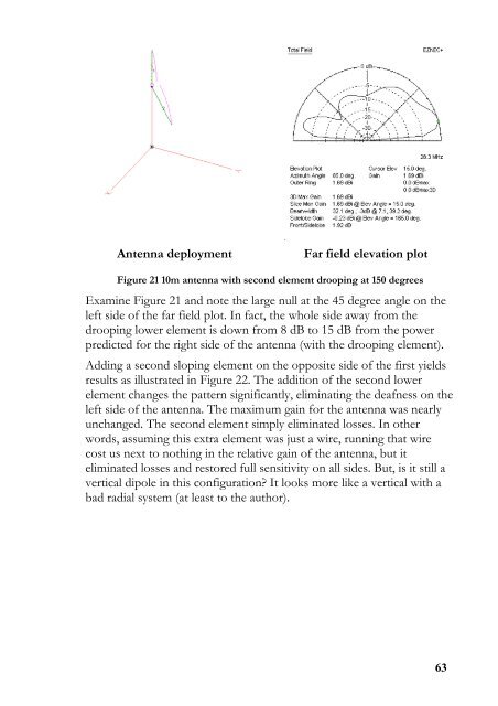
Antenna deployment<br />
Far field elevation plot<br />
Figure 21 10m antenna with second element drooping at 150 degrees<br />
Examine Figure 21 and note the large null at the 45 degree angle on the<br />
left side of the far field plot. In fact, the whole side away from the<br />
drooping lower element is down from 8 dB to 15 dB from the power<br />
predicted for the right side of the antenna (with the drooping element).<br />
Adding a second sloping element on the opposite side of the first yields<br />
results as illustrated in Figure 22. The addition of the second lower<br />
element changes the pattern significantly, eliminating the deafness on the<br />
left side of the antenna. The maximum gain for the antenna was nearly<br />
unchanged. The second element simply eliminated losses. In other<br />
words, assuming this extra element was just a wire, running that wire<br />
cost us next to nothing in the relative gain of the antenna, but it<br />
eliminated losses and restored full sensitivity on all sides. But, is it still a<br />
vertical dipole in this configuration? It looks more like a vertical with a<br />
bad radial system (at least to the author).<br />
63