Pipeline Failure Investigation Report - PHMSA - U.S. Department of ...
Pipeline Failure Investigation Report - PHMSA - U.S. Department of ...
Pipeline Failure Investigation Report - PHMSA - U.S. Department of ...

Create successful ePaper yourself
Turn your PDF publications into a flip-book with our unique Google optimized e-Paper software.
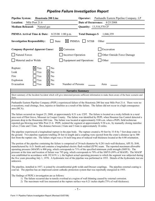
<strong>Pipeline</strong> <strong>Failure</strong> <strong>Investigation</strong> <strong>Report</strong><br />
<strong>Pipeline</strong> System: Houstonia 200 Line Operator: Panhandle Eastern <strong>Pipeline</strong> Company, LP<br />
Location: Mile Post 21.6 Date <strong>of</strong> Occurrence: 8/25/2008<br />
Medium Released: Natural gas Quantity: 13,518,578 CF<br />
<strong>PHMSA</strong> Arrival Time & Date: 8/25/08 1:00 p.m. Total Damages $ 1,046,359<br />
<strong>Investigation</strong> Responsibility: State <strong>PHMSA</strong> NTSB Other<br />
Company <strong>Report</strong>ed Apparent Cause: Corrosion Excavation<br />
Natural Forces Incorrect Operation Other Outside Force Damage<br />
Material and/or Welds Equipment and Operations Other<br />
Rupture Yes No<br />
Leak Yes No<br />
Fire Yes No<br />
Explosion Yes No<br />
Evacuation Yes No Number <strong>of</strong> Persons Area<br />
Narrative Summary<br />
Short summary <strong>of</strong> the Incident/Accident which will give interested persons sufficient information to make them aware <strong>of</strong> the basic scenario and<br />
facts.<br />
Panhandle Eastern <strong>Pipeline</strong> Company (PEPL) experienced failure <strong>of</strong> the Houstonia 200 line near Mile Post 21.6. There were no<br />
evacuations, road closings, fires, injuries or fatalities as a result <strong>of</strong> the failure. The failure did not occur in a high consequence<br />
area (HCA).<br />
The failure occurred on August 25, 2008, at approximately 8:51 a.m. CDT. The failure is located on a rocky hillside in a rural<br />
area west <strong>of</strong> Pilot Grove, Missouri in Cooper County. The failure was identified by PEPL when Houston Gas Control detected a<br />
pressure drop in the Houstonia 200 Line. The failure was located at approximately 9:00 a.m. when a PEPL field technician<br />
reported gas blowing near Mile Post 21.6. PEPL isolated the segment at approximately 9:30 a.m., by manually closing mainline<br />
valves 2 Gate and 3 Gate. The distance between 2 Gate and 3 Gate is approximately 16 miles.<br />
The pipeline experienced a longitudinal rupture in the pipe body. The rupture created a 50 feet by 33 ft by 7 feet deep crater in<br />
the ground. Two pipeline segments totalling 28 feet in length and a coupling were ejected from the crater a distance up to 300<br />
feet from the rupture site. The failure origin was a 16 inch long area <strong>of</strong> reduced wall thickness located at the 6:00 orientation.<br />
The portion <strong>of</strong> the pipeline containing the failure is comprised <strong>of</strong> 24-inch diameter by 0.281-inch wall thickness, API 5L-X48,<br />
manufactured by A.O. Smith and contains a longitudinal electric flash welded (EFW) seam. The reported maximum allowable<br />
operating pressure (MAOP) is 800 psig, which corresponds to 71% <strong>of</strong> the specified minimum yield strength (SMYS). The<br />
pressure at the time and location <strong>of</strong> failure was 795 psig, which corresponds to 70% <strong>of</strong> the SMYS (99% <strong>of</strong> MAOP). The MAOP<br />
was established in accordance with 192.619 ( c ), the highest actual operating pressure to which the segment was subjected during<br />
the five years preceding July 1, 1970. A hydrostatic test <strong>of</strong> the pipeline was performed in 1955. Details <strong>of</strong> the hydrostatic test are<br />
unknown.<br />
The pipeline, installed in 1937, is joined by circumferential girth welds and Dresser couplings. The pipeline external coating is<br />
coal tar. The pipeline has an impressed curent cathodic protection system that was reportedly energized in 1955.<br />
The findings <strong>of</strong> PEPL's investigation are as follows:<br />
1) The failure occurred due to tensile overload at a region <strong>of</strong> wall thinning caused by external corrosion.<br />
2) The maximum wall loss measured at the rupture surface was 0.21 inches depth (75% <strong>of</strong> wall thickness).<br />
- 1 -<br />
Form 11 <strong>Pipeline</strong> <strong>Failure</strong> <strong>Investigation</strong> <strong>Report</strong> (Revised 03/07/08)
<strong>Pipeline</strong> <strong>Failure</strong> <strong>Investigation</strong> <strong>Report</strong><br />
PEPL submitted a return to service plan to <strong>PHMSA</strong> that included a temporary 20% pressure reduction and remediation <strong>of</strong><br />
anomalies found in a high resoultion MFL tool run. They subsequently remediated 30 anomalies with RPR less than 1.15 and<br />
replaced 912 feet <strong>of</strong> pipe. On 12/19/2009 the temporary pressure restriction was removed.<br />
ACTIVITY #: 122653<br />
OPERATOR ID #: 15105<br />
UNIT ID #: 4093<br />
NRC REPORT #: 881717<br />
INCIDENT REPORT # (FORM 7100.2): 20090030 -- 5319<br />
Region/State __Central_______________________<br />
Principal Investigator: _Roger Sneegas________<br />
Date: _10/12/2010________________________<br />
Reviewed by: __David Barrett__original initialed_______<br />
Title: __Director – Central Region___________________<br />
Date: __10/13/2010_________________________<br />
- 2 -<br />
Form 11 <strong>Pipeline</strong> <strong>Failure</strong> <strong>Investigation</strong> <strong>Report</strong> (Revised 03/07/08)
<strong>Pipeline</strong> <strong>Failure</strong> <strong>Investigation</strong> <strong>Report</strong><br />
<strong>Failure</strong> Location & Response<br />
Location (City, Township, Range, County/Parish):<br />
Pilot Grove, Missouri<br />
Address or M.P. on <strong>Pipeline</strong>:<br />
Type <strong>of</strong> Area (Rural, City):<br />
21.6 Rural<br />
(1)<br />
(Acquire Map)<br />
(1)<br />
Date: 8/25/2008 Time <strong>of</strong> <strong>Failure</strong>: 8:51 a.m.<br />
Time Detected: 9:00 a.m.<br />
How Located:<br />
Time Located: 9:10 a.m.<br />
A technician - Jerry Miller - heard the pipeline blowing from the nearest road at about 9:00 a.m. Gas control<br />
had previously noted a pressure drop at 8:51 a.m.<br />
NRC <strong>Report</strong> #: (Attach <strong>Report</strong>) Time <strong>Report</strong>ed to NRC: <strong>Report</strong>ed by:<br />
881717 10:15 a.m. on 8/25/2008 Liz Rutherford<br />
Type <strong>of</strong> <strong>Pipeline</strong>:<br />
Gas Distribution Gas Transmission Hazardous Liquid LNG<br />
LP Interstate Gas Interstate Liquid LNG Facility<br />
Municipal Intrastate Gas Intrastate Liquid<br />
Public Utility Jurisdictional Gas Gathering Offshore Liquid<br />
Master Meter Offshore Gas Jurisdictional Liquid Gathering<br />
Offshore Gas - High H 2 S CO 2<br />
<strong>Pipeline</strong> Configuration (Regulator Station, Pump Station, <strong>Pipeline</strong>, etc.):<br />
Mainline Houstonia 200<br />
Owner: Panhandle Eastern <strong>Pipeline</strong><br />
Address:<br />
5444 Westheimer Road<br />
Houston TX<br />
Operator/Owner Information<br />
Operator: Panhandle Eastern <strong>Pipeline</strong><br />
Address:<br />
5444 Westheimer Road<br />
Houston TX<br />
Company Official: Eric Amundsen<br />
Company Official: Eric Amundsen<br />
Phone No.: 713-989-7460 Fax No.: Phone No. 713-989-7460 Fax No.<br />
Drug and Alcohol Testing Program Contacts<br />
Drug Program Contact & Phone: Brett Laaser<br />
Alcohol Program Contact & Phone: 713-989-7549<br />
N/A<br />
Damages<br />
Product/Gas Loss or Spill (2) 13,518,578 CF Estimated Property Damage $ 25,000<br />
Amount Recovered 0 Associated Damages (3) $ 628,063<br />
1 Photo documentation<br />
2 Initial volume lost or spilled<br />
3 Including cleanup cost<br />
- 3 -<br />
Form 11 <strong>Pipeline</strong> <strong>Failure</strong> <strong>Investigation</strong> <strong>Report</strong> (Revised 03/07/08)
Estimated Amount $ 393,296<br />
<strong>Pipeline</strong> <strong>Failure</strong> <strong>Investigation</strong> <strong>Report</strong><br />
Damages<br />
Description <strong>of</strong> Property Damage:<br />
The failure caused a crater in the right-<strong>of</strong>-way measuring about 50 X 33 feet and 7 feet deep. Two segments <strong>of</strong> pipe (46 feet<br />
total) were ejected from the crater.<br />
Customers out <strong>of</strong> Service: Yes No Number:<br />
Suppliers out <strong>of</strong> Service: Yes No Number:<br />
Fatalities and Injuries<br />
Fatalities: Yes No Company: Contractor: Public:<br />
Injuries - Hospitalization: Yes No Company: Contractor: Public:<br />
Injuries - Non-Hospitalization: Yes No Company: Contractor: Public:<br />
Total Injuries (including Non-Hospitalization): Company: Contractor: Public:<br />
Yrs w/ Yrs.<br />
Name Job Function Comp. Exp.<br />
Type <strong>of</strong> Injury<br />
Drug/Alcohol Testing<br />
N/A<br />
Were all employees that could have contributed to the incident, post-accident tested within the 2 hour time frame for alcohol or<br />
the 32 hour time frame for all other drugs?<br />
Yes No<br />
Job Function Test Date & Time Location<br />
Results<br />
Pos Neg<br />
Type <strong>of</strong> Drug<br />
Gas System Controller 8/25/2008 Houston TX<br />
- 4 -<br />
Form 11 <strong>Pipeline</strong> <strong>Failure</strong> <strong>Investigation</strong> <strong>Report</strong> (Revised 03/07/08)
<strong>Pipeline</strong> <strong>Failure</strong> <strong>Investigation</strong> <strong>Report</strong><br />
System Description<br />
Describe the Operator's System:<br />
The Houstonia 200 line runs from Liberal KS to Howell MI. It is 24-inch diameter 0.281-inch wall X48 pipe installed in 1937.<br />
Pipe <strong>Failure</strong> Description<br />
Length <strong>of</strong> <strong>Failure</strong> (inches, feet, miles): 46 feet<br />
Position (Top, Bottom, include position on pipe, 6 O'clock): (1) Description <strong>of</strong> <strong>Failure</strong> (Corrosion Gouge, Seam Split):<br />
Bottom 6 O'clock<br />
External corrosion.<br />
N/A<br />
(1)<br />
(1)<br />
Laboratory Analysis: Yes No<br />
Performed by: CC Technologies Inc.<br />
Preservation <strong>of</strong> Failed Section or Component: Yes No<br />
If Yes - Method: Wrapped<br />
In Custody <strong>of</strong>: Panhandle<br />
Develop a sketch <strong>of</strong> the area including distances from roads, houses, stress inducing factors, pipe configurations, etc. Bar Hole<br />
Test Survey Plot should be outlined with concentrations at test points. Direction <strong>of</strong> Flow.<br />
Component Failed:<br />
Manufacturer:<br />
Pressure Rating:<br />
Other (Breakout Tank, Underground Storage):<br />
Component <strong>Failure</strong> Description<br />
Model:<br />
Size<br />
N/A<br />
(1)<br />
Pipe Data<br />
Material: steel<br />
Wall Thickness/SDR: 0.281- inch<br />
Diameter (O.D.): 24-inch Installation Date: 1937<br />
SMYS: 48,000<br />
Manufacturer: A. O. Smith<br />
Longitudinal Seam: Electric Flash Weld<br />
Type <strong>of</strong> Coating: Coal Tar<br />
Pipe Specifications (API 5L, ASTM A53, etc.): API 5L, X48<br />
Joining<br />
Type: Girth weld with Coupling every other joint<br />
Procedure:<br />
NDT Method: Unknown Inspected: Yes No<br />
N/A<br />
N/A<br />
- 5 -<br />
Form 11 <strong>Pipeline</strong> <strong>Failure</strong> <strong>Investigation</strong> <strong>Report</strong> (Revised 03/07/08)
<strong>Pipeline</strong> <strong>Failure</strong> <strong>Investigation</strong> <strong>Report</strong><br />
Pressure @ Time <strong>of</strong> <strong>Failure</strong> @ <strong>Failure</strong> Site<br />
N/A<br />
Pressure @ <strong>Failure</strong> Site: 795 psig at the Houstonia Station Elevation @ <strong>Failure</strong> Site: 660<br />
Pressure Readings @ Various Locations:<br />
Direction from <strong>Failure</strong> Site<br />
Location/M.P./Station # Pressure (psig) Elevation (ft msl) Upstream Downstream<br />
N/A<br />
Type <strong>of</strong> Product:<br />
Specific Gravity:<br />
Pressure @ Time <strong>of</strong> <strong>Failure</strong> (4)<br />
High Pressure Set Point:<br />
Specific Gravity: .55<br />
Pressure @ Time <strong>of</strong> <strong>Failure</strong> (4) 795 psig<br />
High Pressure Set Point: 830 psig<br />
Upstream Pump Station Data<br />
API Gravity:<br />
Flow Rate:<br />
Distance to <strong>Failure</strong> Site:<br />
Low Pressure Set Point:<br />
Upstream Compressor Station Data<br />
Flow Rate:<br />
Distance to <strong>Failure</strong> Site: 21.6 miles<br />
Low Pressure Set Point:<br />
N/A<br />
N/A<br />
Operating Pressure<br />
Max. Allowable Operating Pressure: 800 psig<br />
Determination <strong>of</strong> MAOP: 192.619 (c)<br />
Actual Operating Pressure: 795 psig<br />
Method <strong>of</strong> Over Pressure Protection: Engine safeties - first engine speed and torque, then shutdown.<br />
Relief Valve Set Point: 830 psig Capacity Adequate? Yes No<br />
Integrity Test After <strong>Failure</strong><br />
Pressure Test Conducted in place? (Conducted on Failed Components or Associated Piping): Yes No<br />
If NO, Tested after removal? Yes No<br />
Method: N/A<br />
Describe any failures during the test.<br />
N/A<br />
N/A<br />
Soil/water Conditions @ <strong>Failure</strong> Site<br />
Condition <strong>of</strong> and Type <strong>of</strong> Soil around <strong>Failure</strong> Site (Color, Wet, Dry, Frost Depth): Dry and very rocky<br />
N/A<br />
Type <strong>of</strong> Backfill (Size and Description): Rock<br />
4 Obtain event logs and pressure recording charts<br />
- 6 -<br />
Form 11 <strong>Pipeline</strong> <strong>Failure</strong> <strong>Investigation</strong> <strong>Report</strong> (Revised 03/07/08)
<strong>Pipeline</strong> <strong>Failure</strong> <strong>Investigation</strong> <strong>Report</strong><br />
Soil/water Conditions @ <strong>Failure</strong> Site<br />
Type <strong>of</strong> Water (Salt, Brackish): N/A Water Analysis (5) Yes No<br />
N/A<br />
External Pipe or Component Examination<br />
(1)<br />
External Corrosion? Yes No<br />
Coating Condition (Disbonded, Non-existent):<br />
Coal tar - some disbonded<br />
Description <strong>of</strong> Corrosion:<br />
The failed pipeline segments showed multiple areas <strong>of</strong> external corrosion with reduced wall thickness.<br />
N/A<br />
(1)<br />
Description <strong>of</strong> <strong>Failure</strong> Surface (Gouges, Arc Burns, Wrinkle Bends, Cracks, Stress Cracks, Chevrons, Fracture Mode, Point <strong>of</strong><br />
Origin):<br />
A 23 foot section <strong>of</strong> pipe was ejected and completely ruptured by the failure. Chevrons along the rupture pointed toward the<br />
origin in an area <strong>of</strong> external corrosion with reduced wall thickness.<br />
Above Ground: Yes No<br />
Stress Inducing Factors:<br />
(1)<br />
(1)<br />
Buried: Yes No<br />
Depth <strong>of</strong> Cover: 6 feet<br />
(1)<br />
(1)<br />
Cathodic Protection<br />
P/S (Surface): Readings taken this Spring were adequate - > .85 P/S (Interface): Not taken<br />
V - Recent reading in the area -2.1 V 3/26/08<br />
Soil Resistivity: No soil - rock pH: Date <strong>of</strong> Installation: 1955<br />
Method <strong>of</strong> Protection: Rectifiers<br />
N/A<br />
Did the Operator have knowledge <strong>of</strong> Corrosion before the Incident? Yes No<br />
How Discovered? (Close Interval Survey, Instrumented Pig, Annual Survey, Rectifier Readings, ECDA, etc): A close interval<br />
survey was performed in 2000 from 2 Gate to 3 Gate. Some areas <strong>of</strong> low pipe to soil potential were found but not in the<br />
area <strong>of</strong> the failure. See Appendix D.<br />
Internal Corrosion: Yes No<br />
Internal Pipe or Component Examination<br />
(1)<br />
Injected Inhibitors: Yes No<br />
Type <strong>of</strong> Inhibitors: N/A Testing: Yes No<br />
N/A<br />
Results (Coupon Test, Corrosion Resistance Probe): N/A<br />
Description <strong>of</strong> <strong>Failure</strong> Surface (MIC, Pitting, Wall Thinning, Chevrons, Fracture Mode, Point <strong>of</strong> Origin):<br />
The cause <strong>of</strong> the failure was external corrosion with reduced wall thickness.<br />
Cleaning Pig Program: Yes No Gas and/or Liquid Analysis: Yes No<br />
5 Attach copy <strong>of</strong> water analysis report<br />
- 7 -<br />
Form 11 <strong>Pipeline</strong> <strong>Failure</strong> <strong>Investigation</strong> <strong>Report</strong> (Revised 03/07/08)
<strong>Pipeline</strong> <strong>Failure</strong> <strong>Investigation</strong> <strong>Report</strong><br />
Internal Pipe or Component Examination<br />
Results <strong>of</strong> Gas and/or Liquid Analysis (6) N/A<br />
N/A<br />
Internal Inspection Survey: Yes No Results (7) ILI had been scheduled but not done.<br />
Did the Operator have knowledge <strong>of</strong> Corrosion before the Incident? Yes No<br />
How Discovered? (Instrumented Pig, Coupon Testing, ICDA, etc.): N/A<br />
Responsible Party:<br />
Address:<br />
Work Being Performed:<br />
Outside Force Damage<br />
Telephone No.:<br />
N/A<br />
Equipment Involved:<br />
(1)<br />
Called One Call System? Yes No<br />
One Call Name: One Call <strong>Report</strong> # (8)<br />
Notice Date:<br />
Time:<br />
Response Date:<br />
Time:<br />
Details <strong>of</strong> Response:<br />
Was Location Marked According to Procedures? Yes No<br />
<strong>Pipeline</strong> Marking Type:<br />
(1)<br />
Location:<br />
(1)<br />
State Law Damage Prevention Program Followed? Yes No No State Law<br />
Notice Required: Yes No Response Required: Yes No<br />
Was Operator Member <strong>of</strong> State One Call? Yes No Was Operator on Site? Yes No<br />
Did a deficiency in the Public Awareness Program contribute to the accident? Yes No<br />
Is OSHA Notification Required? Yes No<br />
6 Attach copy <strong>of</strong> gas and/or liquid analysis report<br />
7 Attach copy <strong>of</strong> internal inspection survey report<br />
8 Attach copy <strong>of</strong> one-call report<br />
- 8 -<br />
Form 11 <strong>Pipeline</strong> <strong>Failure</strong> <strong>Investigation</strong> <strong>Report</strong> (Revised 03/07/08)
<strong>Pipeline</strong> <strong>Failure</strong> <strong>Investigation</strong> <strong>Report</strong><br />
Description (Earthquake, Tornado, Flooding, Erosion):<br />
Natural Forces<br />
N/A<br />
<strong>Failure</strong> Isolation<br />
Squeeze Off/Stopple Location and Method:<br />
Panhandle isolated the failure by manually closing 2 Gate and 3 Gate.<br />
N/A<br />
(1)<br />
Valve Closed - Upstream: 2 Gate<br />
I.D.:<br />
Time: 9:38 AM M.P.: 12.97<br />
Valve Closed - Downstream: 3 Gate<br />
I.D.:<br />
Time: 9:23 M.P.: 28.43<br />
<strong>Pipeline</strong> Shutdown Method: Manual Automatic SCADA Controller ESD<br />
Failed Section Bypassed or Isolated: Isolated<br />
Performed By: Field Tech.<br />
Valve Spacing: 16 miles<br />
Odorization<br />
Gas Odorized: Yes No Concentration <strong>of</strong> Odorant (Post Incident at <strong>Failure</strong> Site):<br />
N/A<br />
Method <strong>of</strong> Determination: Yes No % LEL: Yes No % Gas In Air: Yes No<br />
Was Odorizer Working Prior to the Incident?<br />
Yes No<br />
Odorant Manufacturer:<br />
Model:<br />
Amount Injected:<br />
Time Taken: Yes No<br />
Type <strong>of</strong> Odorizer (Wick, By-Pass):<br />
Type <strong>of</strong> Odorant:<br />
Monitoring Interval (Weekly):<br />
Odorization History (Leaks Complaints, Low Odorant Levels, Monitoring Locations, Distances from <strong>Failure</strong> Site):<br />
- 9 -<br />
Form 11 <strong>Pipeline</strong> <strong>Failure</strong> <strong>Investigation</strong> <strong>Report</strong> (Revised 03/07/08)
<strong>Pipeline</strong> <strong>Failure</strong> <strong>Investigation</strong> <strong>Report</strong><br />
Odorization<br />
N/A<br />
Temperature: 85 F<br />
Climate (Snow, Rain): Sunny<br />
Weather Conditions<br />
Wind (Direction & Speed): light<br />
Humidity:<br />
N/A<br />
Was Incident preceded by a rapid weather change? Yes No<br />
Weather Conditions Prior to Incident (Cloud Cover, Ceiling Heights, Snow, Rain, Fog):<br />
Clear<br />
Gas Migration Survey<br />
N/A<br />
Bar Hole Test <strong>of</strong> Area: Yes No Equipment Used:<br />
Method <strong>of</strong> Survey (Foundations, Curbs, Manholes, Driveways, Mains, Services)<br />
(9) (1)<br />
Environment Sensitivity Impact<br />
Location (Nearest Rivers, Body <strong>of</strong> Water, Marshlands, Wildlife Refuge, City Water Supplies that could be or were affected<br />
by the medium loss):<br />
N/A<br />
(1)<br />
OPA Contingency Plan Available? Yes No Followed? Yes No<br />
Class Location: 1 2 3 4<br />
Determination:<br />
Odorization Required? Yes No N/A<br />
Class Location/High Consequence Area<br />
Pressure Test History<br />
(Expand List as Necessary)<br />
HCA Area? Yes No N/A<br />
Determination:<br />
N/A<br />
N/A<br />
9 Plot on site description page<br />
- 10 -<br />
Form 11 <strong>Pipeline</strong> <strong>Failure</strong> <strong>Investigation</strong> <strong>Report</strong> (Revised 03/07/08)
<strong>Pipeline</strong> <strong>Failure</strong> <strong>Investigation</strong> <strong>Report</strong><br />
Pressure Test History<br />
(Expand List as Necessary)<br />
N/A<br />
Installation<br />
Req’d (10) Assessment<br />
Deadline Date<br />
N/A<br />
Test Date<br />
Test Medium<br />
Pressure<br />
(psig)<br />
Duration<br />
(hrs)<br />
% SMYS<br />
Next N/A 1955 Water Unknown Unknown Unknown<br />
Next<br />
Most Recent<br />
Describe any problems experienced during the pressure tests.<br />
Hydrostatic test done in 1955 - details unknown.<br />
Internal Line Inspection/Other Assessment History<br />
(Expand List as Necessary)<br />
N/A<br />
Req’d (10) Assessment<br />
Deadline Date<br />
Assessment<br />
Date<br />
Type <strong>of</strong> ILI<br />
Tool (11)<br />
Other Assessment<br />
Method (12)<br />
Indicated Anomaly<br />
If yes, describe below<br />
Initial 2012 Yes No<br />
Next Yes No<br />
Next Yes No<br />
Most Recent Yes No<br />
Describe any previously indicated anomalies at the failed pipe, and any subsequent pipe inspections (anomaly digs) and remedial<br />
actions.<br />
Not scheduled until 2012. Not in top 50%. Gauge tool run already.<br />
Pre-<strong>Failure</strong> Conditions and Actions<br />
N/A<br />
Was there a known pre-failure condition requiring (10) the operator to schedule evaluation and remediation?<br />
Yes (describe below or on attachment) No<br />
If there was such a known pre-failure condition, had the operator established and adhered to a required (10) evaluation and<br />
remediation schedule? Describe below or on attachment. Yes No N/A<br />
Prior to the failure, had the operator performed the required (10) actions to address the threats that are now known to be related to<br />
the cause <strong>of</strong> this failure? Yes No N/A<br />
List below or on an attachment such operator-identified threats, and operator actions taken prior to the accident.<br />
Describe any previously indicated anomalies at the failed pipe, and any subsequent pipe inspections (anomaly digs) and remedial<br />
actions.<br />
N/A<br />
Maps & Records<br />
N/A<br />
10 As required <strong>of</strong> <strong>Pipeline</strong> Integrity Management regulations in 49CFR Parts 192 and 195<br />
11 MFL, geometry, crack, etc.<br />
12 ECDA, ICDA, SCCDA, “other technology,” etc.<br />
- 11 -<br />
Form 11 <strong>Pipeline</strong> <strong>Failure</strong> <strong>Investigation</strong> <strong>Report</strong> (Revised 03/07/08)
<strong>Pipeline</strong> <strong>Failure</strong> <strong>Investigation</strong> <strong>Report</strong><br />
Are Maps and Records Current? (13) Yes No<br />
Comments:<br />
Leak Survey History<br />
Leak Survey History (Trend Analysis, Leak Plots):<br />
Leak survey on 6/25/2007. No leaks were found in the area <strong>of</strong> the failure.<br />
N/A<br />
Description (Repair or Leak <strong>Report</strong>s, Exposed Pipe <strong>Report</strong>s):<br />
N/A<br />
<strong>Pipeline</strong> Operation History<br />
N/A<br />
Did a Safety Related Condition Exist Prior to <strong>Failure</strong>? Yes No <strong>Report</strong>ed? Yes No<br />
Unaccounted For Gas: None before the incident.<br />
Over & Short/Line Balance (24 hr., Weekly, Monthly/Trend):<br />
Name:<br />
Title:<br />
Training (Type <strong>of</strong> Training, Background):<br />
Operator/Contractor Error<br />
Job Function:<br />
Years <strong>of</strong> Experience:<br />
N/A<br />
Was the person “Operator Qualified” as applicable to a precursor abnormal operating condition? Yes No N/A<br />
Was qualified individual suspended from performing covered task Yes No N/A<br />
Type <strong>of</strong> Error (Inadvertent Operation <strong>of</strong> a Valve):<br />
Procedures that are required:<br />
Actions that were taken:<br />
Pre-Job Meeting (Construction, Maintenance, Blow Down, Purging, Isolation):<br />
Prevention <strong>of</strong> Accidental Ignition (Tag & Lock Out, Hot Weld Permit):<br />
Procedures conducted for Accidental Ignition:<br />
Was a Company Inspector on the Job? Yes No<br />
Was an Inspection conducted on this portion <strong>of</strong> the job? Yes No<br />
13 Obtain copies <strong>of</strong> maps and records<br />
- 12 -<br />
Form 11 <strong>Pipeline</strong> <strong>Failure</strong> <strong>Investigation</strong> <strong>Report</strong> (Revised 03/07/08)
<strong>Pipeline</strong> <strong>Failure</strong> <strong>Investigation</strong> <strong>Report</strong><br />
Operator/Contractor Error<br />
Additional Actions (Contributing factors may include number <strong>of</strong> hours at work prior to failure or time <strong>of</strong> day work being<br />
conducted):<br />
N/A<br />
Training Procedures:<br />
Operation Procedures:<br />
Controller Activities:<br />
Name<br />
Title<br />
Years<br />
Experience<br />
Hours on Duty<br />
Prior to <strong>Failure</strong><br />
Shift<br />
Alarm Parameters:<br />
High/Low Pressure Shutdown:<br />
Flow Rate:<br />
Procedures for Clearing Alarms:<br />
Type <strong>of</strong> Alarm:<br />
Company Response Procedures for Abnormal Operations:<br />
Over/Short Line Balance Procedures:<br />
Frequency <strong>of</strong> Over/Short Line Balance:<br />
Additional Actions:<br />
Additional Actions Taken by the Operator<br />
N/A<br />
Make notes regarding the emergency and <strong>Failure</strong> <strong>Investigation</strong> Procedures (Pressure reduction, Reinforced Squeeze Off, Clean<br />
Up, Use <strong>of</strong> Evacuators, Line Purging, closing Additional Valves, Double Block and Bleed, Continue Operating downstream<br />
Pumps):<br />
- 13 -<br />
Form 11 <strong>Pipeline</strong> <strong>Failure</strong> <strong>Investigation</strong> <strong>Report</strong> (Revised 03/07/08)
<strong>Pipeline</strong> <strong>Failure</strong> <strong>Investigation</strong> <strong>Report</strong><br />
Additional Actions Taken by the Operator<br />
N/A<br />
The failure was detected by Gas Control in Houston at 8:51 a.m. on 8/25/2008. Field crews located the failure at 9:10<br />
a.m. The failure was isolated by closing valves at about 9:30 a.m.<br />
Panhandle sent a team to investigate the failure on 8/26/08. After the initial investigation, the pipeline was repaired and<br />
returned to service at 80% <strong>of</strong> the pressure at the time <strong>of</strong> the incident (795 psi) pending the results <strong>of</strong> the investigation.<br />
- 14 -<br />
Form 11 <strong>Pipeline</strong> <strong>Failure</strong> <strong>Investigation</strong> <strong>Report</strong> (Revised 03/07/08)
<strong>Pipeline</strong> <strong>Failure</strong> <strong>Investigation</strong> <strong>Report</strong><br />
Photo Documentation (1)<br />
Overall Area from best possible view. Pictures from the four points <strong>of</strong> the compass. Failed Component, Operator Action, Damages in Area,<br />
Address Markings, etc.<br />
Photo<br />
No.<br />
Description<br />
Roll<br />
No.<br />
- 15 -<br />
Photo<br />
No.<br />
1 View looking west at the crater 1<br />
2 East view <strong>of</strong> exposed pipe in crater 2<br />
3 West view <strong>of</strong> exposed pipe in crater 3<br />
4 View <strong>of</strong> longer ejected pipe segment 4<br />
5 Close view <strong>of</strong> longer segment 5<br />
6 View <strong>of</strong> shorter ejected segment 6<br />
7 Another view <strong>of</strong> shorter segment 7<br />
8 Possible failure origin on shorter segment 8<br />
9 Side view <strong>of</strong> possible failure. 9<br />
10 View <strong>of</strong> coupling ejected into the woods 10<br />
11<br />
12<br />
13<br />
Close up <strong>of</strong> corrosion at possible failure<br />
origin.<br />
View <strong>of</strong> another area <strong>of</strong> external corrosion<br />
near the failure origin<br />
View <strong>of</strong> failure origin after the pipe was<br />
moved.<br />
14 14<br />
15 15<br />
16 16<br />
17 17<br />
18 18<br />
19 19<br />
20 20<br />
21 21<br />
22 22<br />
23 23<br />
24 24<br />
25 25<br />
26 26<br />
27 27<br />
28 28<br />
29 29<br />
30 30<br />
Type <strong>of</strong> Camera:<br />
11<br />
12<br />
13<br />
Description<br />
Roll<br />
No.<br />
Form 11 <strong>Pipeline</strong> <strong>Failure</strong> <strong>Investigation</strong> <strong>Report</strong> (Revised 03/07/08)
<strong>Pipeline</strong> <strong>Failure</strong> <strong>Investigation</strong> <strong>Report</strong><br />
Film ASA:<br />
Photo Documentation (1)<br />
Video Counter Log (Attach Copy):<br />
Police:<br />
Fire Dept.:<br />
Additional Information Sources<br />
Agency Name Title Phone Number<br />
State Fire Marshall:<br />
State Agency:<br />
NTSB:<br />
EPA:<br />
FBI:<br />
ATF:<br />
OSHA:<br />
Insurance Co.:<br />
FRA:<br />
MMS:<br />
Television:<br />
Newspaper:<br />
Other:<br />
Cooper County Sheriff<br />
Pilot Grove Fire Dept<br />
Missouri DOT Emergency<br />
Response Team<br />
No<br />
- 16 -<br />
Form 11 <strong>Pipeline</strong> <strong>Failure</strong> <strong>Investigation</strong> <strong>Report</strong> (Revised 03/07/08)
<strong>Pipeline</strong> <strong>Failure</strong> <strong>Investigation</strong> <strong>Report</strong><br />
Persons Interviewed<br />
Name Title Phone Number<br />
Brad Howard Operations Specialist 660-568-1221<br />
Mike Dawson<br />
Steve Atkinson Technical Specialist 913-906-1522<br />
Jerry Rau Director <strong>Pipeline</strong> Integrity 713-989-7417<br />
Rob Wesch<br />
Liz Rutherford<br />
Brian Kraft<br />
Measurement Tech<br />
Dan Corpening<br />
Area Director<br />
Ross Cummins<br />
CP Tech<br />
Richard Gifford<br />
Corrosion Tech<br />
Gerald Moore<br />
Environmental Coordinator<br />
- 17 -<br />
Form 11 <strong>Pipeline</strong> <strong>Failure</strong> <strong>Investigation</strong> <strong>Report</strong> (Revised 03/07/08)
<strong>Pipeline</strong> <strong>Failure</strong> <strong>Investigation</strong> <strong>Report</strong><br />
Event Log<br />
Sequence <strong>of</strong> events prior, during, and after the incident by time. (Consider the events <strong>of</strong> all parties involved in the incident, Fire <strong>Department</strong> and<br />
Police reports, Operator Logs and other government agencies.)<br />
Time<br />
8:51 a.m. 8/25/08 Gas Control detects a pressure drop on the Houstonia 200 line and asks field techs to check for a leak.<br />
9:00 a.m. Filed techs hear blowing gas near mile post 21.6<br />
9:10 a.m. Field techs locate the failure<br />
9:23 a.m. 3 Gate at MP 28.43 is closed manually<br />
9:38 a.m. 2 Gate at MP 12.97 is closed manually<br />
Event<br />
9:00 -11:00 a.m. Panhandle, Fire and police check the area to see if evacuations are necessary<br />
1:00 p.m. <strong>PHMSA</strong> investigator arrives on site.<br />
1:00 - 8:00 p.m. <strong>Investigation</strong> by <strong>PHMSA</strong> and Panhandle<br />
12:00 p.m. 8/26 Panhandle investigation team from Houston arrives<br />
12:00 - 7:00 p.m. <strong>Investigation</strong> <strong>of</strong> the failure site by <strong>PHMSA</strong> and Panhandle.<br />
- 18 -<br />
Form 11 <strong>Pipeline</strong> <strong>Failure</strong> <strong>Investigation</strong> <strong>Report</strong> (Revised 03/07/08)
<strong>Pipeline</strong> <strong>Failure</strong> <strong>Investigation</strong> <strong>Report</strong><br />
<strong>Investigation</strong> Contact Log<br />
Time Date Name Description<br />
1:00 8/26/08 Brad Howard Operations Specialist<br />
p.m.<br />
1:30 8/26/08 Steve Atkinson Technical Specialist<br />
p.m.<br />
12:00 8/27/08 Jerry Rau Director <strong>Pipeline</strong> Integrity<br />
p.m.<br />
1:00 8/26- Brad Howard<br />
Follow up on various issues<br />
p.m. 10/20<br />
10:00 9/26/08 David McQuilling Principal Engineer - conference call on cathodic protection<br />
a.m.<br />
10:00<br />
a.m.<br />
9/26/08 Steve Atkinson Same conference call.<br />
- 19 -<br />
Form 11 <strong>Pipeline</strong> <strong>Failure</strong> <strong>Investigation</strong> <strong>Report</strong> (Revised 03/07/08)
<strong>Pipeline</strong> <strong>Failure</strong> <strong>Investigation</strong> <strong>Report</strong><br />
<strong>Failure</strong> <strong>Investigation</strong> Documentation Log<br />
Operator: Unit #: CPF #: Date:<br />
Appendix<br />
Date FOIA<br />
Documentation Description<br />
Number Received Yes No<br />
A <strong>Investigation</strong> Pictures 8/25/08 X<br />
B Panhandle Incident <strong>Report</strong> 9/18/08 X<br />
C Panhandle Laboratory <strong>Failure</strong> Analysis 10/29/08 X<br />
D Panhandle Close Interval Survey 9/18/08 X<br />
- 20 -<br />
Form 11 <strong>Pipeline</strong> <strong>Failure</strong> <strong>Investigation</strong> <strong>Report</strong> (Revised 03/07/08)
<strong>Pipeline</strong> <strong>Failure</strong> <strong>Investigation</strong> <strong>Report</strong><br />
Site Description<br />
Provide a sketch <strong>of</strong> the area including distances from roads, houses, stress inducing factors, pipe configurations, etc. Bar Hole Test Survey Plot<br />
should be outlined with concentrations at test points. Photos should be taken from all angles with each photo documented. Additional areas<br />
may be needed in any area <strong>of</strong> this guideline.<br />
The <strong>Failure</strong> location was about two miles northwest <strong>of</strong> Pilot Grove (Cooper County) Missouri near Highway HH.<br />
The location was near milepost 21.6 on the Houstonia 200 line on a rocky hillside in a rural area. No structures were close to the<br />
failure location. The following page shows a sketch <strong>of</strong> the location provided by Panhandle. The image below shows the Panhandle<br />
system map.<br />
Panhandle Eastern Pipe Line Company, LP<br />
Panhandle Eastern Pipe Line Company operates a 6,500-mile<br />
pipeline system with access to diverse supply sources and can<br />
deliver 2.8 Bcf/d <strong>of</strong> natural gas to Midwest and East Coast<br />
markets. Tie-ins to Chicago, Dayton and Cincinnati have added<br />
to a Midwest customer base that includes some <strong>of</strong> the nation's<br />
largest utility and industrial natural gas users. We lead the way<br />
in <strong>of</strong>fering competitive rates and a constantly evolving array <strong>of</strong><br />
customer-friendly service options.<br />
Panhandle Eastern provides:<br />
<br />
<br />
Access to diverse Midcontinent and Canadian supply<br />
sources and to major Midwest and Northeast markets.<br />
Access to 74 Bcf <strong>of</strong> storage facilities.<br />
To request a receipt and delivery point map, please<br />
contact Customer Service at 1-800-275-7375.<br />
- 21 -<br />
Form 11 <strong>Pipeline</strong> <strong>Failure</strong> <strong>Investigation</strong> <strong>Report</strong> (Revised 03/07/08)
<strong>Pipeline</strong> <strong>Failure</strong> <strong>Investigation</strong> <strong>Report</strong><br />
- 22 -<br />
Form 11 <strong>Pipeline</strong> <strong>Failure</strong> <strong>Investigation</strong> <strong>Report</strong> (Revised 03/07/08)
<strong>Pipeline</strong> <strong>Failure</strong> <strong>Investigation</strong> <strong>Report</strong><br />
Appendix A<br />
Houstonia 200 failure Pictures – 8/25/08 near Pilot Grove MO.<br />
- 23 -<br />
Form 11 <strong>Pipeline</strong> <strong>Failure</strong> <strong>Investigation</strong> <strong>Report</strong> (Revised 03/07/08)
<strong>Pipeline</strong> <strong>Failure</strong> <strong>Investigation</strong> <strong>Report</strong><br />
8/25/08 – #1- views looking West at the crater caused by the Houstonia 200 failure.<br />
- 24 -<br />
Form 11 <strong>Pipeline</strong> <strong>Failure</strong> <strong>Investigation</strong> <strong>Report</strong> (Revised 03/07/08)
<strong>Pipeline</strong> <strong>Failure</strong> <strong>Investigation</strong> <strong>Report</strong><br />
8/25/08 #2 - East view <strong>of</strong> the exposed pipe.<br />
8/25/08 #3 -West close up.<br />
- 25 -<br />
Form 11 <strong>Pipeline</strong> <strong>Failure</strong> <strong>Investigation</strong> <strong>Report</strong> (Revised 03/07/08)
<strong>Pipeline</strong> <strong>Failure</strong> <strong>Investigation</strong> <strong>Report</strong><br />
8/25/08 #4 - One <strong>of</strong> two pipe sections ejected – the longer one – about 30 feet.<br />
8/25/08 #5 -Closer view <strong>of</strong> the longer ejected section.<br />
- 26 -<br />
Form 11 <strong>Pipeline</strong> <strong>Failure</strong> <strong>Investigation</strong> <strong>Report</strong> (Revised 03/07/08)
<strong>Pipeline</strong> <strong>Failure</strong> <strong>Investigation</strong> <strong>Report</strong><br />
8/25/08 #6 -View <strong>of</strong> the shorter section ejected – about 23 feet – ruptured full length.<br />
8/25/08 #7 -Another view <strong>of</strong> same looking north.<br />
- 27 -<br />
Form 11 <strong>Pipeline</strong> <strong>Failure</strong> <strong>Investigation</strong> <strong>Report</strong> (Revised 03/07/08)
<strong>Pipeline</strong> <strong>Failure</strong> <strong>Investigation</strong> <strong>Report</strong><br />
#8 - Areas with external corrosion and reduced wall thickness – possible failure origin.<br />
8/25/08 #9 -Side view <strong>of</strong> the failure origin site with reduced wall thickness.<br />
- 28 -<br />
Form 11 <strong>Pipeline</strong> <strong>Failure</strong> <strong>Investigation</strong> <strong>Report</strong> (Revised 03/07/08)
<strong>Pipeline</strong> <strong>Failure</strong> <strong>Investigation</strong> <strong>Report</strong><br />
8/25/08 #10 -View <strong>of</strong> coupling ejected from pipeline.<br />
8/25/08 #11 -Close up <strong>of</strong> external corrosion on the possible origin site.<br />
Form 11 <strong>Pipeline</strong> <strong>Failure</strong> <strong>Investigation</strong> <strong>Report</strong> (Revised 03/07/08)<br />
- 29 -
<strong>Pipeline</strong> <strong>Failure</strong> <strong>Investigation</strong> <strong>Report</strong><br />
8/25/08 #12 - Another area <strong>of</strong> external corrosion on the shorter section near the possible failure.<br />
8/26/08 #13 -Different view <strong>of</strong> the possible failure origin after the pipe was turned over.<br />
- 30 -<br />
Form 11 <strong>Pipeline</strong> <strong>Failure</strong> <strong>Investigation</strong> <strong>Report</strong> (Revised 03/07/08)
<strong>Pipeline</strong> <strong>Failure</strong> <strong>Investigation</strong> <strong>Report</strong><br />
Appendix B<br />
Panhandle Incident <strong>Report</strong><br />
- 31 -<br />
Form 11 <strong>Pipeline</strong> <strong>Failure</strong> <strong>Investigation</strong> <strong>Report</strong> (Revised 03/07/08)
NOTICE: This report is required by 49 CFR Part 191. <strong>Failure</strong> to report can result in a civil penalty not to exceed $25,000 for each violation Form Approved<br />
for each day that such violation persists except that the maximum civil penalty shall not exceed $500,000 as provided in 49 USC 1678. OMB No. 2137-0522<br />
U.S. <strong>Department</strong> <strong>of</strong> Transportation<br />
Research and Special Programs<br />
Administration<br />
INCIDENT REPORT - GAS TRANSMISSION AND<br />
GATHERING SYSTEMS<br />
<strong>Report</strong> Date<br />
No.<br />
(DOT Use Only)<br />
INSTRUCTIONS<br />
Important: Please read the separate instructions for completing this form before you begin. They clarify the<br />
information requested and provide specific examples. If you do not have a copy <strong>of</strong> the instructions, you<br />
can obtain one from the Office Of <strong>Pipeline</strong> Safety Web Page at http://ops.dot.gov .<br />
PART A – GENERAL REPORT INFORMATION<br />
Operator Name and Address<br />
Original <strong>Report</strong> Supplemental <strong>Report</strong> Final <strong>Report</strong><br />
a. Operator's 5-digit Identification Number (when known) / /<br />
b. If Operator does not own the pipeline, enter Owner’s 5-digit Identification Number (when known) / /<br />
c. Name <strong>of</strong> Operator ______________________________ _______________________________________________________<br />
d. Operator street address ________________________________________________________________________________________<br />
e. Operator address _______________________<br />
City, County or Parrish, State and Zip Code<br />
2. Time and date <strong>of</strong> the incident<br />
/ / / / / / / /<br />
hr. month day year<br />
3. Location <strong>of</strong> incident<br />
a.<br />
Nearest street or road<br />
b.<br />
City and County or Parrish<br />
c.<br />
State and Zip Code<br />
d. Mile Post/Valve Station<br />
e. Survey Station No.<br />
f. Latitude: Longitude:<br />
(if not available, see instructions for how to provide specific location)<br />
g. Class location description<br />
Onshore: Class 1 Class 2 Class 3 Class 4<br />
Offshore: Class 1 (complete rest <strong>of</strong> this item)<br />
Area ___________________ Block # ___________<br />
State / / or Outer Continental Shelf<br />
h. Incident on Federal Land other than Outer Continental Shelf<br />
Yes No<br />
i. Is pipeline Interstate Yes No<br />
4. Type <strong>of</strong> leak or rupture<br />
Leak: Pinhole Connection <strong>Failure</strong> (complete sec. F5)<br />
Puncture, diameter (inches)<br />
Rupture: Circumferential – Separation<br />
Longitudinal – Tear/Crack, length (inches)<br />
Propagation Length, total, both sides (feet)<br />
N/A<br />
Other:<br />
PART B – PREPARER AND AUTHORIZED SIGNATURE<br />
5. Consequences (check and complete all that apply)<br />
a. Fatality Total number <strong>of</strong> people: / /<br />
Employees: / / General Public: / /<br />
Non-employee Contractors: / /<br />
b. Injury requiring inpatient<br />
hospitalization Total number <strong>of</strong> people: / /<br />
Employees: / / General Public: / /<br />
Non-employee Contractors: / /<br />
c. Property damage/loss (estimated) Total $<br />
Gas loss $ Operator damage $<br />
Public/private property damage $<br />
d. Release Occurred in a ‘High Consequence Area’<br />
e. Gas ignited – No explosion f. Explosion<br />
g. Evacuation (general public only) / / people<br />
Reason for Evacuation:<br />
Emergency worker or public <strong>of</strong>ficial ordered, precautionary<br />
Threat to the public<br />
Company policy<br />
6. Elapsed time until area was made safe:<br />
/ / hr. / / min.<br />
7. Telephone <strong>Report</strong><br />
/ / / / / / / /<br />
NRC <strong>Report</strong> Number month day year<br />
8. a. Estimated pressure at point and time <strong>of</strong> incident:<br />
PSIG<br />
b. Max. allowable operating pressure (MAOP): PSIG<br />
c. MAOP established by 49 CFR section:<br />
192.619 (a)(1) 192. 619 (a)(2) 192. 619 (a)(3)<br />
192.619 (a)(4) 192. 619 (c)<br />
d. Did an overpressurization occur relating to the incident? Yes No<br />
(type or print) Preparer's Name and Title<br />
Area Code and Telephone Number<br />
Preparer's E-mail Address<br />
Area Code and Facsimile Number<br />
Date Area Code and Telephone Number<br />
Authorized Signature<br />
(type or print) Name and Title<br />
Form RSPA F 7100.2 ( 01-2002 ) OPS Data Facsimile Page 1 <strong>of</strong> 3
PART C - ORIGIN OF THE INCIDENT<br />
1. Incident occurred on<br />
Transmission System<br />
Gathering System<br />
Transmission Line <strong>of</strong> Distribution System<br />
2. <strong>Failure</strong> occurred on<br />
Body <strong>of</strong> pipe<br />
Joint<br />
Component<br />
Other:<br />
Pipe Seam<br />
PART D – MATERIAL SPECIFICATION (if applicable)<br />
3. Material involved (pipe, fitting, or other component)<br />
Steel<br />
Plastic (If plastic, complete all items that apply in a-c)<br />
Plastic failure was: a.ductile b.brittle c.joint failure<br />
Material other than plastic or steel:<br />
4. Part <strong>of</strong> system involved in incident<br />
<strong>Pipeline</strong><br />
Regulator/Metering System<br />
Compressor Station<br />
Other:<br />
_________<br />
5. Year the pipe or component which failed was installed: / /<br />
PART E – ENVIRONMENT<br />
1. Nominal pipe size (NPS) / / in.<br />
2. Wall thickness / / in.<br />
3. Specification SMYS / /<br />
4. Seam type<br />
5. Valve type<br />
1. Area <strong>of</strong> incident In open ditch<br />
Under pavement<br />
Above ground<br />
Under ground<br />
Inside/under building<br />
Under water<br />
Other:<br />
2. Depth <strong>of</strong> cover: inches<br />
6. Pipe or valve manufactured by in year / /<br />
Important: There are 25 numbered causes in this section. Check the box to the left <strong>of</strong> the primary<br />
PART F – APPARENT CAUSE<br />
cause <strong>of</strong> the incident. Check one circle in each <strong>of</strong> the supplemental items to the right <strong>of</strong> or below the<br />
cause you indicate. See the instructions for this form for guidance.<br />
F1 – CORROSION If either F1 (1) External Corrosion, or F1 (2) Internal Corrosion is checked, complete all subparts a – e.<br />
1. External Corrosion<br />
2. Internal Corrosion<br />
F2 – NATURAL FORCES<br />
a. Pipe Coating<br />
Bare<br />
Coated<br />
b. Visual Examination<br />
Localized Pitting<br />
General Corrosion<br />
Other: ____________________<br />
c. Cause <strong>of</strong> Corrosion<br />
Galvanic<br />
Stray Current<br />
Improper Cathodic Protection<br />
Microbiological<br />
Stress Corrosion Cracking<br />
Other: ____________________<br />
d. Was corroded part <strong>of</strong> pipeline considered to be under cathodic protection prior to discovering incident?<br />
No Yes, Year Protection Started: / /<br />
e. Was pipe previously damaged in the area <strong>of</strong> corrosion?<br />
No Yes, How long prior to incident: / / years / / months<br />
3. Earth Movement => Earthquake Subsidence Landslide Other:<br />
4. Lightning<br />
5. Heavy Rains/Floods => Washouts Flotation Mudslide Scouring Other:<br />
6. Temperature => Thermal stress Frost heave Frozen components Other:<br />
7. High Winds<br />
F3 - EXCAVATION<br />
8. Operator Excavation Damage (including their contractors) / Not Third Party<br />
9. Third Party Excavation Damage (complete a-d)<br />
a. Excavator group<br />
General Public Government Excavator other than Operator/subcontractor<br />
b. Type: Road Work <strong>Pipeline</strong> Water Electric Sewer Phone/Cable Landowner Railroad<br />
Other:<br />
c. Did operator get prior notification <strong>of</strong> excavation activity?<br />
No Yes: Date received: / / mo. / / day / / yr.<br />
Notification received from: One Call System Excavator Contractor Landowner<br />
d. Was pipeline marked?<br />
No Yes (If Yes, check applicable items i – iv)<br />
i. Temporary markings: Flags Stakes Paint<br />
ii. Permanent markings: Yes No<br />
iii. Marks were (check one) Accurate Not Accurate<br />
iv. Were marks made within required time? Yes No<br />
F4 – OTHER OUTSIDE FORCE DAMAGE<br />
10. Fire/Explosion as primary cause <strong>of</strong> failure => Fire/Explosion cause: Man made Natural<br />
11. Car, truck or other vehicle not relating to excavation activity damaging pipe<br />
12. Rupture <strong>of</strong> Previously Damaged Pipe<br />
13. Vandalism<br />
Form RSPA F 7100.2 ( 01-2002 ) Page 2 <strong>of</strong> 3
F5 – MATERIAL AND WELDS<br />
Material<br />
14. Body <strong>of</strong> Pipe => Dent Gouge Wrinkle Bend Arc Burn Other:<br />
15. Component => Valve Fitting Vessel Extruded Outlet Other:<br />
16. Joint => Gasket O-Ring Threads Other:<br />
Weld<br />
17. Butt => Pipe Fabrication Other:<br />
18. Fillet => Branch Hot Tap Fitting Repair Sleeve Other:<br />
19. Pipe Seam => LF ERW DSAW Seamless Flash Weld<br />
HF ERW SAW Spiral Other:<br />
Complete a-g if you indicate any cause in part F5.<br />
a. Type <strong>of</strong> failure:<br />
Construction Defect => Poor Workmanship Procedure not followed Poor Construction Procedures<br />
Material Defect<br />
b. Was failure due to pipe damage sustained in transportation to the construction or fabrication site? Yes No<br />
c. Was part which leaked pressure tested before incident occurred? Yes, complete d-g No<br />
d. Date <strong>of</strong> test: / / mo. / / day / / yr.<br />
e. Test medium: Water Natural Gas Inert Gas Other:<br />
f. Time held at test pressure: / / hr.<br />
g. Estimated test pressure at point <strong>of</strong> incident: PSIG<br />
F6 – EQUIPMENT AND OPERATIONS<br />
20. Malfunction <strong>of</strong> Control/Relief Equipment => Valve Instrumentation Pressure Regulator Other:<br />
21. Threads Stripped, Broken Pipe Coupling => Nipples Valve Threads Mechanical Couplings Other:<br />
22. Ruptured or Leaking Seal/Pump Packing<br />
23. Incorrect Operation<br />
a. Type: Inadequate Procedures Inadequate Safety Practices <strong>Failure</strong> to Follow Procedures Other:<br />
b. Number <strong>of</strong> employees involved who failed post-incident drug test: / / Alcohol test: / /<br />
c. Were most senior employee(s) involved qualified? Yes No d. Hours on duty: / /<br />
F7 – OTHER<br />
24. Miscellaneous, describe:<br />
25. Unknown<br />
<strong>Investigation</strong> Complete<br />
Still Under <strong>Investigation</strong> (submit a supplemental report when investigation is complete)<br />
PART G – NARRATIVE DESCRIPTION OF FACTORS CONTRIBUTING TO THE EVENT<br />
(Attach additional sheets as necessary)<br />
Form RSPA F 7100.2 ( 01-2002 ) OPS Data Facsimile Page 3 <strong>of</strong> 3
<strong>Pipeline</strong> <strong>Failure</strong> <strong>Investigation</strong> <strong>Report</strong><br />
Appendix C<br />
Panhandle <strong>Failure</strong> Analysis<br />
- 32 -<br />
Form 11 <strong>Pipeline</strong> <strong>Failure</strong> <strong>Investigation</strong> <strong>Report</strong> (Revised 03/07/08)
Metallurgical Analysis <strong>of</strong> 24-Inch Houstonia<br />
200 Service <strong>Failure</strong> at MP 21.6 (8/25/08)<br />
Panhandle Eastern Pipe Line Company, LP<br />
Final <strong>Report</strong> – 813 8385 1<br />
October 29, 2008<br />
.
CC TECHNOLOGIES, INC.<br />
Metallurgical Analysis <strong>of</strong> 24-Inch Houstonia<br />
200 Service <strong>Failure</strong> at MP 21.6 (8/25/08)<br />
for<br />
Panhandle Eastern Pipe Line Company, L.P.<br />
5444 Westheimer, Suite 432<br />
Houston, TX 77056<br />
5777 Frantz Road<br />
Dublin, Ohio 43017-1386<br />
U.S.A.<br />
Tel: (614) 761-1214<br />
Fax: (614) 761-1633<br />
www.dnv.com<br />
www.cctechnologies.com<br />
Summary:<br />
Final <strong>Report</strong><br />
Prepared by:<br />
Gregory T. Quickel, M.S.<br />
Staff Engineer<br />
Reviewed by: John Beavers, Ph.D., FNACE .<br />
Director – <strong>Failure</strong> Analysis<br />
Approved by:<br />
Patrick H. Vieth<br />
Senior VP – Integrity & Materials<br />
Date <strong>of</strong> Issue: October 29, 2008<br />
Project Number: 813 8385 1<br />
No distribution without permission from the client or responsible organizational unit (however, free<br />
distribution for internal use within DNV after 3 years)<br />
No distribution without permission from the client or responsible organizational unit<br />
Strictly confidential<br />
Unrestricted distribution<br />
All copyrights reserved CC Technologies, Inc. This publication, or parts there<strong>of</strong>, may not be reproduced or<br />
transmitted in any form or by any means, including photocopying or recording, without the prior written consent <strong>of</strong><br />
CC Technologies, Inc.<br />
Reference to part <strong>of</strong> this report, which may lead to misinterpretation, is not permissible.<br />
Q:\EAWUS813\Anderson\2008\GREG QUICKEL\PANHANDLE EASTERN PIPE LINE CO (813 8385 1) October 22\Panhandle<br />
Final <strong>Report</strong> (813 8385 1) (October 29).doc
Page ii<br />
Disclaimer<br />
This report documents work performed by CC Technologies, Inc. (CC Technologies) Dublin,<br />
Ohio, for Panhandle Eastern Pipe Line Company, L.P. (Panhandle) Houston, Texas. Neither<br />
CC Technologies nor any person acting on behalf <strong>of</strong> CC Technologies:<br />
• assumes any liability for consequences or damages resulting from the use, misuse, or<br />
reliance upon the information disclosed in this report.<br />
• makes any warranty or representations that the use <strong>of</strong> any information, apparatus,<br />
method, or process disclosed in this report may not infringe on privately-owned rights.<br />
CC TECHNOLOGIES, INC.
Page iii<br />
Executive Summary<br />
Panhandle Eastern Pipe Line Company, L.P (Panhandle) retained CC Technologies, Inc.<br />
(CC Technologies) to perform a metallurgical analysis on a section <strong>of</strong> pipe from the 24-inch<br />
diameter Houstonia 200 natural gas pipeline that failed during service. The failure occurred on<br />
August 25, 2008 near Pilot Grove (Cooper County), Missouri at milepost (MP) 21.6.<br />
The portion <strong>of</strong> the pipeline containing the failure is comprised <strong>of</strong> 24-inch diameter by 0.281-inch<br />
wall thickness line pipe with an estimated yield strength (EYS) <strong>of</strong> 48.0 ksi that was<br />
manufactured by A.O. Smith and contains an electric flash welded (EFW) longitudinal seam.<br />
The maximum allowable operating pressure (MAOP) and normal operating pressure are<br />
800 psig, which corresponds to 71.2% <strong>of</strong> the EYS. The operating pressure at the time and<br />
location <strong>of</strong> the failure was 790 psig, which corresponds to 70.3% <strong>of</strong> the EYS.<br />
The pipeline was installed in 1937 and was reportedly externally coated with a bitumastic pipe<br />
wrap. The pipeline has an impressed current cathodic protection (CP) system that was installed<br />
between 1951 and 1953. CP readings taken on March 25 th , 2008 in the vicinity <strong>of</strong> the failure<br />
were -4.162 V (on) and -1.320 V (<strong>of</strong>f).<br />
A hydrostatic pressure test was performed in 1955 on Segments 1031+39 to 1317+15, which<br />
encompasses the failure site.<br />
Four segments <strong>of</strong> line pipe steel, one which contained the failure origin, were delivered to<br />
CC Technologies for analysis. The received segments consisted <strong>of</strong>: a segment that contained<br />
the upstream (U/S) girth weld and failure origin, a mating downstream (D/S) segment, the D/S<br />
arrest segment from the joint that failed, and a segment <strong>of</strong> pipe from the joint D/S <strong>of</strong> the joint<br />
that failed. The objective <strong>of</strong> the analysis was to document the factual metallurgical evidence.<br />
The pipe segments were visually examined and photographed in the as-received condition.<br />
Scale samples were removed from the external pipe surface, at and away from a region <strong>of</strong> wall<br />
loss near the failure origin. The following was performed on the scale samples: elemental<br />
analysis using energy-dispersive spectroscopy (EDS) with a scanning electron microscope<br />
(SEM), bacteria culture inoculation using a serial dilution technique, and qualitative spot testing<br />
using 2N HCl for the presence <strong>of</strong> carbonates and/or sulfides. A grid with 1-inch by 1-inch<br />
divisions was drawn on the internal surface <strong>of</strong> the pipe near the failure origin where external wall<br />
loss was present. Wall thickness values were recorded every 1 inch (measured on the internal<br />
surface) with an ultrasonic testing (UT) gauge and/or with calipers. Calipers were used where<br />
the UT gauge could not be used, because <strong>of</strong> sharp bends in the pipe. The external surface at<br />
the wall loss region near the failure origin was cleaned with a s<strong>of</strong>t bristle brush and inhibited<br />
acid. Magnetic particle inspection (MPI) was performed on the external surface at the wall loss<br />
region near the failure origin to identify any indications. Transverse cross-sections were<br />
removed from the failure origin and seam weld, mounted, polished, and etched. Light<br />
photomicrographs were taken to document the corrosion morphology and steel microstructure.<br />
CC TECHNOLOGIES, INC.
Page iv<br />
Executive Summary (continued)<br />
A pipe sample for chemical analysis was removed from the joint that failed to determine the<br />
composition. Transverse pipe samples for mechanical (duplicate tensiles and Charpy V-notch<br />
impact) testing were removed from the base metal <strong>of</strong> the downstream joint.<br />
The predicted burst pressure for the region <strong>of</strong> wall loss that contained the rupture was<br />
calculated using the RSTRENG effective area method embodied in CorLAS TM . Two flaw<br />
pr<strong>of</strong>iles were obtained. The first flaw pr<strong>of</strong>ile (pr<strong>of</strong>ile 1) was obtained by using a modified river<br />
bottom method. A second flaw pr<strong>of</strong>ile (pr<strong>of</strong>ile 2) was constructed by measuring the wall<br />
thicknesses at the edge <strong>of</strong> the counter-clockwise fracture surface. A flow strength <strong>of</strong> the<br />
measured yield stress (MYS)+10 ksi was used for the calculation.<br />
Below is a summary <strong>of</strong> our preliminary observations and conclusions:<br />
• The failure occurred at a region <strong>of</strong> external wall loss from corrosion.<br />
• The maximum depth <strong>of</strong> wall loss at the rupture surface was 0.210 inches (74.7% <strong>of</strong> wall<br />
thickness).<br />
• Bacteria did not likely play a role in the external corrosion based on the morphology <strong>of</strong><br />
the corrosion and the results <strong>of</strong> the bacteria culture testing.<br />
• The morphology <strong>of</strong> the fracture surfaces suggests that the failure initiated in a ductile<br />
manner.<br />
• The morphology <strong>of</strong> the seam weld is consistent with an EFW seam.<br />
• The microstructure and steel composition are consistent with line pipe steel.<br />
• The results <strong>of</strong> the tensile and Charpy testing are consistent with this vintage <strong>of</strong> line pipe<br />
steel.<br />
• The estimated burst pressure ranged between 663 psig to 868 psig, compared to an<br />
actual failure pressure <strong>of</strong> 790 psig.<br />
CC TECHNOLOGIES, INC.
Page v<br />
Contents<br />
1.0 BACKGROUND ................................................................................................................ 1<br />
2.0 APPROACH ...................................................................................................................... 1<br />
3.0 RESULTS AND DISCUSSION.......................................................................................... 2<br />
3.1 Optical Examination ............................................................................................... 2<br />
3.2 Magnetic Particle Inspection (MPI) ........................................................................ 3<br />
3.3 Metallurgical Analysis............................................................................................. 3<br />
3.4 Energy Dispersive Spectroscopy (EDS) ................................................................ 4<br />
3.5 Qualitative Spot Test.............................................................................................. 4<br />
3.6 Bacteria Culture Testing......................................................................................... 4<br />
3.7 Mechanical Test Results ........................................................................................ 4<br />
3.8 Chemical Analysis.................................................................................................. 5<br />
3.9 Predicted Burst Pressure ....................................................................................... 5<br />
4.0 CONCLUSIONS................................................................................................................ 5<br />
CC TECHNOLOGIES, INC.
Page vi<br />
Tables<br />
Table 1.<br />
Table 2.<br />
Table 3.<br />
Table 4.<br />
Table 5.<br />
Table 6.<br />
Table 7.<br />
Summary <strong>of</strong> the results (in areas <strong>of</strong> minimal or no corrosion) <strong>of</strong> wall<br />
thickness measurements performed on the pipe segments....................................... 7<br />
Results <strong>of</strong> elemental analysis <strong>of</strong> scale samples removed from the<br />
external pipe surface using energy dispersive spectroscopy (EDS). ......................... 7<br />
Results <strong>of</strong> bacteria analysis performed on scale samples removed from<br />
the external surfaces, at and away from the region <strong>of</strong> external corrosion.................. 8<br />
Results <strong>of</strong> tensile tests performed on transverse samples from Pipe<br />
Segment C (D/S <strong>of</strong> failure joint). ................................................................................ 8<br />
Results <strong>of</strong> Charpy V-notch impact tests performed on samples removed<br />
from the base metal <strong>of</strong> Pipe Segment C. ................................................................... 9<br />
Results <strong>of</strong> analysis <strong>of</strong> the Charpy V-notch impact energy and percent<br />
shear plots.................................................................................................................. 9<br />
Results <strong>of</strong> chemical analysis <strong>of</strong> a pipe steel sample from Pipe Segment<br />
A2 (failure joint) by optical emission spectroscopy (OES) removed from<br />
the joint that ruptured. .............................................................................................. 10<br />
CC TECHNOLOGIES, INC.
Page vii<br />
Figures<br />
Figure 1.<br />
Photograph <strong>of</strong> Pipe Segment A1 (internal surface) in the as-received<br />
condition................................................................................................................... 11<br />
Figure 2. Photograph <strong>of</strong> Pipe Segment B1 in the as-received condition................................. 12<br />
Figure 3. Photograph <strong>of</strong> Pipe Segment C in the as-received condition................................... 13<br />
Figure 4.<br />
Figure 5.<br />
Figure 6.<br />
Photograph <strong>of</strong> Pipe Segment A2 (external surface) in the as-received<br />
condition................................................................................................................... 14<br />
Photograph <strong>of</strong> the external surface <strong>of</strong> Pipe Segment A2 on the<br />
clockwise side <strong>of</strong> rupture.......................................................................................... 15<br />
Photograph <strong>of</strong> the external surface <strong>of</strong> Pipe Segment A2 on the<br />
counter-clockwise side <strong>of</strong> rupture............................................................................. 16<br />
Figure 7. Remaining wall in the region <strong>of</strong> the probable failure origin. ..................................... 17<br />
Figure 8.<br />
Stereo light photomicrograph <strong>of</strong> a transverse cross-section removed<br />
from the rupture near the failure origin (Mount M1, 4% Nital Etchant)..................... 18<br />
Figure 9. Stereo light photomicrograph <strong>of</strong> the rupture area indicated in Figure 8<br />
(Mount M1, 4% Nital Etchant). ................................................................................. 19<br />
Figure 10. Light photomicrograph <strong>of</strong> the external surface <strong>of</strong> the pipe in Mount M1<br />
(4% Nital Etchant, area indicated in Figure 8).......................................................... 19<br />
Figure 11. Stereo light photomicrograph <strong>of</strong> the seam weld cross-section (Mount<br />
M2, 4% Nital Etchant). ............................................................................................. 20<br />
Figure 12. Light photomicrograph <strong>of</strong> the typical base metal microstructure from<br />
Mount M2 (4% Nital Etchant). .................................................................................. 20<br />
Figure 13. EDS spectrum <strong>of</strong> scale that was removed from the external surface. ..................... 21<br />
Figure 14. Plot <strong>of</strong> percent shear from Charpy V-notch tests as a function <strong>of</strong><br />
temperature for samples removed from Pipe Segment C........................................ 22<br />
Figure 15. Plot <strong>of</strong> Charpy V-notch impact energy as a function <strong>of</strong> temperature for<br />
samples removed from Pipe Segment C. ................................................................ 22<br />
Figure 16. Flaw depth vs. length pr<strong>of</strong>ile <strong>of</strong> the measured flaws. ............................................... 23<br />
CC TECHNOLOGIES, INC.
Final <strong>Report</strong> – 813 8385 1<br />
Metallurgical Analysis <strong>of</strong> 24-Inch Houstonia 200 Service <strong>Failure</strong> at MP 21.6 (8/25/08)<br />
Page 1<br />
1.0 BACKGROUND<br />
Panhandle Eastern Pipe Line Company, L.P (Panhandle) retained CC Technologies, Inc.<br />
(CC Technologies) to perform a metallurgical analysis on a section <strong>of</strong> pipe from the 24-inch<br />
diameter Houstonia 200 natural gas pipeline that failed during service. The failure occurred on<br />
August 25 th , 2008 near Pilot Grove (Cooper County), Missouri at milepost (MP) 21.6.<br />
The portion <strong>of</strong> the pipeline containing the failure is comprised <strong>of</strong> 24-inch diameter by 0.281-inch<br />
wall thickness line pipe with an estimated yield strength (EYS) <strong>of</strong> 48.0 ksi that was<br />
manufactured by A.O. Smith and contains an electric flash welded (EFW) longitudinal seam.<br />
The maximum allowable operating pressure (MAOP) and normal operating pressure are<br />
800 psig, which corresponds to 71.2% <strong>of</strong> the EYS. The operating pressure at the time and<br />
location <strong>of</strong> the failure was 790 psig, which corresponds to 70.3% <strong>of</strong> the EYS.<br />
The pipeline was installed in 1937 and was reportedly externally coated with a bitumastic pipe<br />
wrap. The pipeline has an impressed current cathodic protection (CP) system that was installed<br />
between 1951 and 1953. CP readings taken on March 25 th , 2008 in the vicinity <strong>of</strong> the failure<br />
were -4.162 V (on) and -1.320 V (<strong>of</strong>f).<br />
A hydrostatic pressure test was performed in 1955 on Segments 1031+39 to 1317+15, which<br />
encompasses the failure site.<br />
Four segments <strong>of</strong> line pipe steel, one which contained the failure origin, were delivered to<br />
CC Technologies for analysis. The received segments consisted <strong>of</strong> a segment that contained<br />
the upstream (U/S) girth weld and failure origin, a mating downstream (D/S) segment, the D/S<br />
arrest segment from the joint that failed, and a segment <strong>of</strong> pipe from the joint D/S <strong>of</strong> the joint<br />
that failed. The objective <strong>of</strong> the analysis was to document the factual metallurgical evidence.<br />
2.0 APPROACH<br />
The procedures used in the analysis were in accordance with industry accepted standards. Six<br />
<strong>of</strong> the general standards governing terminology, chemical analysis, mechanical testing, and<br />
specific metallographic procedures used are as follows:<br />
• ASTM E3, “Standard Methods <strong>of</strong> Preparation <strong>of</strong> Metallographic Specimens.”<br />
• ASTM E7, “Standard Terminology Relating to Metallography.”<br />
• ASTM E8, “Test Methods for Tension Testing <strong>of</strong> Metallic Materials.”<br />
• ASTM E23, “Standard Test Methods for Notched Bar Impact Testing <strong>of</strong> Metallic<br />
Materials.”<br />
• ASTM A751, “Standard Test Methods, Practices, and Terminology for Chemical Analysis<br />
<strong>of</strong> Steel Products.”<br />
• ASTM G15, “Standard Terminology Relating to Corrosion and Corrosion Testing.”<br />
CC TECHNOLOGIES, INC.
Final <strong>Report</strong> – 813 8385 1<br />
Metallurgical Analysis <strong>of</strong> 24-Inch Houstonia 200 Service <strong>Failure</strong> at MP 21.6 (8/25/08)<br />
Page 2<br />
The pipe segments were visually examined and photographed in the as-received condition.<br />
Scale samples were removed from the external pipe surface, at and away from a region <strong>of</strong> wall<br />
loss near the failure origin. The following was performed on the scale samples: elemental<br />
analysis using energy-dispersive spectroscopy (EDS) with a scanning electron microscope<br />
(SEM), bacteria culture inoculation using a serial dilution technique, and qualitative spot testing<br />
using 2N HCl for the presence <strong>of</strong> carbonates and/or sulfides. A grid with 1-inch by 1-inch<br />
divisions was drawn on the internal surface <strong>of</strong> the pipe near the failure origin where external wall<br />
loss was present. Wall thickness values were recorded every 1 inch (measured on the internal<br />
surface) with an ultrasonic testing (UT) gauge and/or with calipers. Calipers were used where<br />
the UT gauge could not be used, because <strong>of</strong> sharp bends in the pipe. The external surface at<br />
the wall loss region near the failure origin was cleaned with a s<strong>of</strong>t bristle brush and inhibited<br />
acid. Magnetic particle inspection (MPI) was performed on the external surface at the wall loss<br />
region near the failure origin to identify any indications. Transverse cross-sections were<br />
removed from the failure origin and seam weld, mounted, polished, and etched. Light<br />
photomicrographs were taken to document the corrosion morphology and steel microstructure.<br />
A pipe sample for chemical analysis was removed from the joint that failed to determine the<br />
composition. Transverse pipe samples for mechanical (duplicate tensiles and Charpy V-notch<br />
impact) testing were removed from the base metal <strong>of</strong> the downstream joint.<br />
The predicted burst pressure for the region <strong>of</strong> wall loss that contained the rupture was<br />
calculated using the RSTRENG effective area method embodied in CorLAS TM . Two flaw<br />
pr<strong>of</strong>iles were obtained. The first flaw pr<strong>of</strong>ile (pr<strong>of</strong>ile 1) was obtained by using a modified river<br />
bottom method. A second flaw pr<strong>of</strong>ile (pr<strong>of</strong>ile 2) was constructed by measuring the wall<br />
thicknesses at the edge <strong>of</strong> the counter-clockwise fracture surface. A flow strength <strong>of</strong> the<br />
measured yield stress (MYS)+10 ksi was used for the calculation.<br />
3.0 RESULTS AND DISCUSSION<br />
3.1 Optical Examination<br />
Figure 1 through Figure 4 are photographs <strong>of</strong> the four as-received pipe segments. The pipe<br />
segments were designated as Pipe Segment A1, A2, B1, and C and by Panhandle personnel.<br />
Pipe Segments A1, B1, and A2 contained portions <strong>of</strong> the rupture paths. Pipe Segment C did<br />
not contain a rupture path and was used for mechanical testing. None <strong>of</strong> the pipe segments<br />
contained in-tact coating (in the as-received condition) and all segments, except for Segment C,<br />
contained localize regions <strong>of</strong> wall loss. Top-dead-center (TDC) was not indicated on the pipe<br />
segments. Flow direction was not identified on the pipe segments but is labeled on pipe<br />
segments that ruptured.<br />
The wall thicknesses were measured at four equally spaced locations on the pipe segments.<br />
The wall thickness values for the segments are shown in Table 1. The wall thickness values<br />
were consistent with a nominal wall thickness <strong>of</strong> 0.281 inches.<br />
Figure 1 is a photograph <strong>of</strong> the internal surface <strong>of</strong> Pipe Segment A1 is the as-received<br />
condition. The pipe segment was approximately 6.5 feet in length and was the D/S mating<br />
CC TECHNOLOGIES, INC.
Final <strong>Report</strong> – 813 8385 1<br />
Metallurgical Analysis <strong>of</strong> 24-Inch Houstonia 200 Service <strong>Failure</strong> at MP 21.6 (8/25/08)<br />
Page 3<br />
segment to Segment A2. The seam weld is located between the two rupture faces. The<br />
orientation <strong>of</strong> the chevron markings on the rupture surfaces indicated that the failure origin was<br />
U/S.<br />
Figure 2 is a photograph <strong>of</strong> the external and internal surfaces <strong>of</strong> Pipe Segment B1 in the<br />
as-received condition. Pipe Segment B1 was approximately 11 feet in length from the joint that<br />
ruptured, and contained the D/S portion <strong>of</strong> rupture arrest. Again, the orientation <strong>of</strong> the chevron<br />
markings on the rupture surfaces indicated that the failure origin was U/S <strong>of</strong> this segment.<br />
Figure 3 is a photograph <strong>of</strong> the external surface <strong>of</strong> Pipe Segment C in the as-received condition.<br />
The pipe segment was approximately 1.5 feet in length, was from the joint D/S <strong>of</strong> the joint that<br />
ruptured, and was intact. The diameter <strong>of</strong> the pipe segment was 23.9 inches, which is<br />
consistent with a nominal diameter <strong>of</strong> 24 inches.<br />
Figure 4 is a photograph <strong>of</strong> Pipe Segment A2 in the as-received condition. The pipe segment<br />
was approximately 4.2 feet in length and U/S <strong>of</strong> Pipe Segment A1. Chevron markings that were<br />
located on the fracture surfaces pointed to a rupture origin in the segment. Figure 5 and<br />
Figure 6 are photographs <strong>of</strong> the external pipe surface on the clockwise and counter-clockwise<br />
side <strong>of</strong> the rupture path, respectively. Corrosion wall loss is located on the external pipe surface<br />
on adjacent surfaces. The corroded region extended 0.5 feet to 1.79 feet from the U/S girth<br />
weld and the fracture surface within the region was at a 45° angle, indicating a shear type <strong>of</strong><br />
failure. Outside <strong>of</strong> the region, the fracture surface contained chevron marks and was<br />
predominantly perpendicular to the pipe surface.<br />
Figure 7 shows remaining wall produced from wall thickness measurements obtained. The<br />
measurements were recorded from approximately 34 to 47 inches clockwise <strong>of</strong> the seam weld<br />
and from 6 to 25-inches D/S <strong>of</strong> the U/S girth weld. The rupture surface regions were located<br />
approximately 40 to 41 inches clockwise <strong>of</strong> the seam weld (looking D/S). This figure shows that<br />
the maximum depth <strong>of</strong> attack ranges from 0.05 to 0.1 inches and the deepest portions <strong>of</strong> the<br />
attack are at/near the fracture surface. Based on a wall thickness <strong>of</strong> 0.281 inches, the<br />
maximum depth <strong>of</strong> wall loss was 0.188 inches (66.9% <strong>of</strong> wall thickness).<br />
3.2 Magnetic Particle Inspection (MPI)<br />
MPI was performed on the external pipe surface in the region <strong>of</strong> wall loss associated with the<br />
failure origin. No evidence <strong>of</strong> linear indications was identified on the pipe body.<br />
3.3 Metallurgical Analysis<br />
Figure 8 is a photograph <strong>of</strong> the mounted transverse cross-section (Mount M1) removed near the<br />
rupture origin (see Figure 5 and Figure 6 for location). The cross-section shows significant wall<br />
loss. Figure 9 is a stereo light photomicrograph <strong>of</strong> the area indicated in Figure 8. The rupture<br />
surfaces are at approximately a 45° angle to each other and there is evidence <strong>of</strong> necking near<br />
the rupture surfaces. Both observations are indicative <strong>of</strong> a ductile overload failure. Figure 10 is<br />
a light photomicrograph showing the cross-section <strong>of</strong> Mount M1 near the external surface. The<br />
CC TECHNOLOGIES, INC.
Final <strong>Report</strong> – 813 8385 1<br />
Metallurgical Analysis <strong>of</strong> 24-Inch Houstonia 200 Service <strong>Failure</strong> at MP 21.6 (8/25/08)<br />
Page 4<br />
figure shows a banded microstructure and there was no evidence in the cross-section <strong>of</strong><br />
morphology that is indicative <strong>of</strong> microbial influenced corrosion (MIC).<br />
Figure 11 is a stereo light photomicrograph <strong>of</strong> the mounted cross-section that was removed<br />
from the seam weld. The morphology <strong>of</strong> the weld is consistent with an EFW seam.<br />
Figure 12 is a light photomicrograph <strong>of</strong> the typical microstructure <strong>of</strong> the base metal from<br />
Mount M2. The microstructure consists <strong>of</strong> ferrite (white areas), pearlite (dark areas consisting <strong>of</strong><br />
lamellae), and inclusions. This microstructure is typical for this vintage and grade <strong>of</strong> line pipe<br />
steel.<br />
3.4 Energy Dispersive Spectroscopy (EDS)<br />
Table 2 is a summary <strong>of</strong> the EDS results <strong>of</strong> the scale samples removed from the external pipe<br />
surface; see Figure 5 for the locations where the scale was removed. Sample A was removed<br />
from the region <strong>of</strong> wall loss and Sample B was removed away from the region <strong>of</strong> wall loss.<br />
Figure 13 shows a representative EDS spectrum. High amounts <strong>of</strong> oxygen (O) and iron (Fe),<br />
lesser amounts <strong>of</strong> sodium (Na), magnesium (Mg), aluminum (Al), silicon (Si), sulfur (S),<br />
potassium (K), calcium (Ca), manganese (Mn), and carbon (C) were found in the samples.<br />
The Fe and O were likely in the form <strong>of</strong> an iron oxide and other elements are commonly found in<br />
soils.<br />
3.5 Qualitative Spot Test<br />
Spot tests for the presence <strong>of</strong> carbonates and/or sulfides were performed on scale at locations<br />
where samples were removed for elemental analysis. The deposits were positive for the<br />
presence <strong>of</strong> carbonates (bubbling) and negative for the presence <strong>of</strong> sulfides (no rotten egg<br />
odor). Carbonates are commonly associated with CP.<br />
3.6 Bacteria Culture Testing<br />
Scale samples were removed from the external surface, inoculated, and incubated for the<br />
presence <strong>of</strong> aerobic, anaerobic, sulfate-reducing (SRB), acid-producing (APB), and iron-related<br />
bacteria (IRB) in concentrations ranging from 1-99,999 bacteria per mL. The samples were<br />
removed from the same locations where samples were removed for elemental analysis. Table 3<br />
shows the results <strong>of</strong> the bacteria testing for the scale samples. The scale samples removed<br />
from both locations were positive for the presence <strong>of</strong> aerobic bacteria, anaerobic bacteria, and<br />
acid-producing bacteria (APB) in very high (10,000 – 99,999 bacteria per mL) concentrations.<br />
The fact that there was no evidence <strong>of</strong> an increased concentration <strong>of</strong> the bacteria near the<br />
failure site suggests that bacteria did not play a role in the failure.<br />
3.7 Mechanical Test Results<br />
The results <strong>of</strong> the tensile testing for samples removed from the Segment C (D/S joint) are<br />
shown in Table 4. The MYS and ultimate tensile strength (UTS) for the pipe segment were<br />
CC TECHNOLOGIES, INC.
Final <strong>Report</strong> – 813 8385 1<br />
Metallurgical Analysis <strong>of</strong> 24-Inch Houstonia 200 Service <strong>Failure</strong> at MP 21.6 (8/25/08)<br />
Page 5<br />
determined to be 51.8-ksi and 71.5-ksi, respectively, compared to an EYS <strong>of</strong> 48.0-ksi. The<br />
failure joint was not tested since it was deformed during the failure event.<br />
Table 5 summarizes the results <strong>of</strong> the Charpy testing while Figure 14 and Figure 15 show the<br />
Charpy percent shear and impact energy curves, respectively. An analysis <strong>of</strong> the data indicates<br />
that the 85% FATT is 96.8°F and the upper shelf Charpy energy is 38.8-ft·lbs, full size. The<br />
CVN test results can be adjusted to account for material constraint effects by applying<br />
temperature shifts to the data. * The modified transition temperatures (brittle-to-ductile fracture<br />
initiation temperature) for the pipe segment were estimated as 90.4°F, based on a pipe wall<br />
thickness <strong>of</strong> 0.281 inches; see Table 6. Based on this analysis, the tested material is expected<br />
to exhibit ductile fracture propagation behavior above 90.4°F.<br />
3.8 Chemical Analysis<br />
The results <strong>of</strong> the chemical composition analysis conducted on a sample removed from the pipe<br />
section that ruptured are shown in Table 7. The composition is consistent with this vintage <strong>of</strong><br />
line pipe steel.<br />
3.9 Predicted Burst Pressure<br />
The predicted burst pressure for the region <strong>of</strong> wall loss that contained the rupture was<br />
calculated using the RSTRENG effective area method embodied in CorLAS TM . The predicted<br />
burst pressure relied upon the remaining wall thicknesses measurements at and near the<br />
rupture <strong>of</strong> flaw pr<strong>of</strong>ile 1 and 2, the average mechanical properties from the mechanical testing,<br />
and the pipe dimensions; see Figure 16 for flaw pr<strong>of</strong>iles. The results <strong>of</strong> the analysis are<br />
summarized in Appendix A. The maximum depth <strong>of</strong> wall loss in flaw pr<strong>of</strong>ile 1 and 2 were<br />
0.188 inches (66.9% <strong>of</strong> wall thickness) and 0.210 inches (74.7% <strong>of</strong> wall thickness), respectively.<br />
The estimated burst pressure ranged between 663 psig to 868 psig, compared to an actual<br />
failure pressure <strong>of</strong> 790 psig.<br />
4.0 CONCLUSIONS<br />
Below is a summary <strong>of</strong> our preliminary observations and conclusions:<br />
• The failure occurred at a region <strong>of</strong> external wall loss from corrosion.<br />
• The maximum depth <strong>of</strong> wall loss at the rupture surface was 0.210 inches (74.7% <strong>of</strong> wall<br />
thickness).<br />
• Bacteria did not likely play a role in the external corrosion based on the morphology <strong>of</strong><br />
the corrosion and the results <strong>of</strong> the bacteria culture testing.<br />
• The morphology <strong>of</strong> the fracture surfaces suggests that the failure initiated in a ductile<br />
manner.<br />
*<br />
“A Simple Procedure for Synthesizing Charpy Impact Energy Transition Curves from Limited Test Data,” Michael J.<br />
Rosenfeld, International <strong>Pipeline</strong> Conference – Volume 1, ASME 1996, p. 216.<br />
CC TECHNOLOGIES, INC.
Final <strong>Report</strong> – 813 8385 1<br />
Metallurgical Analysis <strong>of</strong> 24-Inch Houstonia 200 Service <strong>Failure</strong> at MP 21.6 (8/25/08)<br />
Page 6<br />
• The morphology <strong>of</strong> the seam weld is consistent with an EFW seam.<br />
• The microstructure and steel composition are consistent with line pipe steel.<br />
• The results <strong>of</strong> the tensile and Charpy testing are consistent with this vintage <strong>of</strong> line pipe<br />
steel.<br />
• The estimated burst pressure ranged between 663 psig to 868 psig, compared to an<br />
actual failure pressure <strong>of</strong> 790 psig.<br />
CC TECHNOLOGIES, INC.
Final <strong>Report</strong> – 813 8385 1<br />
Metallurgical Analysis <strong>of</strong> 24-Inch Houstonia 200 Service <strong>Failure</strong> at MP 21.6 (8/25/08)<br />
Page 7<br />
Table 1.<br />
Summary <strong>of</strong> the results (in areas <strong>of</strong> minimal or no corrosion) <strong>of</strong> wall thickness<br />
measurements performed on the pipe segments.<br />
Segment<br />
ID<br />
Description<br />
Wall<br />
Thickness 1<br />
(inches)<br />
Wall<br />
Thickness 2<br />
(inches)<br />
Wall<br />
Thickness 3<br />
(inches)<br />
Wall<br />
Thickness 4<br />
(inches)<br />
A1<br />
A2<br />
D/S <strong>of</strong> and cut from<br />
Segment A2<br />
Segment that<br />
contained U/S girth<br />
weld and failure origin<br />
0.271 0.275 0.281 0.280<br />
0.282 0.281 0.278 0.275<br />
B1 D/S arrest segment 0.279 0.276 0.280 0.280<br />
C<br />
Segment for<br />
mechanicals<br />
0.281 0.281 0.282 0.283<br />
Table 2.<br />
Results <strong>of</strong> elemental analysis <strong>of</strong> scale samples removed from the external<br />
pipe surface using energy dispersive spectroscopy (EDS).<br />
Location A,<br />
Corroded Region<br />
(wt %)<br />
Location B,<br />
Non-Corroded Region<br />
(wt %)<br />
O 26 68<br />
Na
Final <strong>Report</strong> – 813 8385 1<br />
Metallurgical Analysis <strong>of</strong> 24-Inch Houstonia 200 Service <strong>Failure</strong> at MP 21.6 (8/25/08)<br />
Page 8<br />
Table 3. Results <strong>of</strong> bacteria analysis performed on scale samples removed from the<br />
external surfaces, at and away from the region <strong>of</strong> external corrosion.<br />
Scale from Location A<br />
Test Result<br />
Bacteria<br />
Concentration<br />
Scale from Location B<br />
Test Result<br />
Bacteria<br />
Concentration<br />
Aerobic positive Very High positive Very High<br />
Anaerobic positive Very High positive Very High<br />
Acid-Producing positive Very High positive Very High<br />
Sulfate-Reducing negative - negative -<br />
Iron-Related negative - negative -<br />
Bacteria Concentration Key:<br />
Very Low<br />
Low<br />
Moderate<br />
High<br />
Very High<br />
(1 – 9 bacteria per mL),<br />
(10 – 99 bacteria per mL),<br />
(100 – 999 bacteria per mL),<br />
(1,000 – 9,999 bacteria per mL),<br />
(10,000 – 99,999 bacteria per mL)<br />
Table 4.<br />
Results <strong>of</strong> tensile tests performed on transverse samples<br />
from Pipe Segment C (D/S <strong>of</strong> failure joint).<br />
Pipe Segment C<br />
Yield Strength, ksi 51.8<br />
Tensile Strength, ksi 71.5<br />
Elongation in 2 inches, % 33.0<br />
Reduction <strong>of</strong> Area, % 52.0<br />
CC TECHNOLOGIES, INC.
Final <strong>Report</strong> – 813 8385 1<br />
Metallurgical Analysis <strong>of</strong> 24-Inch Houstonia 200 Service <strong>Failure</strong> at MP 21.6 (8/25/08)<br />
Page 9<br />
Table 5.<br />
Results <strong>of</strong> Charpy V-notch impact tests performed on samples removed from<br />
the base metal <strong>of</strong> Pipe Segment C.<br />
Sample<br />
ID<br />
Temperature,<br />
°F<br />
Sub-size Impact<br />
Energy, ft-lbs<br />
Full Size<br />
Impact Energy,<br />
ft-lbs<br />
Shear,<br />
%<br />
Lateral<br />
Expansion,<br />
mils<br />
1 -30 2 3.5 0 0<br />
2 -5 3 5.3 5 0<br />
3 20 4 7 15 1<br />
4 45 10 17.6 40 9<br />
5 70 16 28.1 60 22<br />
6 95 21 36.9 85 30<br />
7 120 22 38.7 95 31<br />
8 145 21.5 37.8 98 31<br />
Table 6.<br />
Results <strong>of</strong> analysis <strong>of</strong> the Charpy V-notch impact<br />
energy and percent shear plots.<br />
Pipe Segment C<br />
Upper Shelf Impact Energy (Full Size), Ft-lbs 38.8<br />
85% FATT, °F 96.8<br />
Maxey Adjusted 85% FATT, °F 90.4<br />
CC TECHNOLOGIES, INC.
Final <strong>Report</strong> – 813 8385 1<br />
Metallurgical Analysis <strong>of</strong> 24-Inch Houstonia 200 Service <strong>Failure</strong> at MP 21.6 (8/25/08)<br />
Page 10<br />
Table 7.<br />
Results <strong>of</strong> chemical analysis <strong>of</strong> a pipe steel sample<br />
from Pipe Segment A2 (failure joint) by optical<br />
emission spectroscopy (OES) removed from the joint<br />
that ruptured.<br />
Base Metal<br />
Element<br />
(Wt. %)<br />
C (Carbon) 0.287<br />
Mn (Manganese) 1.07<br />
P (Phosphorus) 0.011<br />
S (Sulfur) 0.029<br />
Si (Silicon) 0.008<br />
Cu (Copper) 0.023<br />
Sn (Tin) 0.002<br />
Ni (Nickel) 0.014<br />
Cr (Chromium) 0.015<br />
Mo (Molybdenum) 0.000<br />
Al (Aluminum) 0.002<br />
V (Vanadium) 0.001<br />
Nb (Niobium) 0.002<br />
Zr (Zirconium) 0.001<br />
Ti (Titanium) 0.001<br />
B (Boron) 0.0002<br />
Ca (Calcium) 0.0000<br />
Co (Cobalt) 0.003<br />
Fe (Iron) Balance<br />
Carbon Equivalent (CE IIW ) 0.47<br />
CC TECHNOLOGIES, INC.
Draft <strong>Report</strong> – 813 8385 1<br />
Metallurgical Analysis <strong>of</strong> 24-Inch Houstonia 200 Service <strong>Failure</strong> at MP 21.6 (8/25/08)<br />
Page 11<br />
Flow<br />
Figure 1.<br />
Photograph <strong>of</strong> Pipe Segment A1 (internal surface) in the<br />
as-received condition.<br />
CC TECHNOLOGIES, INC.
Final <strong>Report</strong> – 813 8385 1<br />
Metallurgical Analysis <strong>of</strong> 24-Inch Houstonia 200 Service <strong>Failure</strong> at MP 21.6 (8/25/08)<br />
Page 12<br />
Flow<br />
Figure 2.<br />
Photograph <strong>of</strong> Pipe Segment B1 in the as-received condition.<br />
CC TECHNOLOGIES, INC.
Final <strong>Report</strong> – 813 8385 1<br />
Metallurgical Analysis <strong>of</strong> 24-Inch Houstonia 200 Service <strong>Failure</strong> at MP 21.6 (8/25/08)<br />
Page 13<br />
Figure 3.<br />
Photograph <strong>of</strong> Pipe Segment C in the as-received condition.<br />
CC TECHNOLOGIES, INC.
Final <strong>Report</strong> – 813 8385 1<br />
Metallurgical Analysis <strong>of</strong> 24-Inch Houstonia 200 Service <strong>Failure</strong> at MP 21.6 (8/25/08)<br />
Page 14<br />
U/S girth<br />
weld<br />
Flow<br />
Seam weld<br />
Mount M2<br />
Chemistry<br />
sample<br />
Figure 4.<br />
Photograph <strong>of</strong> Pipe Segment A2 (external surface) in the as-received condition.<br />
CC TECHNOLOGIES, INC.
Final <strong>Report</strong> – 813 8385 1<br />
Metallurgical Analysis <strong>of</strong> 24-Inch Houstonia 200 Service <strong>Failure</strong> at MP 21.6 (8/25/08)<br />
Page 15<br />
Scale removed<br />
for bacteria<br />
testing and EDS,<br />
Location B<br />
Scale removed<br />
for bacteria<br />
testing and EDS,<br />
Location A<br />
Wall loss<br />
Axial<br />
direction<br />
12 inches from<br />
U/S girth weld<br />
Mating portion<br />
<strong>of</strong> Mount M1<br />
Figure 5. Photograph <strong>of</strong> the external surface <strong>of</strong> Pipe Segment A2 on the<br />
clockwise side <strong>of</strong> rupture.<br />
CC TECHNOLOGIES, INC.
Final <strong>Report</strong> – 813 8385 1<br />
Metallurgical Analysis <strong>of</strong> 24-Inch Houstonia 200 Service <strong>Failure</strong> at MP 21.6 (8/25/08)<br />
Page 16<br />
Wall loss<br />
12 inches from<br />
U/S girth weld<br />
Axial<br />
direction<br />
Mating<br />
portion <strong>of</strong><br />
Mount M1<br />
Figure 6. Photograph <strong>of</strong> the external surface <strong>of</strong> Pipe Segment A2 on the<br />
counter-clockwise side <strong>of</strong> rupture.<br />
CC TECHNOLOGIES, INC.
Final <strong>Report</strong> – 813 8385 1<br />
Metallurgical Analysis <strong>of</strong> 24-Inch Houstonia 200 Service <strong>Failure</strong> at MP 21.6 (8/25/08)<br />
Page 17<br />
47<br />
46<br />
Approximate<br />
fracture path<br />
Fracture<br />
Face Region<br />
0.25-0.3<br />
0.2-0.25<br />
0.15-0.2<br />
0.1-0.15<br />
0.05-0.1<br />
0-0.05<br />
Deepest<br />
region<br />
measured<br />
45<br />
44<br />
43<br />
42<br />
41<br />
40<br />
39<br />
38<br />
37<br />
36<br />
35<br />
Distance Clockwise <strong>of</strong> Seam Weld Looking D/S<br />
Remaining Wall (in)<br />
34<br />
6 7 8 9 10 11 12 13 14 15 16 17 18 19 20 21 22 23 24 25<br />
Distance from U/S Girth Weld (in)<br />
Figure 7.<br />
Remaining wall in the region <strong>of</strong> the probable failure origin.<br />
CC TECHNOLOGIES, INC.
Final <strong>Report</strong> – 813 8385 1<br />
Metallurgical Analysis <strong>of</strong> 24-Inch Houstonia 200 Service <strong>Failure</strong> at MP 21.6 (8/25/08)<br />
Page 18<br />
OD<br />
ID<br />
Figure 10<br />
Figure 9<br />
Figure 8.<br />
Stereo light photomicrograph <strong>of</strong> a transverse cross-section removed from the rupture near the failure<br />
origin (Mount M1, 4% Nital Etchant).<br />
CC TECHNOLOGIES, INC.
Final <strong>Report</strong> – 813 8385 1<br />
Metallurgical Analysis <strong>of</strong> 24-Inch Houstonia 200 Service <strong>Failure</strong> at MP 21.6 (8/25/08)<br />
Page 19<br />
OD<br />
ID<br />
Figure 9. Stereo light photomicrograph <strong>of</strong> the rupture area indicated in Figure 8<br />
(Mount M1, 4% Nital Etchant).<br />
Figure 10.<br />
Light photomicrograph <strong>of</strong> the external surface <strong>of</strong> the pipe in Mount<br />
M1 (4% Nital Etchant, area indicated in Figure 8).<br />
CC TECHNOLOGIES, INC.
Final <strong>Report</strong> – 813 8385 1<br />
Metallurgical Analysis <strong>of</strong> 24-Inch Houstonia 200 Service <strong>Failure</strong> at MP 21.6 (8/25/08)<br />
Page 20<br />
Flow lines<br />
OD<br />
ID<br />
Figure 11.<br />
Stereo light photomicrograph <strong>of</strong> the seam weld cross-section<br />
(Mount M2, 4% Nital Etchant).<br />
Inclusion<br />
Pearlite<br />
Ferrite<br />
Figure 12.<br />
Light photomicrograph <strong>of</strong> the typical base metal microstructure<br />
from Mount M2 (4% Nital Etchant).<br />
CC TECHNOLOGIES, INC.
Final <strong>Report</strong> – 813 8385 1<br />
Metallurgical Analysis <strong>of</strong> 24-Inch Houstonia 200 Service <strong>Failure</strong> at MP 21.6 (8/25/08)<br />
Page 21<br />
cps/eV<br />
100<br />
80<br />
60<br />
O<br />
Ca<br />
Mn<br />
Fe<br />
Mg<br />
Na Al Si S<br />
K Ca<br />
Mn<br />
Fe<br />
40<br />
20<br />
0<br />
1 2 3 4 5 6 7 8 9 10<br />
keV<br />
Figure 13.<br />
EDS spectrum <strong>of</strong> scale that was removed from the external surface.<br />
CC TECHNOLOGIES, INC.
Final <strong>Report</strong> – 813 8385 1<br />
Metallurgical Analysis <strong>of</strong> 24-Inch Houstonia 200 Service <strong>Failure</strong> at MP 21.6 (8/25/08)<br />
Page 22<br />
Figure 14.<br />
Plot <strong>of</strong> percent shear from Charpy V-notch tests as a function <strong>of</strong><br />
temperature for samples removed from Pipe Segment C.<br />
Figure 15.<br />
Plot <strong>of</strong> Charpy V-notch impact energy as a function <strong>of</strong> temperature<br />
for samples removed from Pipe Segment C.<br />
CC TECHNOLOGIES, INC.
Final <strong>Report</strong> – 813 8385 1<br />
Metallurgical Analysis <strong>of</strong> 24-Inch Houstonia 200 Service <strong>Failure</strong> at MP 21.6 (8/25/08)<br />
Page 23<br />
Distance from U/S girth weld (in)<br />
6.0 8.0 10.0 12.0 14.0 16.0 18.0 20.0 22.0 24.0 26.0<br />
0.000<br />
0% wt<br />
0.050<br />
25% wt<br />
Flaw depth (inches)<br />
0.100<br />
0.150<br />
0.200<br />
50% wt<br />
75% wt<br />
0.250<br />
0.281 nominal<br />
Flaw Pr<strong>of</strong>ile One<br />
Flaw Pr<strong>of</strong>ile Two<br />
100% wall<br />
thickness<br />
(wt)<br />
Figure 16.<br />
Flaw depth vs. length pr<strong>of</strong>ile <strong>of</strong> the measured flaws.<br />
CC TECHNOLOGIES, INC.
APPENDIX A<br />
DESCRIPTION OF CORLAS TM<br />
CC TECHNOLOGIES, INC.
Final <strong>Report</strong> – 813 8385 1<br />
Metallurgical Analysis <strong>of</strong> 24-Inch Houstonia 200 Service <strong>Failure</strong> at MP 21.6 (8/25/08)<br />
Page A-1<br />
APPENDIX A<br />
Description <strong>of</strong> CorLAS<br />
The CorLAS computer program was developed by CC Technologies to evaluate crack-like<br />
flaws in pipelines based on inelastic fracture mechanics. Using the effective area <strong>of</strong> the actual,<br />
measured crack length-depth pr<strong>of</strong>ile, an equivalent semi-elliptical surface flaw is modeled and<br />
used to compute the effective stress and the applied value <strong>of</strong> J for internal pressure loading.<br />
The effective stress and applied J are then compared with the flow strength ( σ<br />
fs<br />
) and fracture<br />
toughness (J C ), respectively, to predict the failure pressure.<br />
The program also contains a similar inelastic fracture mechanics analysis for through-wall flaws.<br />
The fracture toughness <strong>of</strong> the steel can be estimated from Charpy data or measured by means<br />
<strong>of</strong> a J IC test. In the most recent version <strong>of</strong> CorLAS, the fracture toughness analysis<br />
automatically checks for plastic instability and only the fracture toughness curve needs to be<br />
considered for crack-like flaws. The actual tensile and Charpy properties <strong>of</strong> the pipe joint,<br />
measured from the samples removed, can be used for the critical leak/rupture length<br />
calculation.<br />
*****************************************************************************<br />
Houstonia 200<br />
:SEMI-ELLIPTICAL FLAW PROFILE<br />
EST YS 48 ksi<br />
UTS, psi = 71500. YS, psi = 51750. FS, psi = 61750.<br />
E, ksi = 29500. nexp = 0.110 Jc, lb/in = 1935.<br />
Thin-wall (OD) formula for hoop stress Tmat = 62.5<br />
OD, in. = 24.00 Wall Thickness, in. = 0.281<br />
SUMMARY OF RESULTS FOR EFFECTIVE-AREA METHOD<br />
Flaw: Start, in. = 4.000 Length, in. = 9.000 Area, in.^2 = 1.283<br />
Depth,in.: Maximum = 0.188 Equivalent Flaw = 0.182<br />
<strong>Failure</strong> Stress, psi = 37048. <strong>Failure</strong> Pressure, psig = 867.53<br />
******** Input Flaw Pr<strong>of</strong>ile Data *********<br />
---------- ----------<br />
Depth,<br />
Length, in. in.<br />
---------- ----------<br />
0 0<br />
1 0.052<br />
2 0.061<br />
3 0.059<br />
4 0.138<br />
5 0.132<br />
6 0.188<br />
7 0.158<br />
8 0.155<br />
CC TECHNOLOGIES, INC.
Final <strong>Report</strong> – 813 8385 1<br />
Metallurgical Analysis <strong>of</strong> 24-Inch Houstonia 200 Service <strong>Failure</strong> at MP 21.6 (8/25/08)<br />
Page A-2<br />
9 0.086<br />
10 0.126<br />
11 0.145<br />
12 0.173<br />
13 0.102<br />
15 0.071<br />
16 0.079<br />
17 0.096<br />
18 0.03<br />
19 0.029<br />
20 0.021<br />
21 0<br />
---------- ----------<br />
******** Effective Flaw Results *********<br />
---------- ---------- ---------- ---------- ---------- ---------- ---------- ----------<br />
Flaw Flaw Effective<br />
Flow<br />
<strong>Failure</strong> Japplied, <strong>Failure</strong><br />
i<br />
Start,<br />
in.<br />
Length,<br />
in.<br />
Area,<br />
in.^2<br />
Stress,<br />
psi lb/in Tapplied Pressure, psig<br />
---------- ---------- ---------- ---------- ---------- ---------- ---------- ----------<br />
THOSE BELOW ARE FOR FLOW-STRENGTH FAILURE CRITERION<br />
1 4 9 1.283 37048 4278.6 1794.1 867.5<br />
---------- ---------- ---------- ---------- ---------- ---------- ---------- ----------<br />
*****************************************************************************<br />
Houstonia 200<br />
:SEMI-ELLIPTICAL FLAW PROFILE<br />
EST YS 48 ksi<br />
UTS, psi = 71500. YS, psi = 51750. FS, psi = 61750.<br />
E, ksi = 29500. nexp = 0.110 Jc, lb/in = 1935.<br />
Thin-wall (OD) formula for hoop stress Tmat = 62.5<br />
OD, in. = 24.00 Wall Thickness, in. = 0.281<br />
SUMMARY OF RESULTS FOR EFFECTIVE-AREA METHOD<br />
Flaw: Start, in. = 5.000 Length, in. = 8.000 Area, in.^2 = 1.480<br />
Depth,in.: Maximum = 0.210 Equivalent Flaw = 0.236<br />
<strong>Failure</strong> Stress, psi = 28328. <strong>Failure</strong> Pressure, psig = 663.34<br />
******** Input Flaw Pr<strong>of</strong>ile Data *********<br />
---------- ----------<br />
Depth,<br />
Length, in. in.<br />
---------- ----------<br />
0 0<br />
1 0.094<br />
2 0.119<br />
3 0.139<br />
4 0.131<br />
5 0.126<br />
CC TECHNOLOGIES, INC.
Final <strong>Report</strong> – 813 8385 1<br />
Metallurgical Analysis <strong>of</strong> 24-Inch Houstonia 200 Service <strong>Failure</strong> at MP 21.6 (8/25/08)<br />
Page A-3<br />
6 0.21<br />
7 0.201<br />
8 0.192<br />
9 0.179<br />
10 0.188<br />
12 0.189<br />
13 0.139<br />
15 0.076<br />
16 0.071<br />
17 0.051<br />
18 0.054<br />
19 0.051<br />
20 0.032<br />
21 0<br />
---------- ----------<br />
******** Effective Flaw Results *********<br />
---------- ---------- ---------- ---------- ---------- ---------- ---------- ----------<br />
Flaw Flaw Effective<br />
Flow<br />
<strong>Failure</strong> Japplied, <strong>Failure</strong><br />
i<br />
Start,<br />
in.<br />
Length,<br />
in.<br />
Area,<br />
in.^2<br />
Stress,<br />
psi lb/in Tapplied Pressure, psig<br />
---------- ---------- ---------- ---------- ---------- ---------- ---------- ----------<br />
THOSE BELOW ARE FOR FLOW-STRENGTH FAILURE CRITERION<br />
1 5 8 1.48 28328 10025.2 6519.7 663.3<br />
---------- ---------- ---------- ---------- ---------- ---------- ---------- ----------<br />
CC TECHNOLOGIES, INC.
CC Technologies / Det Norske Veritas<br />
CCT/DNV is a leading provider <strong>of</strong> technology in managing corrosion and materials risks. As<br />
one <strong>of</strong> the few firms to combine practical engineering solutions with state-<strong>of</strong>-the-art research<br />
and testing, we can <strong>of</strong>fer our clients innovative, cost effective solutions. We specialize in<br />
engineering, research and testing for corrosion control and monitoring, fitness-for-service,<br />
pipeline/plant integrity analysis, materials evaluation and selection, failure analysis, litigation<br />
support, management systems approaches and instrumentation and s<strong>of</strong>tware design and<br />
development.
<strong>Pipeline</strong> <strong>Failure</strong> <strong>Investigation</strong> <strong>Report</strong><br />
Appendix D<br />
Panhandle Close Interval Survey<br />
- 33 -<br />
Form 11 <strong>Pipeline</strong> <strong>Failure</strong> <strong>Investigation</strong> <strong>Report</strong> (Revised 03/07/08)