Pipeline Failure Investigation Report - PHMSA - U.S. Department of ...
Pipeline Failure Investigation Report - PHMSA - U.S. Department of ...
Pipeline Failure Investigation Report - PHMSA - U.S. Department of ...

Create successful ePaper yourself
Turn your PDF publications into a flip-book with our unique Google optimized e-Paper software.
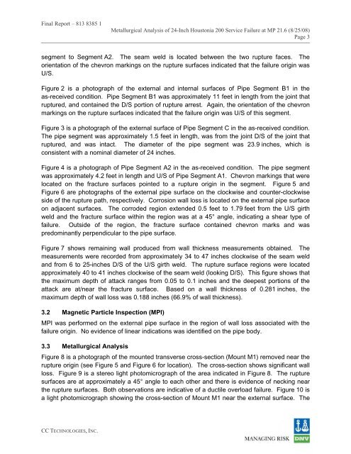
Final <strong>Report</strong> – 813 8385 1<br />
Metallurgical Analysis <strong>of</strong> 24-Inch Houstonia 200 Service <strong>Failure</strong> at MP 21.6 (8/25/08)<br />
Page 3<br />
segment to Segment A2. The seam weld is located between the two rupture faces. The<br />
orientation <strong>of</strong> the chevron markings on the rupture surfaces indicated that the failure origin was<br />
U/S.<br />
Figure 2 is a photograph <strong>of</strong> the external and internal surfaces <strong>of</strong> Pipe Segment B1 in the<br />
as-received condition. Pipe Segment B1 was approximately 11 feet in length from the joint that<br />
ruptured, and contained the D/S portion <strong>of</strong> rupture arrest. Again, the orientation <strong>of</strong> the chevron<br />
markings on the rupture surfaces indicated that the failure origin was U/S <strong>of</strong> this segment.<br />
Figure 3 is a photograph <strong>of</strong> the external surface <strong>of</strong> Pipe Segment C in the as-received condition.<br />
The pipe segment was approximately 1.5 feet in length, was from the joint D/S <strong>of</strong> the joint that<br />
ruptured, and was intact. The diameter <strong>of</strong> the pipe segment was 23.9 inches, which is<br />
consistent with a nominal diameter <strong>of</strong> 24 inches.<br />
Figure 4 is a photograph <strong>of</strong> Pipe Segment A2 in the as-received condition. The pipe segment<br />
was approximately 4.2 feet in length and U/S <strong>of</strong> Pipe Segment A1. Chevron markings that were<br />
located on the fracture surfaces pointed to a rupture origin in the segment. Figure 5 and<br />
Figure 6 are photographs <strong>of</strong> the external pipe surface on the clockwise and counter-clockwise<br />
side <strong>of</strong> the rupture path, respectively. Corrosion wall loss is located on the external pipe surface<br />
on adjacent surfaces. The corroded region extended 0.5 feet to 1.79 feet from the U/S girth<br />
weld and the fracture surface within the region was at a 45° angle, indicating a shear type <strong>of</strong><br />
failure. Outside <strong>of</strong> the region, the fracture surface contained chevron marks and was<br />
predominantly perpendicular to the pipe surface.<br />
Figure 7 shows remaining wall produced from wall thickness measurements obtained. The<br />
measurements were recorded from approximately 34 to 47 inches clockwise <strong>of</strong> the seam weld<br />
and from 6 to 25-inches D/S <strong>of</strong> the U/S girth weld. The rupture surface regions were located<br />
approximately 40 to 41 inches clockwise <strong>of</strong> the seam weld (looking D/S). This figure shows that<br />
the maximum depth <strong>of</strong> attack ranges from 0.05 to 0.1 inches and the deepest portions <strong>of</strong> the<br />
attack are at/near the fracture surface. Based on a wall thickness <strong>of</strong> 0.281 inches, the<br />
maximum depth <strong>of</strong> wall loss was 0.188 inches (66.9% <strong>of</strong> wall thickness).<br />
3.2 Magnetic Particle Inspection (MPI)<br />
MPI was performed on the external pipe surface in the region <strong>of</strong> wall loss associated with the<br />
failure origin. No evidence <strong>of</strong> linear indications was identified on the pipe body.<br />
3.3 Metallurgical Analysis<br />
Figure 8 is a photograph <strong>of</strong> the mounted transverse cross-section (Mount M1) removed near the<br />
rupture origin (see Figure 5 and Figure 6 for location). The cross-section shows significant wall<br />
loss. Figure 9 is a stereo light photomicrograph <strong>of</strong> the area indicated in Figure 8. The rupture<br />
surfaces are at approximately a 45° angle to each other and there is evidence <strong>of</strong> necking near<br />
the rupture surfaces. Both observations are indicative <strong>of</strong> a ductile overload failure. Figure 10 is<br />
a light photomicrograph showing the cross-section <strong>of</strong> Mount M1 near the external surface. The<br />
CC TECHNOLOGIES, INC.