troubleshooting the 8494 electric sidewinder - Elkhart Brass
troubleshooting the 8494 electric sidewinder - Elkhart Brass
troubleshooting the 8494 electric sidewinder - Elkhart Brass

Create successful ePaper yourself
Turn your PDF publications into a flip-book with our unique Google optimized e-Paper software.
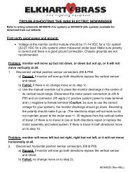
Problem; monitor will not stop at intended horizontal travel limits.<br />
5. Disconnect horizontal position sensor connectors J08 & P08. In connector P08<br />
check for hall sensor power (+7.5 to 12 VDC) at terminal 3 (red wire), left/right<br />
sensor signal voltage (+4.5 to 7.5 VDC) at terminal 2 (white wire), and ground at<br />
terminal 1 (black wire).<br />
a) Passed; if all values were within specifications. Move on to step 9b.<br />
b) Failed; one or more values did not meet specifications. Move on to step 6.<br />
6. Move to <strong>the</strong> next connector in <strong>the</strong> harness towards <strong>the</strong> monitor control module<br />
and check for hall sensor power (+7.5 to 12 VDC) at terminal position C, left/right<br />
sensor signal voltage (+4.5 to 7.5 VDC) at terminal position H, and ground at<br />
terminal position K. (There may be an extension harness or harnesses between<br />
connectors P4 and J4.)<br />
a) Passed; if all values were within specifications replace monitor harness and<br />
retest system.<br />
b) Failed; if all values were not within specifications;<br />
1. If this connector was on <strong>the</strong> output pigtail from <strong>the</strong> monitor<br />
control module <strong>the</strong>n replace <strong>the</strong> monitor control module, reconnect<br />
harnesses, and go back and repeat step 5.<br />
2. If this connector was on an extension harness move to next<br />
connector in <strong>the</strong> harness towards <strong>the</strong> monitor control module and<br />
check for hall sensor power (+7.5 to 12 VDC) at terminal position C,<br />
left/right sensor signal voltage (+4.5 to 7.5 VDC) at terminal position<br />
H, and ground at terminal position K. If all values were not within<br />
specifications move to next connector in <strong>the</strong> harness towards <strong>the</strong><br />
monitor control module and continue testing until you get <strong>the</strong> correct<br />
values in which case you replace <strong>the</strong> previous harness extension or<br />
until you reach <strong>the</strong> control module and still do not get <strong>the</strong> correct<br />
values in which case you replace <strong>the</strong> control module. In ei<strong>the</strong>r case<br />
reconnect harnesses, and go back and repeat step 5.