troubleshooting the 8494 electric sidewinder - Elkhart Brass
troubleshooting the 8494 electric sidewinder - Elkhart Brass
troubleshooting the 8494 electric sidewinder - Elkhart Brass

Create successful ePaper yourself
Turn your PDF publications into a flip-book with our unique Google optimized e-Paper software.
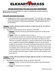
Passed; if all testing was within specifications replace <strong>the</strong> corresponding travel<br />
limit sensor and retest system.<br />
Failed; if all tests were not within specifications move to <strong>the</strong> connector J04 on<br />
<strong>the</strong> output pigtail from <strong>the</strong> monitor control module and retest using a meter<br />
attached to <strong>the</strong> up/down or left/right motor power terminals. See if placing a<br />
jumper between terminals H and K for left/right or J and K for up/down while<br />
corresponding motor output power is present will terminate power for that<br />
direction and only allow power in <strong>the</strong> opposite direction. If motor power is not<br />
terminated as described replace <strong>the</strong> monitor control module. Reconnect<br />
harnesses and sensor and retest to see if travel limits are now working.<br />
10. Find <strong>the</strong> wire for <strong>the</strong> function that is not working (left, right, up, down, fog, or<br />
stream) in connector P02. Placing a jumper between that terminal and <strong>the</strong> ground<br />
terminal in position C should result in <strong>the</strong> desired output on <strong>the</strong> terminals for motor<br />
power in connector J04. (Example; monitor won’t go left, a jumper between<br />
terminals in positions G (left) and C (ground) in connector P02 should result in<br />
Positive (+) motor power on terminal D and Negative (-) power on terminal C in<br />
connector J04.)<br />
a) Passed; if <strong>the</strong> correct motor power outputs are present on <strong>the</strong> correct<br />
terminals in connector J04 remove jumper and go on to step 11.<br />
b) Failed; if <strong>the</strong> correct motor power outputs are not present replace <strong>the</strong><br />
monitor control module and, reconnect all harnesses, & retest system.<br />
11. Reconnect <strong>the</strong> harnesses one at a time on <strong>the</strong> monitor side of <strong>the</strong> control module<br />
and check for correct motor power at <strong>the</strong> end terminals when using a jumper<br />
between <strong>the</strong> same terminals as in step 11. If correct motor power is not present<br />
replace <strong>the</strong> harness and repeat <strong>the</strong> test. Keep going until correct power is present at<br />
<strong>the</strong> appropriate motor power connector (P05, P07, or P09). Leave <strong>the</strong> meter<br />
connected to <strong>the</strong> motor power leads and go on to step 12.