X515C DF & X510C Manual - Lowrance
X515C DF & X510C Manual - Lowrance
X515C DF & X510C Manual - Lowrance

You also want an ePaper? Increase the reach of your titles
YUMPU automatically turns print PDFs into web optimized ePapers that Google loves.
www.lowrance.com<br />
Pub. 988-0151-451<br />
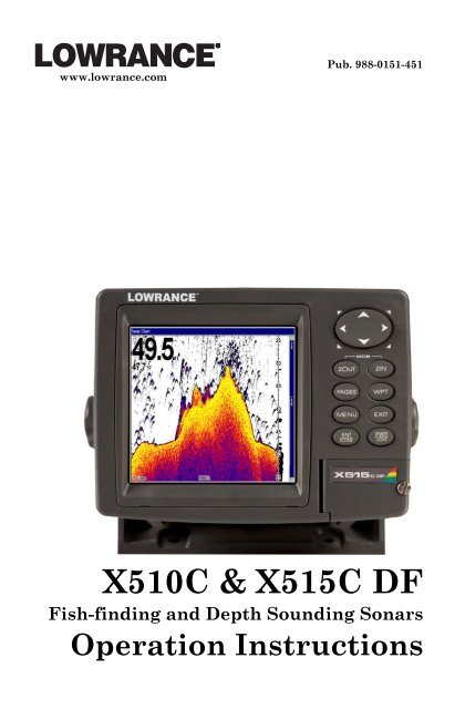
<strong>X510C</strong> & <strong>X515C</strong> <strong>DF</strong><br />
Fish-finding and Depth Sounding Sonars<br />
Operation Instructions
Copyright © 2006 <strong>Lowrance</strong> Electronics, Inc.<br />
All rights reserved.<br />
No part of this manual may be copied, reproduced, republished, transmitted<br />
or distributed for any purpose, without prior written consent of<br />
<strong>Lowrance</strong> Electronics. Any unauthorized commercial distribution<br />
of this manual is strictly prohibited.<br />
<strong>Lowrance</strong> ® is a registered trademark of <strong>Lowrance</strong> Electronics, Inc.<br />
<strong>Lowrance</strong> Electronics may find it necessary to change or end our policies,<br />
regulations, and special offers at any time. We reserve the right to<br />
do so without notice. All features and specifications subject to change<br />
without notice. All screens in this manual are simulated. On the cover:<br />
X515c<strong>DF</strong> shown.<br />
For free owner's manuals and other information,<br />
visit our web site:<br />
www.lowrance.com<br />
<strong>Lowrance</strong> Electronics Inc.<br />
12000 E. Skelly Dr.<br />
Tulsa, OK USA 74128-2486<br />
Printed in USA.
Table of Contents<br />
Section 1: Read Me First! ......................................................... 1<br />
Capabilities and Specifications: X-510c & X-515c<strong>DF</strong> ................. 2<br />
How Sonar Works.......................................................................... 3<br />
How to use this manual: typographical conventions .................. 4<br />
Section 2: Installation & Accessories.................................... 7<br />
Preparations .................................................................................. 7<br />
Transducer Installation ................................................................ 7<br />
Single-frequency transom installations............................... 8<br />
Dual-frequency transom installations ................................. 8<br />
Single-frequency trolling motor installations ..................... 8<br />
Shoot-through hull installations .......................................... 8<br />
Selecting a Transducer Location.............................................. 8<br />
How low should you go? ............................................................ 9<br />
Shoot-thru-hull vs. Transom Mounting................................. 10<br />
Transom Transducer Assembly And Mounting .................... 11<br />
Trolling Motor Bracket Installation (single-frequency only) 17<br />
Transducer Orientation and Fish Arches.............................. 17<br />
Shoot-Thru-Hull Preparation ................................................. 18<br />
Hulls With Floatation Materials........................................ 18<br />
Testing Determines Best Location......................................... 19<br />
Shoot-thru-hull Installation ................................................... 21<br />
Speed/Temperature Sensors ................................................. 22<br />
Optional Speed Sensor Installation ....................................... 22<br />
Power Connections...................................................................... 24<br />
Powering Your Display Unit ...................................................... 25<br />
Power Diagram A ........................................................................ 27<br />
Power Diagram B ........................................................................ 28<br />
Powering a NMEA 2000 Network Bus ...................................... 28<br />
NMEA 0183 Cable Connections ................................................. 29<br />
Mounting the Unit: Bracket, In-Dash or Portable.................... 29<br />
Other Accessories ........................................................................ 33<br />
Cleaning Towel........................................................................ 33<br />
Face Cover ................................................................................... 33<br />
Section 3: Basic Sonar Operation ........................................ 35<br />
Keyboard...................................................................................... 35<br />
Power/lights on and off ............................................................... 36<br />
Menus........................................................................................... 36<br />
Main Menu............................................................................... 36<br />
Sonar Menu.............................................................................. 38<br />
Pages ............................................................................................ 39<br />
Basic Sonar Quick Reference ..................................................... 43<br />
Sonar Operations ........................................................................ 44<br />
i
Fish Symbols vs. Full Sonar Chart ........................................ 46<br />
Other Free Training Aids ....................................................... 47<br />
Section 4: Sonar Options & Other Features...................... 49<br />
ASP (Advanced Signal Processing) ..................................... 49<br />
Alarms.......................................................................................... 50<br />
Depth Alarms .......................................................................... 50<br />
Zone Alarm .............................................................................. 51<br />
Fish Alarm ............................................................................... 52<br />
Brightness.................................................................................... 53<br />
Calibrate Speed ........................................................................... 53<br />
Chart Speed ................................................................................. 54<br />
Colorline....................................................................................... 55<br />
Contrast ....................................................................................... 56<br />
Depth Cursor ............................................................................... 56<br />
Depth Range - Automatic ........................................................... 56<br />
Depth Range - <strong>Manual</strong>................................................................ 57<br />
Depth Range - Upper and Lower Limits ................................... 57<br />
FasTrack................................................................................... 59<br />
Fish I.D. (Fish Symbols & Depths) ......................................... 60<br />
FishTrack.................................................................................. 61<br />
Frequency (Change Transducer Frequency) (X-515c<strong>DF</strong> only). 62<br />
HyperScroll............................................................................... 63<br />
Noise Rejection ............................................................................ 63<br />
Overlay Data ............................................................................... 63<br />
Ping Speed & HyperScroll....................................................... 65<br />
Pop-up Help ................................................................................. 67<br />
Reset Options............................................................................... 67<br />
Reset Water Distance.................................................................. 68<br />
Screen Contrast and Brightness ................................................ 68<br />
Sensitivity & Auto Sensitivity.................................................... 69<br />
Automatic Sensitivity ............................................................. 70<br />
Set Keel Offset............................................................................. 71<br />
Set Language............................................................................... 72<br />
Software Version Information.................................................... 73<br />
Sonar Chart Mode ....................................................................... 73<br />
Sonar Chart Display Options ..................................................... 74<br />
Full Sonar Chart ..................................................................... 74<br />
Split Zoom Sonar Chart .......................................................... 75<br />
Split Frequency Sonar Chart (X-515c<strong>DF</strong> only) ..................... 75<br />
Digital Data/Chart .................................................................. 76<br />
Customizing the Digital Data/Chart Screen ..................... 77<br />
Flasher ..................................................................................... 78<br />
Sonar with Custom Gauges ........................................................ 79<br />
ii
Radar............................................................................................ 81<br />
Sonar Simulator .......................................................................... 81<br />
Stop Chart.................................................................................... 82<br />
Surface Clarity ............................................................................ 82<br />
Transducer Type (X-515c<strong>DF</strong> only) ............................................. 83<br />
Transparency............................................................................... 84<br />
Units of Measure ......................................................................... 85<br />
Upper and Lower Limits............................................................. 86<br />
Zoom & Zoom Bar........................................................................ 86<br />
Zoom Pan ..................................................................................... 87<br />
Section 5: NMEA 2000 Menu.................................................. 89<br />
NMEA 2000 Menu....................................................................... 89<br />
Bus Setup..................................................................................... 89<br />
Engine & Tank Configuration.................................................... 90<br />
Tank Select .......................................................................... 91<br />
Tank Size ............................................................................. 91<br />
Set Configuration button .................................................... 91<br />
Device Configuration Menu.................................................... 92<br />
Device Information and Device Data ..................................... 92<br />
Fuel Management Menu............................................................. 93<br />
Tank Location ...................................................................... 93<br />
Fuel Added........................................................................... 93<br />
Add Fuel............................................................................... 94<br />
Fill Tank............................................................................... 94<br />
Adding Fuel to Tank ............................................................... 94<br />
Engine Operations................................................................... 94<br />
Engine Select ....................................................................... 94<br />
NMEA 2000 Alarms .................................................................... 95<br />
To set NMEA 2000 Alarm:.................................................. 96<br />
Waypoint Sharing ....................................................................... 96<br />
Backlight Synchronization ......................................................... 96<br />
Configuring EP Sensors.............................................................. 97<br />
EP-35 Temperature Configuration ........................................ 97<br />
Advanced Options menu ......................................................... 97<br />
Instance................................................................................ 98<br />
Restore Defaults .................................................................. 98<br />
To restore default settings.................................................. 98<br />
EP-10 Fuel Flow Configuration.............................................. 98<br />
Advanced Options menu ......................................................... 99<br />
Instance................................................................................ 99<br />
Restore Defaults .................................................................. 99<br />
EP-15 Fluid Level Configuration ......................................... 100<br />
Advanced Options menu ....................................................... 102<br />
iii
Instance.............................................................................. 102<br />
Restore Defaults ................................................................ 102<br />
To restore default settings:............................................... 102<br />
Suzuki Engine Interface Configuration............................... 103<br />
Advanced Options menu ....................................................... 104<br />
Instance.............................................................................. 104<br />
Restore Defaults ................................................................ 104<br />
Calibrating EP Sensors............................................................. 105<br />
EP-10 Fuel Flow Calibration................................................ 105<br />
EP-15 Fluid Level Calibration ............................................. 106<br />
2-Point Calibration............................................................ 106<br />
3-Point Calibration................................................................ 107<br />
5-Point Calibration............................................................ 108<br />
Fuel Flow Calibration in a Suzuki Engine Interface.......... 109<br />
Engine Trim Calibration....................................................... 110<br />
Reset Trim Calibration ......................................................... 111<br />
Bennett Trim Tabs Calibration............................................ 111<br />
Section 6: Sonar Troubleshooting ..................................... 113<br />
NOTICE!<br />
The storage and operation temperature range for your unit is from -20<br />
degrees to +167 degrees Fahrenheit (-28 degrees to +75 degrees<br />
Celsius). Extended storage or operation in temperatures higher or lower<br />
than specified will damage the liquid crystal display in your unit. This<br />
type of damage is not covered by the warranty. For more information,<br />
contact the factory's Customer Service Department; phone numbers are<br />
listed on the last page of the manual.<br />
iv
Section 1: Read Me First!<br />
How this manual can get you out on the water, fast!<br />
Welcome to the exciting world of digital sonar! We know you're anxious<br />
to begin finding fish, but we have a favor to ask. Before you grab your<br />
unit and begin installing it, please give us a moment or two to explain<br />
how our manual can help you get the best performance from your compact,<br />
wide-screen, fish finder.<br />
First, we want to thank you for buying a <strong>Lowrance</strong> sonar. Whether<br />
you're a first time user or a professional fisherman, you'll discover that<br />
your unit is easy to use, yet capable of handling demanding sonar<br />
tasks. You won't find another sonar unit with this much power and this<br />
many features for this price!<br />
Our goal for this book is to get you on the water fast, with a minimum<br />
of fuss. Like you, we'd rather spend more time boating or fishing and<br />
less time reading the manual!<br />
So, we designed our book so that you don't have to read the whole thing<br />
from front to back for the information you want. At the start (or end) of<br />
each segment, we'll tell you what content is coming up next. If it's a<br />
concept you're already familiar with, we'll show you how and where to<br />
skip ahead for the next important topic. We've also made it easy to look<br />
up any tips you may need from time to time. Here's how:<br />
The manual is organized into 6 sections. This first section is an introduction<br />
to the sonar unit. It tells you the basics you need to know before<br />
you can make the unit look below the surface to find some fish.<br />
Section 2 will help you install your unit and the transducer. We'll also<br />
tell you about some of the available accessories.<br />
Section 3 covers Basic Sonar Operation. It will show you how easy it is<br />
to run your sonar, right out of the box. This section features a one-page<br />
Sonar Quick Reference. (If you've already jumped ahead and figured<br />
out how to install the unit yourself, and you just can't wait<br />
any longer, turn to the Quick Reference on page 43 and head<br />
for the water with your sonar unit!)<br />
After you've gained some experience with your sonar, you'll want to<br />
check out Section 4, which discusses more advanced Sonar Options and<br />
Other Features.<br />
When you come to a sonar menu command on the unit's screen, you can<br />
look it up in the manual by skimming over the table of contents or index,<br />
just flipping through Section 3 or scanning through the sonar options in<br />
Section 4.<br />
1
If you're having difficulty with your sonar, you can find an answer to<br />
the most common problems in Section 5, Sonar Troubleshooting.<br />
Finally, in Section 6, we offer Supplemental Material, including a list of<br />
warranty and customer service information.<br />
Now, if you're into the fine details, glance over the next segment on specifications<br />
to see just how much sonar power your unit contains. It's important<br />
to us (and our power users), but, if you don't care how many watts of<br />
power the unit has, skip ahead to important information on how sonar<br />
works, on page 3.<br />
Capabilities and Specifications: X-510c & X-515c<strong>DF</strong><br />
General<br />
Display: ............................. 5.0" (12.7 cm) diagonal high color contrast<br />
Film SuperTwist; programmable to viewing<br />
preference.<br />
Resolution: ......................480 pixel x 480 pixel resolution ; 230,400 total<br />
pixels.<br />
Backlighting: ..................X-510c, X-515c<strong>DF</strong><br />
White LED backlit screen and keypad.<br />
Input power: ...................10 to 15 volts DC.<br />
Case size: .........................5.4" H x 6.9" W x 3.4" D (13.8 x 17.6 x 8.6<br />
cm); sealed and waterproof; suitable for<br />
saltwater use.<br />
Back-up memory:...........Built-in memory stores sonar records for<br />
decades.<br />
Languages: ......................10; menu languages selectable by user.<br />
Sonar<br />
Frequency: ......................50/200 kHz for X-515c<strong>DF</strong>; 200 kHz for X-<br />
510c.<br />
Transducers:...................A dual-frequency Skimmer ® transducer with<br />
built-in temperature sensor is packed with<br />
the X-515c<strong>DF</strong>. It has 35°/12° cone angles. A<br />
single-frequency with built-in temperature<br />
sensor is packed with the X-510c. It has a<br />
20° cone angle. Transducers operate at<br />
speeds up to 70 mph (61 kts).<br />
2
Transmitter:....................X-515c<strong>DF</strong>:<br />
4,000 watts peak-to-peak/500 watts RMS.<br />
X-510c:<br />
2,400 watts peak-to-peak/300 watts RMS.<br />
Sonar sounding<br />
depth capability:............X-515cC<strong>DF</strong>: 2,500 feet (762 meters).<br />
X-510c: 800 feet (244 meters).<br />
Actual capability depends on transducer configuration<br />
and installation, bottom composition<br />
and water conditions. All sonar units<br />
typically read deeper in fresh water than in<br />
salt water.<br />
Depth display: ................Continuous display.<br />
Audible alarms:..............Deep/shallow/fish/zone.<br />
Automatic ranging: .......Yes, with instant screen updates.<br />
Auto bottom track: ........Yes.<br />
Zoom bottom track:.......Yes.<br />
Split-screen zoom: .........Yes.<br />
Surface water temp: .....Yes.<br />
Speed/distance log: .......Optional (requires optional speed sensor).<br />
NOTICE!<br />
The storage temperature range for your unit is from -4 degrees to +167<br />
degrees Fahrenheit (-20 degrees to +75 degrees Celsius). Extended<br />
storage in temperatures higher or lower than specified will damage the<br />
liquid crystal display in your unit. This type of damage is not covered by<br />
the warranty. For more information, contact the factory's Customer<br />
Service Department; phone numbers are listed on the last page.<br />
How Sonar Works<br />
Sonar has been around since the 1940s, so if you already know how it<br />
works, skip ahead to the next segment on the typographical conventions<br />
used in this manual. But, if you've never owned a sonar fish finder, this<br />
segment will tell you the under water basics.<br />
Sonar is an abbreviation for SOund NAvigation and Ranging, a technology<br />
developed during World War II for tracking enemy submarines.<br />
(<strong>Lowrance</strong> developed the world's first transistorized sportfishing sonar in<br />
1957.) A sonar consists of a transmitter, transducer, receiver and display.<br />
In simple terms, here's how it finds the bottom, or the fish:<br />
3
The transmitter emits an electrical impulse, which the transducer converts<br />
into a sound wave and sends into the water. (The sound frequency<br />
can't be heard by humans or fish.) The sound wave strikes an object<br />
(fish, structure, bottom) and bounces back to the transducer, which<br />
converts the sound back into an electrical signal.<br />
The receiver amplifies this return signal, or echo, and sends it to the<br />
display, where an image of the object appears on the scrolling sonar<br />
chart. The sonar's microprocessor calculates the time lapse between the<br />
transmitted signal and echo return to determine the distance to the<br />
object. The whole process repeats itself several times each second.<br />
How to use this manual: typographical conventions<br />
Many instructions are listed as numbered steps. The keypad and arrow<br />
"keystrokes" appear as boldface type. So, if you're in a real hurry (or<br />
just need a reminder), you can skim the instructions and pick out what<br />
menu command to use by finding the boldface command text. The following<br />
paragraphs explain how to interpret the text formatting for<br />
those commands and other instructions:<br />
Arrow Keys<br />
The arrow keys control a horizontal line depth cursor on the sonar<br />
screen. The arrow keys also help you move around the menus so you<br />
can execute different commands. They are represented by symbols like<br />
these, which denote the down arrow key, the up arrow, the left arrow<br />
and the right arrow: ↓ ↑ ← →.<br />
Keyboard<br />
The other keys perform a variety of functions. When the text refers to a<br />
key to press, the key is shown in bold, sans serif type. For example, the<br />
"Enter/Icons" key is shown as ENT and the "Menu" key is shown as MENU.<br />
Menu Commands<br />
A menu command or a menu option will appear in small capital letters,<br />
in a bold sans serif type like this: DEPTH CURSOR. These indicate that you<br />
are to select this command or option from a menu or take an action of<br />
some kind with the menu item. Text that you may need to enter or file<br />
names you need to select are show in italic type, such as data type.<br />
Instructions = Menu Sequences<br />
Most functions you perform with the sonar unit are described as a sequence<br />
of key strokes and selecting menu commands. We've written<br />
them in a condensed manner for quick and easy reading.<br />
4
For example, instructions for turning on the Fish ID feature would<br />
look like this:<br />
1. From the Sonar Page, press MENU|↓ to SONAR FEATURES|ENT.<br />
2. Press → to FISH SYMBOLS|ENT|EXIT|EXIT.<br />
Translated into complete English, step 1 above would mean: "Start on<br />
the Sonar Page. Press the Menu key then repeatedly press (or press and<br />
hold) the down arrow key to scroll down the menu and select (highlight)<br />
the Sonar Features menu command. Then press the Enter key."<br />
Step 2 would mean: "Press the right arrow key to select (highlight) the<br />
Fish ID symbols command. Next, press the Enter key, then press the<br />
Exit key twice."<br />
5
Notes<br />
6
Section 2:<br />
Installation & Accessories<br />
Preparations<br />
You can install the sonar system in some other order if you prefer, but<br />
we recommend this installation sequence:<br />
Caution:<br />
You should read over this entire installation section before drilling<br />
any holes in your vessel!<br />
1. Determine the approximate location for the sonar unit, so you can<br />
plan how and where to route the cables for the transducer and power.<br />
This will help you make sure you have enough cable length for the desired<br />
configuration.<br />
2. Determine the approximate location for the transducer and its cable<br />
route.<br />
3. Determine the location of your battery or other power connection,<br />
along with the power cable route.<br />
4. Install the transducer and route the transducer cable to the sonar<br />
unit.<br />
5. Install the power cable and route it to the sonar unit.<br />
6. Mount the sonar unit.<br />
Transducer Installation<br />
These instructions will help you install your Skimmer ® transducer on a<br />
transom, on a trolling motor or inside a hull. These instructions cover<br />
both single- and dual-frequency Skimmer transducers. Please read all<br />
instructions before proceeding with any installation.<br />
The smaller single-frequency Skimmers typically use a one-piece,<br />
stainless steel mounting bracket. The larger dual-frequency Skimmers<br />
typically use a two-piece, plastic mounting bracket. The trolling motor<br />
mount uses a one-piece plastic bracket with an adjustable strap.<br />
These are all "kick-up" mounting brackets. They help prevent damage<br />
if the transducer strikes an object while the boat is moving. If the<br />
transducer does "kick-up," the bracket can easily be pushed back into<br />
place without tools.<br />
Read these instructions carefully before attempting the installation.<br />
Determine which of the mounting positions is right for your boat. Remember,<br />
the transducer installation is the most critical part of<br />
a sonar installation.<br />
7
NOTE:<br />
The following installation types also call for these recommended<br />
tools and required supplies that you must provide (supplies listed<br />
here are not included):<br />
Single-frequency transom installations<br />
Tools include: two adjustable wrenches, drill, #29 (0.136") drill bit, flathead<br />
screwdriver. Supplies: high quality, marine grade above- or belowwaterline<br />
sealant/adhesive compound.<br />
Dual-frequency transom installations<br />
Tools: two adjustable wrenches, drill, #20 (0.161") drill bit, flat-head<br />
screwdriver. Supplies: four, 1" long, #12 stainless steel slotted wood<br />
screws, high quality, marine grade above- or below-waterline sealant/adhesive<br />
compound.<br />
Single-frequency trolling motor installations<br />
Tools: two adjustable wrenches, flat-head screwdriver. Supplies: plastic<br />
cable ties.<br />
Shoot-through hull installations<br />
Tools: these will vary depending on your hull's composition. Consult your<br />
boat dealer or manufacturer. Other tools are a wooden craft stick or<br />
similar tool for stirring and applying epoxy, and a paper plate or piece<br />
of cardboard to mix the epoxy on. Supplies: rubbing alcohol, 100 grit<br />
sandpaper, specially formulated epoxy adhesive available from LEI (see<br />
ordering information on the inside back cover). A sandwich hull also<br />
requires polyester resin.<br />
Selecting a Transducer Location<br />
1. The location must be in the water at all times, at all operating speeds.<br />
2. The transducer must be placed in a location that has a smooth flow<br />
of water at all times. If the transducer is not placed in a smooth flow<br />
of water, interference caused by bubbles and turbulence will show on<br />
the sonar's display in the form of random lines or dots whenever the<br />
boat is moving.<br />
NOTE:<br />
Some aluminum boats with strakes or ribs on the outside of the<br />
hull create large amounts of turbulence at high speed. These boats<br />
typically have large outboard motors capable of propelling the boat<br />
at speeds faster than 35 mph. Typically, a good transom location on<br />
aluminum boats is between the ribs closest to the engine.<br />
3. The transducer should be installed with its face pointing straight<br />
down, if possible. For shoot-thru applications: Many popular fishing<br />
8
oat hulls have a flat keel pad that offers a good mounting surface. On<br />
vee hulls, try to place the transducer where the deadrise is 10° or less.<br />
Deadrise less than 10°<br />
Strakes<br />
Pad<br />
Left, vee pad hull; right, vee hull. A pod style transducer is shown<br />
here, but the principle is the same for Skimmers inside a hull.<br />
4. If the transducer is mounted on the transom, make sure it doesn't<br />
interfere with the trailer or hauling of the boat. Also, don't mount it<br />
closer than approximately one foot from the engine's lower unit. This<br />
will prevent cavitation (bubble) interference with propeller operation.<br />
5. If possible, route the transducer cable away from other wiring on the<br />
boat. Electrical noise from engine wiring, bilge pumps and aerators<br />
can be displayed on the sonar's screen. Use caution when routing the<br />
transducer cable around these wires.<br />
CAUTION: Clamp the transducer<br />
cable to transom near<br />
the transducer. This will help<br />
prevent the transducer from<br />
entering the boat if it is<br />
knocked off at high speed.<br />
Good location<br />
Good<br />
location<br />
Poor location<br />
Poor angle Good location<br />
Good and poor transducer locations.<br />
How low should you go?<br />
For most situations, you should install your Skimmer transducer so<br />
that its centerline is level with the bottom of the boat hull. This will<br />
usually give you the best combination of smooth water flow and protection<br />
from bangs and bumps.<br />
9
Transducer<br />
centerline<br />
Transom<br />
Hull bottom<br />
Align transducer centerline with hull bottom.<br />
However, there are times when you may need to adjust the transducer<br />
slightly higher or lower. (The slots in the mounting brackets allow you<br />
to loosen the screws and slide the transducer up or down.) If you frequently<br />
lose bottom signal lock while running at high speed, the transducer<br />
may be coming out of the water as you cross waves or wakes.<br />
Move the transducer a little lower to help prevent this.<br />
If you cruise or fish around lots of structure and cover, your transducer<br />
may be frequently kicking up from object strikes. If you wish, you may<br />
move the transducer a little higher for more protection.<br />
There are two extremes you should avoid. Never let the edge of the<br />
mounting bracket extend below the bottom of the hull. Never let the<br />
bottom – the face – of the transducer rise above the bottom of the hull.<br />
Shoot-thru-hull vs. Transom Mounting<br />
In a shoot-thru-hull installation, the transducer is bonded to the inside<br />
of the hull with epoxy. The sonar "ping" signal actually passes through<br />
the hull and into the water. This differs from a bolt-thru-hull installation<br />
(often called simply "thru-hull"). In that case, a hole is cut in the<br />
hull and a specially designed transducer is mounted through the hull<br />
with a threaded shaft and nut. This puts the transducer in direct contact<br />
with the water.<br />
Typically, shoot-thru-hull installations give excellent high speed operation<br />
and good to excellent depth capability. There is no possibility of<br />
transducer damage from floating objects, as there is with a transommounted<br />
transducer. A transducer mounted inside the hull can't be<br />
knocked off when docking or loading on a trailer.<br />
However, the shoot-thru-hull installation does have its drawbacks.<br />
First, some loss of sensitivity does occur, even on the best hulls. This<br />
varies from hull to hull, even from different installations on the same<br />
hull. This is caused by differences in hull lay-up and construction.<br />
Second, the transducer angle cannot be adjusted for the best fish<br />
arches on your sonar display. (This is not an issue for flasher-style<br />
10
sonars.) Lack of angle adjustment can be particularly troublesome on<br />
hulls that sit with the bow high when at rest or at slow trolling speeds.<br />
Third, a transducer CAN NOT shoot through wood and metal hulls.<br />
Those hulls require either a transom mount or a thru-hull installation.<br />
Fourth, if your Skimmer transducer has a built in temp sensor, it will<br />
only show the temperature of the bilge, not the water surface temp.<br />
Follow the testing procedures listed in the shoot-thru-hull installation<br />
section at the end of this lesson to determine if you can satisfactorily<br />
shoot through the hull.<br />
Transom Transducer Assembly And Mounting<br />
The best way to install these transducers is to loosely assemble all of the<br />
parts first, place the transducer's bracket against the transom and see if<br />
you can move the transducer so that it's parallel with the ground.<br />
The following instructions sometimes vary depending on the mounting<br />
bracket that came with your transducer. Single-frequency Skimmers<br />
come with a one-piece stainless steel bracket, while dual-frequency<br />
Skimmers come with a two-piece plastic mounting bracket. Use the set of<br />
instructions that fits your model.<br />
1. Assembling the bracket.<br />
A. One-piece bracket: Press the two small plastic ratchets into the<br />
sides of the metal bracket as shown in the following illustration. Notice<br />
there are letters molded into each ratchet. Place each ratchet into the<br />
bracket with the letter "A" aligned with the dot stamped into the metal<br />
bracket. This position sets the transducer's coarse angle adjustment for a<br />
14° transom. Most outboard and stern-drive transoms have a 14° angle.<br />
Dot<br />
Align plastic ratchets in bracket.<br />
B. Two-piece bracket: Locate the four plastic ratchets in the transducer's<br />
hardware package. Press two ratchets into the sides of the plastic<br />
bracket and two on either side of the transducer as shown in the following<br />
illustrations. Notice there are letters molded into each ratchet.<br />
Place the ratchets into the bracket with the letter "A" aligned with the<br />
11
alignment mark molded into the bracket. Place the ratchets onto the<br />
transducer with the letter "A" aligned with the 12 o'clock position on<br />
the transducer stem. These positions set the transducer's coarse angle<br />
adjustment for a 14° transom. Most outboard and stern-drive transoms<br />
have a 14° angle.<br />
Alignment<br />
positions<br />
Alignment letters<br />
Transducer<br />
Transducer bracket<br />
Insert and align ratchets.<br />
Transducer<br />
Transducer<br />
bracket<br />
Ratchet<br />
Ratchet<br />
Add ratchets to bracket and transducer.<br />
2. Aligning the transducer on the transom.<br />
A. One-piece bracket: Slide the transducer between the two ratchets.<br />
Temporarily slide the bolt though the transducer assembly and<br />
hold it against the transom. Looking at the transducer from the side,<br />
check to see if it will adjust so that its face is parallel to the ground.<br />
If it does, then the "A" position is correct for your hull.<br />
If the transducer's face isn't parallel with the ground, remove the<br />
transducer and ratchets from the bracket.<br />
12
Place the ratchets into the holes in the bracket with the letter "B"<br />
aligned with the dot stamped in the bracket.<br />
Reassemble the transducer and bracket and place them against the<br />
transom. Again, check to see if you can move the transducer so it's<br />
parallel with the ground. If you can, then go to step 3A. If it doesn't,<br />
repeat step 2A, but use a different alignment letter until you can<br />
place the transducer on the transom correctly.<br />
Ratchets<br />
Insert bolt and check transducer position on transom.<br />
B. Two-piece bracket: Assemble the transducer and bracket as shown<br />
in the following figure. Temporarily slide the bolt though the transducer<br />
assembly but don't tighten the nut at this time. Hold the assembled<br />
transducer and bracket against the transom. Looking at the transducer<br />
from the side, check to see if it will adjust so that its face is parallel to<br />
the ground. If it does, then the "A" positions are correct for your hull.<br />
If the transducer's face isn't parallel with the ground, remove and<br />
disassemble the transducer and ratchets. Place the ratchets into the<br />
bracket holes with the letter "B" aligned with the bracket alignment<br />
mark. Place them on the transducer aligned with the 12 o'clock position<br />
on the transducer stem.<br />
Reassemble the transducer and bracket and place them against the<br />
transom. Again, check to see if you can move the transducer so it's<br />
parallel with the ground. If you can, then go to step 3B. If it doesn't,<br />
repeat step 2B, but use a different alignment letter until you can<br />
place the transducer on the transom correctly.<br />
13
Bolt<br />
Flat washer<br />
Lock washer<br />
Nut<br />
Flat washer<br />
Assemble transducer and bracket.<br />
3. Assembling the transducer.<br />
A. One-piece bracket: Once you determine the correct position for<br />
the ratchets, assemble the transducer as shown in the following figure.<br />
Don't tighten the lock nut at this time.<br />
Metal<br />
Nut washer<br />
Rubber<br />
washers<br />
Metal washer<br />
Bolt<br />
Assemble transducer and bracket.<br />
B. Two-piece bracket: Once you determine the correct position for<br />
the ratchets, assemble the transducer as shown in the figure in step<br />
2B. Don't tighten the lock nut at this time.<br />
4. Drilling mounting holes.<br />
Hold the transducer and bracket assembly against the transom. The<br />
transducer should be roughly parallel to the ground. The transducer's<br />
centerline should be in line with the bottom of the hull. Don't<br />
let the bracket extend below the hull!<br />
Mark the center of each slot for the mounting screw pilot holes. You<br />
will drill one hole in the center of each slot.<br />
Drill the holes. For the one-piece bracket, use the #29 bit (for the #10<br />
screws). For the two-piece bracket, use the #20 bit (for the #12 screws).<br />
14
Transom<br />
Transom<br />
Position transducer mount on transom and mark mounting holes.<br />
Side view shown, left, and seen from above at right.<br />
5. Attaching transducer to transom.<br />
A. One-piece bracket: Remove the transducer from the bracket and<br />
re-assemble it with the cable passing through the bracket over the<br />
bolt as shown in the following figures.<br />
For single-frequency Skimmer, route cable over bolt and through<br />
bracket. Side view shown, left, and seen from above at right.<br />
Both bracket types: Attach the transducer to the transom. Slide the<br />
transducer up or down until it's aligned properly with the bottom of<br />
the hull as shown in the preceding and following figures. Tighten the<br />
bracket's mounting screws, sealing them with the sealant.<br />
Adjust the transducer so that it's parallel to the ground and tighten<br />
the nut until it touches the outer washer, then add 1/4 turn. Don't<br />
over tighten the lock nut! If you do, the transducer won't "kick-up" if<br />
it strikes an object in the water.<br />
15
Bottom<br />
of<br />
hull<br />
Flat-bottom hull<br />
Deep-"vee" hull<br />
Align transducer centerline with hull bottom and attach transducer to<br />
transom. Rear view of dual-frequency Skimmer shown.<br />
6. Route the transducer cable through or over the transom to the sonar<br />
unit. Make sure to leave some slack in the cable at the transducer. If<br />
possible, route the transducer cable away from other wiring on the<br />
boat. Electrical noise from the engine's wiring, bilge pumps, VHF radio<br />
wires and cables, and aerators can be picked up by the sonar. Use caution<br />
when routing the transducer cable around these wires.<br />
WARNING:<br />
Clamp the transducer cable to the transom close to the<br />
transducer. This can prevent the transducer from entering<br />
the boat if it is knocked off at high speed.<br />
If you need to drill a hole in the transom to pass the connector through,<br />
the required hole size be 1".<br />
Caution:<br />
If you drill a hole in the transom for the cable, make sure it is<br />
located above the waterline. After installation, be sure to seal the<br />
hole with the same marine grade above- or below-waterline<br />
sealant used for the mounting screws.<br />
7. Make a test run to determine the results. If the bottom is lost at<br />
high speed, or if noise appears on the display, try sliding the transducer<br />
bracket down. This puts the transducer deeper into the water,<br />
hopefully below the turbulence causing the noise. Don't allow the<br />
transducer bracket to go below the bottom of the hull!<br />
16
Trolling Motor Bracket Installation<br />
(single-frequency only)<br />
1. Attach the optional TMB-S bracket to the transducer as shown in the<br />
following figure, using the hardware supplied with the transducer.<br />
(Note: The internal tooth washer is supplied with the TMB-S.)<br />
TMB-S bracket<br />
Internal tooth washer<br />
Bolt<br />
Nut<br />
Flat washer<br />
Attach motor mounting bracket to transducer.<br />
2. Slide the adjustable strap supplied with the TMB-S through the slot<br />
in the transducer bracket and wrap it around the trolling motor. Position<br />
the transducer to aim straight down when the motor is in the<br />
water. Tighten the strap securely.<br />
3. Route the transducer cable alongside the trolling motor shaft. Use<br />
plastic ties (not included) to attach the transducer cable to the trolling<br />
motor shaft. Make sure there is enough slack in the cable for the<br />
motor to turn freely. Route the cable to the sonar unit and the transducer<br />
is ready for use.<br />
Transducer mounted on trolling motor, side view.<br />
Transducer Orientation and Fish Arches<br />
If you do not get good fish arches on your display, it could be because<br />
the transducer is not parallel with the ground when the boat is at rest<br />
in the water or at slow trolling speeds.<br />
17
Partial fish arches<br />
Transducer aimed<br />
too far back<br />
Transducer aimed<br />
too far forward<br />
Full fish arch<br />
Proper transducer angle<br />
Transducer angles and their effects on fish arches.<br />
If the arch slopes up – but not back down – then the front of the transducer<br />
is too high and needs to be lowered. If only the back half of the<br />
arch is printed, then the nose of the transducer is angled too far down<br />
and needs to be raised.<br />
NOTE:<br />
Periodically wash the transducer's face with soap and water to remove<br />
any oil film. Oil and dirt on the face will reduce the sensitivity<br />
or may even prevent operation.<br />
Shoot-Thru-Hull Preparation<br />
Hulls With Floatation Materials<br />
The transducer installation inside a fiberglass hull must be in an area<br />
that does not have air bubbles in the resin or separated fiberglass layers.<br />
The sonar signal must pass through solid fiberglass. A successful<br />
transducer installation can be made on hulls with flotation materials<br />
(such as plywood, balsa wood or foam) between layers of fiberglass if<br />
the material is removed from the chosen area. See the following figure.<br />
18
WARNING:<br />
Do not remove any material from your inner hull unless<br />
you know the hull's composition. Careless grinding or<br />
cutting on your hull can result in damage that could<br />
sink your boat. Contact your boat dealer or manufacturer<br />
to confirm your hull specifications.<br />
Fill with resin<br />
Flotation material<br />
Fill with<br />
Inner hull<br />
Epoxy to hull first<br />
Outer hull<br />
Epoxy the transducer to a solid portion of the hull.<br />
For example, some (but not all) manufacturers use a layer of fiberglass,<br />
then a core of balsa wood, finishing with an outer layer of fiberglass.<br />
Removing the inner layer of fiberglass and the balsa wood core exposes<br />
the outer layer of fiberglass. The transducer can then be epoxied directly<br />
to the outer layer of fiberglass. After the epoxy cures for 24<br />
hours, fill the remaining space with polyester resin. When the job is<br />
finished, the hull is watertight and structurally sound. Remember, the<br />
sonar signal must pass through solid fiberglass. Any air bubbles in the<br />
fiberglass or the epoxy will reduce or eliminate the sonar signals.<br />
Testing Determines Best Location<br />
Ideally, the shoot-thru transducer should be installed as close to the<br />
transom as possible, close to the centerline. This will give you the best<br />
performance during high speed maneuvers.<br />
Transducer location<br />
(high speed)<br />
Transducer location<br />
(trolling speed)<br />
Shoot-thru-hull transducer locations for<br />
high speed or trolling speed operation.<br />
19
To choose the proper location for shoot-thru-hull mounting, follow these<br />
testing procedures: (You may need a helper to complete these steps.)<br />
1. Anchor the boat in about 30 feet of water. Add a little water to the sump<br />
of the boat. Plug the transducer into the sonar unit, turn it on, then<br />
hold the transducer over the side of the boat in the water. Adjust the<br />
sensitivity and range controls until a second bottom echo is seen on the<br />
display. (You'll need to turn off Auto Sensitivity, Auto Depth Range and<br />
ASP. Try a range setting that is two to three times the water depth.<br />
The harder (more rocky) the bottom, the easier it will be to get a second<br />
bottom signal.) Don't touch the controls once they've been set.<br />
True bottom<br />
Second bottom<br />
<strong>Manual</strong> range setting<br />
Example of a second bottom signal. Unit is in 30 feet of water, with<br />
range set at 80 feet and sensitivity set at 87 percent.<br />
2. Next, take the transducer out of the water and place it in the water in<br />
the sump of the boat, face down. (The transducer face is shown in the<br />
figure on the following page.) Notice how the signal strength decreases.<br />
The second bottom signal will probably disappear and the bottom signal<br />
intensity will likely decrease.<br />
3. Now move the transducer around to find the best location with the<br />
strongest possible bottom signal. If you find a spot with an acceptable<br />
bottom signal, mark the location and move on to step 4.<br />
If you can't get an acceptable bottom signal, try turning up the sensitivity<br />
by three or five keystrokes and then move the transducer around<br />
once more. If you find a spot that works, mark it and move on to step 4.<br />
If you have to turn up sensitivity by more than five keystrokes to get a<br />
good signal, the transducer should be mounted on the outside of the<br />
hull. This is especially true if you have to turn sensitivity all the way<br />
up to get a decent bottom signal.<br />
4. Most people can get good results by following steps 1 through 3, so this<br />
step is optional. If you want to make an extra effort to be absolutely<br />
20
sure that your selected location will work under all conditions, make a<br />
test run with the boat on plane and observe the bottom signal. You'll<br />
need to figure some way to prop the transducer into position while you<br />
make your test run. (A brick or two might be sufficient to hold it in<br />
place.)<br />
5. When you're satisfied with a location, mark it and proceed with<br />
the installation.<br />
Shoot-thru-hull Installation<br />
If you are installing the transducer on a hull with floatation material<br />
sandwiched within the hull, refer to the text "Hulls With Flotation Materials"<br />
beginning on page 18.<br />
1. Make sure the area is clean, dry and free of oil or grease, then sand<br />
both the inside surface of the hull and the face of the transducer with<br />
100 grit sandpaper. The sanded hull area should be about 1-1/2 times<br />
the diameter of the transducer. The surface of the hull must be flat<br />
so the entire transducer face is in contact with the hull prior to bonding.<br />
After sanding, clean the hull and transducer with rubbing alcohol<br />
to remove any sanding debris.<br />
Spread epoxy here<br />
Sand this surface<br />
(unit's face)<br />
Orient the Skimmer<br />
with the nose facing<br />
the bow of the boat.<br />
To bow<br />
Epoxy transducer to hull.<br />
WARNING:<br />
Use only the epoxy available from LEI. It has been formulated<br />
to work with these installation procedures.<br />
Other epoxy types may be too thin or may not cure to<br />
the right consistency for optimum transducer performance.<br />
21
2. The epoxy consists of the epoxy itself and a hardener. Remove the<br />
two compounds from the package and place them on the paper plate.<br />
Thoroughly stir the two compounds together until the mixture has a<br />
uniform color and consistency. Do not mix too fast or bubbles will<br />
form in the epoxy. After mixing, you have 20 minutes to complete the<br />
installation before the epoxy becomes unworkable.<br />
Spread a thin layer of epoxy (about 1/16" or 1.5 mm thick) on the face<br />
of the transducer as shown in the previous figure. Make sure there<br />
are no air pockets in the epoxy layer! Then, apply the remaining epoxy<br />
to the sanded area on the hull.<br />
3. Press the transducer into the epoxy, twisting and turning it to force<br />
any air bubbles out from under the transducer face. Stop pressing<br />
when you bottom out on the hull. When you're finished, the face of<br />
the transducer should be parallel with the hull, with a minimum<br />
amount of epoxy between the hull and transducer.<br />
4. Apply a weight, such as a brick, to hold the transducer in place while<br />
the epoxy cures. Be careful not to bump the transducer while the epoxy<br />
is wet. Leave the weight in place for a minimum of three hours.<br />
Allow the epoxy to cure for 24 hours before moving the boat.<br />
5. After the epoxy has cured, route the cable to the sonar unit and it's<br />
ready to use.<br />
Speed/Temperature Sensors<br />
Optional Speed Sensor Installation<br />
All the units in this series can display speed and distance traveled, but<br />
only the X-515c<strong>DF</strong> comes packed with a speed sensor. If you wish to<br />
purchase an optional additional sensor for your unit, refer to the accessory<br />
ordering information inside the back cover of this manual. The<br />
following instructions describe how to install the speed sensor.<br />
Recommended tools for this job include: drill, 7/8" drill bit, 1/8" drill bit<br />
for pilot holes, screwdriver. Required supplies for this job include: four<br />
#8 stainless steel wood screws (3/4" long), high quality, marine grade<br />
above- or below-waterline sealant.<br />
First find a location on the boat's transom where the water flow is<br />
smoothest. Don't mount the sensor behind strakes or ribs. These will<br />
disturb the water flow to the speed sensor. Make sure the sensor will<br />
remain in the water when the boat is on plane. Also make sure the location<br />
doesn't interfere with the boat's trailer. Typically, the sensor is<br />
mounted about one foot to the side of the transom's centerline. Once<br />
you've determined the proper location for the unit, place the sensor on<br />
22
the transom. The bottom of the bracket should be flush with the hull's<br />
bottom. Using the sensor as a template, mark the hull for the screws'<br />
pilot holes. Drill four 1/8" holes, one in each end of the slots.<br />
Mount the sensor to the hull using #8 stainless steel wood screws (not<br />
included). Use a high quality, marine grade above- or below-waterline<br />
sealant to seal the screws. Make sure the sensor is flush with the bottom<br />
of the hull and tighten the screws.<br />
Good location<br />
Stern view showing good location for mounting sensor on transom.<br />
Transom<br />
Bottom of hull<br />
Speed sensor mounting configuration:<br />
side view (left) and rear view (right.)<br />
Bottom of hull<br />
If the base of the transom has a radius, fill the gap between the transom<br />
and the sensor with the sealant. This will help ensure a smooth<br />
water flow.<br />
Route the sensor's cable through or over the transom to the sonar unit.<br />
If you need to drill a hole in the transom to pass the connector through,<br />
the required hole size is 7/8".<br />
CAUTION:<br />
If you drill a hole in the transom for the cable, make sure it is<br />
located above the waterline. After installation, be sure to seal the<br />
hole with the same marine grade above- or below-waterline<br />
sealant used for the screws.<br />
The sensor is now ready for use. Connect the sensor to the sonar socket<br />
on the back of your unit and connect the transducer to the speed sensor's<br />
socket. If you have any questions concerning the installation of<br />
the sensor, please contact your local boat dealer.<br />
23
Sonar unit (rear view)<br />
Sonar socket<br />
Ethernet (future<br />
enhancement)<br />
SP-BL optional<br />
speed sensor<br />
Power/Data<br />
socket<br />
Network<br />
socket<br />
Display unit<br />
power cable<br />
NMEA 2000<br />
Power cable<br />
Data Cable<br />
Transducer<br />
Sonar unit cable connections.<br />
Power Connections<br />
Your unit comes with a power/data cable that splits into three<br />
branches, each with several exposed wires.<br />
The thicker three-wire cable (white, red and black) is the power supply<br />
for your display unit. This cable has no label.<br />
24
The thinner branch with three wires (red, black and shield) is the<br />
power cable for a NMEA 2000 network. It is labeled "NMEA 2000<br />
POWER."<br />
The branch with four wires (blue, yellow, orange, and shield) is a data<br />
cable, labeled "RS-232 COMM." It supports a serial communication<br />
port. This allows your unit to exchange NMEA 0183 data with another<br />
device, such as an autopilot, DSC marine radio or computer.<br />
To unit<br />
Display unit power wires:<br />
white, red and black<br />
The Power/Data cable for this unit.<br />
NOTE:<br />
There are two basic power connection options, which are shown in<br />
the following two diagrams. Read the following instructions<br />
carefully to determine which power connection applies to<br />
your unit. Depending on your configuration, you may not use all of<br />
these wires.<br />
Caution:<br />
All of the wires in the power/data cable have bare ends for easier<br />
installation. The bare ends on any unused wires could cause<br />
an electrical short if left exposed. To prevent this, you should<br />
cover the individual wire ends – either by capping them with<br />
wire nuts, wrapping them with electrical tape or both. (You<br />
should cut off the bare wire before taping off the ends.)<br />
Powering Your Display Unit<br />
The display unit works from a 12-volt DC battery system. Attach the<br />
display power cable (with provided 3-amp fuse) to an accessory switch<br />
or power bus. If this results in electrical interference, connect direct to<br />
a battery but install an in-line switch on the cable.<br />
Caution:<br />
We strongly recommend that you shut off the power supply to the<br />
power cable when the unit is not in use, especially in saltwater en-<br />
25<br />
NMEA 2000 power wires:<br />
red, black and shield<br />
Data cable wires:<br />
blue, yellow, orange,<br />
and shield
vironments. When the unit is turned off but still connected to a<br />
power supply, electrolysis can occur in the power cable plug. This<br />
may result in corrosion of the plug body along with the electrical<br />
contacts in the cable and the unit's power socket. Risk of electrolysis<br />
corrosion is even greater when the cable is unplugged from the<br />
unit, but still connected to a power source.<br />
We recommend you connect the power cable to the auxiliary power<br />
switch included in most boat designs. If that results in electrical<br />
interference, or if such a switch is not available, we recommend<br />
connecting direct to the battery and installing an in-line switch.<br />
This will let you shut off power to the power cable when the unit is<br />
not in use. When you are not using the unit, you should always<br />
shut off power to the power cable, especially when the power cable<br />
is disconnected from the unit.<br />
WARNING:<br />
This product must be independently fused with the enclosed<br />
3-amp fuse (or equivalent), even if you connect to<br />
a fused accessory or power bus.<br />
If a malfunction happens inside the unit, extensive damage<br />
can occur if the enclosed fuse is not used. As with all<br />
electrical devices, this unit could be damaged to a point<br />
that it is unrepairable and could even cause harm to the<br />
user when not properly fused.<br />
Failure to use a 3-amp fuse will void your warranty.<br />
If possible, keep the power cable away from other boat wiring, especially<br />
the engine's wires. This will provide the best isolation from electrical<br />
noise. If the cable is not long enough, splice #18 gauge wire onto it.<br />
The display power cable has three wires, white, red and black. Red is the<br />
positive (+) lead, black is negative (–) or ground. The white wire is unused<br />
by your unit and should be capped. Make sure to attach the in-line<br />
fuse holder to the red lead as close to the power source as possible.<br />
For example, if you have to extend the power cable to the power bus or<br />
battery, attach one end of the fuse holder directly to the power bus or<br />
battery. This will protect both the unit and the power cable in the event<br />
of a short.<br />
This unit has reverse polarity protection. No damage will occur if the<br />
power wires are reversed. However, the unit will not work until the<br />
wires are attached correctly.<br />
26
Power Diagram A<br />
To unit<br />
NMEA 2000<br />
Power Cable<br />
Mandatory<br />
network<br />
power-off<br />
switch<br />
3-amp fuse<br />
Display Unit<br />
Power Cable<br />
3-amp fuse<br />
Shield<br />
Black<br />
Red<br />
Data Cable<br />
Recommended<br />
display unit<br />
power-off switch<br />
White<br />
(unused)<br />
Black<br />
12 volt DC<br />
power source<br />
Use this method if you are powering the display unit and or the display<br />
unit and a NMEA 2000 network. (Fuses may be different from<br />
those shown.).<br />
The network and any NMEA 2000 devices will not operate unless<br />
the NMEA 2000 Power Cable is connected to power. (However,<br />
never connect multiple power sources to a NMEA 2000 network.<br />
If you have a network that is already powered, see diagram B on page<br />
28.)<br />
The method in diagram B is also used when your display unit is connected<br />
to a NMEA 2000 network that is already connected to power.<br />
(Never connect multiple power sources to a NMEA 2000 network.)<br />
27
Power Diagram B<br />
To unit<br />
Display Unit<br />
Power Cable<br />
White wire<br />
(unused)<br />
Red wire with<br />
3-amp fuse<br />
All unused Data<br />
or NMEA 2000<br />
power wires<br />
should be<br />
capped with<br />
wire nuts and<br />
electrical tape<br />
to prevent<br />
shorts.<br />
Recommended<br />
power off switch<br />
Black wire<br />
12 volt DC<br />
power source<br />
Data Cable<br />
NMEA 2000 Power Cable<br />
Use this method if you are only powering your display unit and are not<br />
powering a NMEA 2000 network or any NMEA 2000 accessory device.<br />
(Fuse may be different from that shown.)<br />
Powering a NMEA 2000 Network Bus<br />
A NMEA 2000 bus must be connected to a power source to operate.<br />
NMEA 2000 devices draw their power from the network bus.<br />
If you have a pre-existing NMEA 2000 network installation, it may already<br />
be connected to another power source. If you are not sure about a<br />
network's power status, consult the boat manufacturer or dealer. If your<br />
NMEA 2000 bus is already powered, you can ignore the NMEA 2000<br />
Power cable and use the method shown in Power Diagram B above.<br />
Never attach two power sources to a single NMEA 2000 bus.<br />
If you do need to power your NMEA 2000 bus, attach the NMEA 2000<br />
Power cable to an accessory switch as indicated in power diagram A on<br />
page 27. The NMEA 2000 Power cable's red wire should be attached<br />
(with provided 3-amp fuse) to the positive (+) terminal. The NMEA<br />
2000 Power cable's black and shield wires should both be attached to<br />
the negative (–) terminal.<br />
WARNING:<br />
The NMEA 2000 network bus is always on and constantly<br />
drawing power. You must connect NMEA power to a<br />
switched power source so you can turn off the network<br />
28
when not in use. Failure to connect to and use a power<br />
switch will drain your boat battery, which could stop<br />
your boat's operation.<br />
Connecting to a NMEA 2000 Network<br />
Your unit can be connected to a NMEA 2000 bus, receiving sensor information<br />
from units and devices attached to the network. Contact LEI<br />
Extras (look inside back cover for accessory ordering information) for<br />
NMEA 2000 accessories.<br />
NMEA 0183 Cable Connections<br />
NMEA is a standard communications format for marine electronic<br />
equipment, mainly navigation equipment. Your sonar unit cannot currently<br />
communicate with the NMEA 0183 format, so the Data cable<br />
wires will not be used.<br />
Mounting the Unit: Bracket, In-Dash or Portable<br />
You can install the sonar unit on the top of a dash with the supplied<br />
gimbal bracket. It can also be installed in the dash or mounted on a<br />
portable power supply. If you use the supplied bracket, you may be interested<br />
in the optional R-A-M ® bracket mounting system. This converts<br />
the unit's gimbal bracket to a swivel mount, which can be used on<br />
the dash or overhead mounting positions. Installation instructions are<br />
supplied with the R-A-M mounting kits.<br />
Optional R-A-M mounting system.<br />
Bracket Installation<br />
Mount the unit in any convenient location, provided there is clearance<br />
behind the unit when it's tilted for the best viewing angle. You should<br />
also make sure there is enough room behind the unit to attach the<br />
29
power and transducer cables. (A drawing on the next page shows the<br />
dimensions of a gimbal-mounted sonar unit.)<br />
Holes in the bracket's base allow wood screw or through-bolt mounting.<br />
You may need to place a piece of plywood on the back side of thin fiberglass<br />
panels to reinforce the panel and secure the mounting hardware.<br />
Front<br />
Install the gimbal bracket. Orient the bracket so the arms slope toward<br />
the front of your unit.<br />
Drill a 1-inch (25.4 mm) hole in the dash for the power and transducer<br />
cables. The best location for this hole is immediately under the gimbal<br />
bracket location. This way, the bracket can be installed so that it covers<br />
the hole, holds the cables in position and results in a neat installation.<br />
Some customers, however, prefer to mount the bracket to the side of<br />
the cable hole — it's a matter of personal preference.<br />
30
72.9<br />
[2.87]<br />
173.9<br />
[6.85]<br />
23.4<br />
[0.92]<br />
137.9<br />
[5.43]<br />
157.9<br />
[6.22]<br />
Millimeter<br />
[Inch]<br />
56.9<br />
[2.24]<br />
Front view (left) and side view (right) showing dimensions of the<br />
sonar unit when mounted on gimbal bracket.<br />
After drilling the hole, pass the transducer connector up through the<br />
hole from under the dash. Pass the power cable's bare-wire end down<br />
though the hole from the top.<br />
If you wish, you can fill in the hole around the cables with a good marine<br />
caulking compound. (Some marine dealers stock cable hole covers<br />
to conceal the opening.) No matter what type of installation you prefer,<br />
be sure to leave enough slack in the cables to allow tilting or swiveling<br />
the unit. If you choose to fill in the hole, be sure to position the cables<br />
against the rear edge of the hole as you apply the fill material.<br />
Before positioning the bracket, be sure to hold the cables against the<br />
rear edge of the hole. Then, slide the bracket over the hole and butt the<br />
rear of the bracket base firmly against the cables, thus pinning them in<br />
place against the side of the hole. Finally, fasten the bracket to the<br />
dash. Attach the unit to the gimbal bracket using the supplied gimbal<br />
knobs and washers.<br />
In-Dash Installation<br />
You can mount the unit in the dash with an optional FM-5 In-Dash<br />
Adapter Kit. The kit includes mounting hardware, a template for cutting<br />
the hole and an instruction sheet, part 988-0147-43.<br />
31
146.5<br />
[5.76]<br />
Top<br />
R 7.9<br />
[0.31]<br />
In-Dash<br />
Template<br />
113.5<br />
[4.46]<br />
Millimeters<br />
[Inches]<br />
ALWAYS VERIFY DIMENSIONS<br />
In-dash mounting template for the sonar unit, showing dimensions.<br />
NOTE: The figure above is not printed to scale. A scaled template (FM-<br />
5 In-Dash Adapter Kit instructions) is available for free download from<br />
our web site, www.lowrance.com.<br />
Portable Installation<br />
Like many <strong>Lowrance</strong> products, the unit is capable of portable operation<br />
by using an optional portable power pack. The power pack, a magnetequipped<br />
antenna module and an optional portable transducer, expands<br />
the uses for your sonar unit. It makes it easy to transfer your<br />
unit from a boat to a car, recreational vehicle, airplane or other vehicle<br />
without mounting a second bracket. You can use it in your own car or<br />
boat, then take it along when riding in a friend's vehicle.<br />
The power pack can be used with eight "D" cell alkaline batteries or an<br />
optional sealed, rechargeable battery. Visit our web site for a complete<br />
listing of all the available portable power packs.<br />
32
PPP-15 Portable Power Pack with transducer installed. Shown with<br />
the X67C IceMachine .<br />
Other Accessories<br />
Cleaning Towel<br />
A lint-free microfiber towel is included for cleaning the unit’s screen.<br />
The towel is highly effective in clearing away water spots, smudges and<br />
finger prints. Just wipe the screen with the dry towel — it's not necessary<br />
to moisten the towel with water. If the screen is badly soiled, you<br />
may use water or common window or lens cleaners. However, DO NOT<br />
use polishing compounds or any other abrasive product.<br />
If you lose the towel or wear it out, you can replace it with a similar<br />
microfiber cloth. These are often available where shop towels or automobile<br />
cleaning towels are sold.<br />
Caution:<br />
Cleaning fabrics other than the microfiber towel type may scratch<br />
the screen. Polishing compounds or other abrasive cleaners will<br />
scratch the screen. Damage caused by incorrect cleaning is not covered<br />
by the warranty. You may wash the towel if it becomes soiled<br />
or loses its effectiveness, but do not use fabric softener. Fabric softener<br />
will ruin the towel’s cleaning capability.<br />
Face Cover<br />
Your unit comes with a white protective cover that snaps on and off the<br />
front of the unit. This cover is intended for use when your unit and the<br />
vehicle it's mounted in are idle.<br />
33
WARNING:<br />
When the unit is mounted in an unprotected area, such<br />
as an open boat cockpit, the protective face cover must<br />
be removed when the vehicle is moving at high speed.<br />
This includes towing a boat on a trailer at highway<br />
speeds. Otherwise, wind blast can pop off the cover.<br />
34
Section 3: Basic Sonar Operation<br />
This section addresses the unit's most basic sonar operations. The instructions<br />
presented here in Sec. 3 follow a chronological order. Sec. 4,<br />
Sonar Options & Other Features, will discuss options and other more<br />
advanced functions and utilities. The material in Sec. 4 is arranged in<br />
alphabetical order.<br />
Before you turn on the unit, it's a good idea to learn about the different<br />
keys, the Main Menu, the Sonar Menu, the five Page options and how<br />
they all work together. BUT, if you just can't wait to get on the water,<br />
turn to the one-page Quick Reference on page 43.<br />
Keyboard<br />
4<br />
8<br />
2<br />
3<br />
5<br />
9<br />
7<br />
6<br />
1<br />
Sonar unit, front view, with keyboard. X-515c<strong>DF</strong> shown.<br />
1. PWR/LIGHT (Power & Light) – The PWR key turns the unit on and<br />
off and activates the backlight.<br />
2. PAGES – Pressing this and the ↑ ↓ arrow keys switches the unit between<br />
the five different page options. (Full Sonar Chart, Split Zoom Sonar<br />
Chart, Split Frequency Sonar Chart, Digital Data and FlashGraf .)<br />
3. MENU – Press this key to show the menus and submenus, which<br />
allow you to select a command or adjust a feature.<br />
35
4. ARROW KEYS – These keys are used to navigate through the menus,<br />
make menu selections, move the sonar chart cursor and enter data.<br />
5. ENT (Enter) – This key allows you to accept values or execute menu<br />
commands.<br />
6. EXIT – The Exit key lets you return to the previous screen, clear<br />
data or erase a menu.<br />
7. ALARM – The Alarm key is a quick shortcut to the sonar alarms<br />
menu. It allows you to choose which alarms to use and when.<br />
8. ZOUT – (Zoom Out) – This key lets you zoom the screen out. This<br />
key returns you to a full sonar chart display, showing the entire water<br />
column from surface to bottom.<br />
9. ZIN – (Zoom In) – This key lets you zoom the screen in. It enlarges<br />
fish signals, bottom detail and other sonar returns.<br />
Power/lights on and off<br />
To turn on the unit, press PWR.<br />
To change the backlight, press PWR again. The X-510c and X-515c<strong>DF</strong><br />
have three backlight levels. Repeatedly pressing PWR will cycle<br />
through the backlight settings, turn off the backlight, then turn it back<br />
on again.<br />
Turn off the unit by pressing and holding the PWR key for about 3 seconds.<br />
Menus<br />
Your sonar unit will work fine right out of the box with the factory default<br />
settings. You only need to learn a few basic functions to enhance<br />
your viewing. We'll discuss them briefly here, then talk about them and<br />
all the other commands in more detail in the next section, which begins<br />
on page 49.<br />
Your unit has three primary menus that control its operation.<br />
They are the Main Menu, the Sonar Menu and the Pages Menu.<br />
Main Menu<br />
The Main Menu contains some basic function commands and some setup<br />
option commands. You access the Main Menu by pressing MENU|MENU.<br />
You run a command by using the ↑ or ↓ to highlight the command and<br />
then pressing ENT. To clear the Main Menu screen and return to the<br />
Page display, press EXIT. (Remember, our text style for "MENU|MENU"<br />
means "press the Menu key twice." See a full explanation of our instruction<br />
text formatting on page 4, Instructions = Menu Sequences.)<br />
36
Main Menu.<br />
Main Menu Commands<br />
There are four "basic" Main Menu commands that you'll really want to<br />
read more about. They are:<br />
• Screen: changes the contrast or brightness of the display screen. Use<br />
this command to adjust how the screen looks under various lighting<br />
conditions.<br />
• Sounds: enables or disables the sounds for key strokes and alarms,<br />
controls the volume and sets the alarm style. If you don't like to hear a<br />
beep each time you press a key, you can turn this off, or select tunes or<br />
sound effects instead. The sounds are especially useful when used with<br />
the Fish I.D. fish symbol feature and fish alarm feature.<br />
• Sonar Alarms: turns alarms on or off and changes alarm thresholds.<br />
The fish alarm, used with Fish I.D., is the most popular use. It tells you<br />
when the sonar sees a fish. You can also set deep or shallow depth<br />
alarms and zone alarms.<br />
• Popup Help: turns the pop-up help boxes on or off. When you select<br />
a menu command, these information boxes appear to tell you what the<br />
command does or how to use the command. The default setting is on,<br />
which is really handy while you're learning.<br />
The remaining Main Menu commands are for more advanced functions,<br />
mostly setting various sonar options. (They're all detailed in Sec. 4.)<br />
• Transparency: adjust the level of transparency for menus.<br />
Units of Measure: selects the units of measure used for showing<br />
speed/distance, depth and temperature.<br />
• Set Keel Offset: calibrates the unit to show depth under the keel or<br />
actual depth from the surface.<br />
37
• Calibrate Water Speed: adjusts how a speed sensor measures water<br />
speed.<br />
• Reset Water Distance: resets water distance log to zero.<br />
• Sonar Simulator: turns the simulator feature on and off.<br />
• Transducer Type (dual-frequency units only): sets the type of transducer<br />
plugged into the unit.<br />
• Reset Options: returns all options and auto functions to their original<br />
factory settings. It's a great safety net while you're learning and<br />
experimenting with various settings.<br />
• Set Language: your unit has menus in 10 different languages. This<br />
command switches from one language to another.<br />
• Enable Radar Port: allows you to turn the radar port on and off.<br />
• NMEA 2000: gives you access to all NMEA 2000 network setup options,<br />
including the configuration of devices on the network.<br />
• Software Information: tells you which version of the operating<br />
software is loaded in your unit.<br />
Sonar Menu<br />
The Sonar Menu contains commands for the major sonar features and<br />
options. You access the Sonar Menu by pressing the MENU key one<br />
time. You run a command by using the ↑ or ↓ to highlight the command<br />
and then pressing ENT. To clear the menu screen and return to the<br />
Page display, press EXIT.<br />
Sonar Page Menu.<br />
Sonar Menu Commands<br />
The Sonar Menu contains commands for the major sonar features and<br />
options. Most of them are only described in detail in Sec. 4, but Sensitivity<br />
and Auto Sensitivity are important basic functions that are discussed<br />
both here and in Sec. 4. The other Sonar Menu commands include:<br />
38
• Colorline command: separates fish and structure near the bottom<br />
from the actual bottom, and defines bottom composition and hardness.<br />
• Depth Range command: manually sets the depth range shown on<br />
the sonar chart.<br />
• Auto Depth Range command: automatically sets the depth range<br />
shown on the sonar chart to always keep the bottom in view.<br />
• Upper and Lower Limits command: sets the upper and lower depth<br />
limits of the sonar chart. Lets you zoom in on a specific portion of the<br />
water column.<br />
• Stop Chart command: stops the sonar chart from scrolling. Used<br />
when you want to "freeze" the image for closer study.<br />
• Chart Speed command: sets the scrolling speed of the sonar chart.<br />
• Depth Cursor command: displays a cursor line on the sonar chart<br />
which allows you to accurately measure the depth of a sonar target.<br />
• Overlay Data command: chooses what types of information (such as<br />
water temperature) to show overlaid on the sonar chart screen.<br />
• Sonar Features command: launches the Sonar Features menu<br />
which controls many functions and options, including frequency selection,<br />
screen color mode, auto depth and sensitivity, surface clarity,<br />
noise rejection, Fish I.D. symbols, the zoom bar and zone bar.<br />
• Ping Speed command: sets the rate at which sonar pings are made.<br />
Pages<br />
The Pages Menu has two tabs, one for sonar, the other for radar. The Sonar<br />
tab has six major display options: Full Sonar Chart, Split Zoom Sonar<br />
Chart, Split Frequency Sonar Chart (X-515cdf only), Digital Data,<br />
Flasher and Sonar with Custom Gauges. Select the Radar tab to display<br />
the radar page.<br />
You can access the Pages Menu by pressing the PAGES key. You select<br />
a display option by using ↑ or ↓ to highlight the option and then pressing<br />
ENT. (You can clear the Pages Menu by pressing EXIT.)<br />
39
Sonar Page Display options (left). Radar Page (right). Remember: the<br />
Split Frequency Sonar Chart will not be listed on the X-510c menu<br />
since it does not have a dual frequency transducer.<br />
The Full Sonar Chart is the main display option. This is a "crosssection"<br />
view of the water column beneath the boat. The chart moves<br />
across the screen, displaying sonar signal echoes that represent fish,<br />
structure and the bottom.<br />
Digital data<br />
overlay<br />
(depth &<br />
temperature)<br />
Surface signal<br />
Surface clutter<br />
Depth scale<br />
Fish arches<br />
In FasTrack, fish<br />
arches show as<br />
horizontal bars.<br />
Structure<br />
Zoom bar<br />
Bottom signal<br />
Sonar Page, showing full sonar chart mode.<br />
FasTrack<br />
bar graph<br />
40
Split zoom page (left) with split frequency page (X-515 only) (right).<br />
Digital Data page display (left) with the Flasher page (right).<br />
Sonar with Custom Gauge page (left). Radar page display (right).<br />
You can customize how the Sonar Page pictures and other data are displayed<br />
in many ways. We'll discuss all of those features and options in<br />
41
Section 4, but to show you how easy the sonar unit is to operate, the following<br />
page contains a simplified, 10-step quick reference that will<br />
cover most fish finding situations. The quick reference describes how<br />
your unit will operate with all the sonar features in their automatic<br />
modes, which are set at the factory.<br />
42
Basic Sonar Quick Reference<br />
1. Depress the PWR key to turn on the unit.<br />
2. Head for your fishing grounds. Your unit automatically displays digital<br />
depth and surface water temperature in the corner of the screen.<br />
The auto settings will track the bottom, displaying it in the lower portion<br />
of the screen. The full sonar chart will scroll from right to left,<br />
showing you what's under the boat as you cruise across the water.<br />
3. As you're watching the sonar returns, you can change the display by:<br />
Zoom in to enlarge the chart for more detail: press ZIN.<br />
Zoom out to return to full chart mode: press ZOUT.<br />
4. If necessary, adjust sensitivity to improve chart readability. Press<br />
MENU|ENT and the Sensitivity Menu will appear on the left of your<br />
screen. Use ↑ and ↓ to change the setting.<br />
Boosting sensitivity will show more information on your screen, which<br />
may cause clutter. Reducing sensitivity will filter out some information,<br />
but could omit important images. We recommend adjusting sensitivity<br />
until the background is lightly "peppered" — that is, scattered<br />
dots appear, but individual objects (like fish arches or bottom structure)<br />
can be easily picked out of the background.<br />
5. Watch the display for the appearance of fish arches. When you see<br />
arches, you've found fish! Stop the boat and get your lure or bait into<br />
the water at the depth indicated on the sonar chart.<br />
6. Gauge the fish depth by visually comparing the fish arches with the<br />
depth scale on the right side of the screen, or get a more accurate<br />
measure with the Depth Cursor. Press MENU|↓ to DEPTH CURSOR|ENT.<br />
Press ↓ (or ↑) to align the cursor line with the fish arch. The exact<br />
depth appears in a box at the right end of the cursor line. To clear the<br />
cursor, press EXIT.<br />
7. If you are drifting at a very low speed or anchored, you are not moving<br />
fast enough for a fish to return the tell-tale fish arch signal. As you<br />
drift over a fish, or as a fish swims through the transducer's signal<br />
cone, the fish echo will appear as a straight line suspended between the<br />
surface and the bottom.<br />
8. To turn off the unit, press and hold PWR key for three seconds.<br />
43
Sonar Operations<br />
As you can see from the quick reference on the previous page, basic operation<br />
is pretty easy, right out of the box. If you are a sonar novice, try operating the<br />
unit with the factory defaults until you get a feel for how it's working.<br />
As you're learning the basics, there is one setting you might want to tinker<br />
with from time to time — Sensitivity.<br />
Sensitivity controls the unit's ability to pick up echoes. If you want to see<br />
more detail, try increasing the sensitivity, a little at a time. There are situations<br />
when too much clutter appears on the screen. Decreasing the sensitivity<br />
can reduce the clutter and show the strongest fish echoes, if fish are present.<br />
As you change the sensitivity setting, you can see the difference on the chart<br />
as it scrolls.<br />
Fig. 1 Fig. 2<br />
Fig. 3 Fig. 4<br />
These figures show results of different sensitivity levels on the same<br />
location. Fig. 1: Sensitivity at 88 percent, determined by Auto Sensitivity.<br />
Typical of full auto mode. Fig. 2: Sensitivity set at 75 percent. Fig.<br />
3: Sensitivity set at 50 percent. Fig. 4: Sensitivity set at 100 percent.<br />
44
You can change the sensitivity level whether you are in Auto Sensitivity<br />
mode or <strong>Manual</strong> Sensitivity mode. The adjustment method works<br />
the same in both modes, but it gives you slightly different results.<br />
Adjusting sensitivity in Auto Sensitivity Mode is similar to manually adjusting<br />
a car's speed with the accelerator pedal while cruise control is on.<br />
You can tell the car to run faster, but when you let off the gas the cruise<br />
control automatically keeps you from running slower than the minimum<br />
speed setting. In the sonar unit, auto mode will let you increase sensitivity<br />
to 100 percent, but the unit will limit your minimum setting. This prevents<br />
you from turning sensitivity down too low to allow automatic bottom<br />
tracking. When you change the setting with auto turned on, the unit will<br />
continue to track the bottom and make minor adjustments to the sensitivity<br />
level, with a bias toward the setting you selected.<br />
Adjusting sensitivity in <strong>Manual</strong> Sensitivity Mode is similar to driving a<br />
car without cruise control — you have complete manual control of the<br />
car's speed. In the sonar unit, manual mode allows you to set sensitivity<br />
at 100 percent (maximum) or zero percent (minimum.) Depending<br />
on water conditions, the bottom signal may completely disappear from<br />
the screen when you reduce sensitivity to about 50 percent or less!<br />
Try adjusting sensitivity in both auto and manual modes to see how<br />
they work.<br />
To adjust sensitivity<br />
1. Press MENU|ENT.<br />
2. The Sensitivity Control Bar appears. Press ↓ to decrease sensitivity;<br />
press ↑ to increase sensitivity. When it's set at the desired level, press<br />
EXIT. (When you reach the maximum or minimum limit, a tone sounds.)<br />
Sonar Menu with Sensitivity command selected (left). The Sensitivity<br />
Control Bar (right).<br />
45
NOTE:<br />
If you want to change the sensitivity in <strong>Manual</strong> Mode, first turn off<br />
Auto Sensitivity: from the Sonar Page, press MENU|↓ to AUTO SENSI-<br />
TIVITY|ENT|↑ to SENSITIVITY|ENT. Press ↓ or ↑ to pick a different sensitivity<br />
setting. When it's set at the desired level, press EXIT.<br />
Important Tip:<br />
While you are experimenting and learning, it's possible to scramble<br />
the settings so that the sonar picture disappears from your screen.<br />
If that happens, remember that it's easy to switch back to full<br />
automatic operation by simply restoring the factory auto settings.<br />
Here's how:<br />
To Restore Factory Settings<br />
1. Press MENU|MENU|↓ to RESET OPTIONS|ENT.<br />
2. The unit asks if you want to reset all the options. Press ← to<br />
YES|ENT. All options are reset, and the unit reverts back to the<br />
original settings.<br />
Fish Symbols vs. Full Sonar Chart<br />
You may have noticed in the quick reference that we used fish arches<br />
in full sonar chart mode for our example, and not the popular Fish<br />
I.D. fish symbol feature. Here's why.<br />
Fish I.D. is an easier way for a sonar novice to recognize a fishy signal<br />
return when he sees it. However, locating fish by symbol only has some<br />
limitations.<br />
Your sonar unit's microprocessor is remarkably powerful, but it can be<br />
fooled. Some of the echoes calculated to be fish could be tree limbs or<br />
turtles! To see what's under your boat in maximum detail, we recommend<br />
you turn off Fish I.D. and begin learning to interpret fish arches.<br />
Fish I.D. is most handy when you're in another part of the boat or performing<br />
some task that prevents you from watching the sonar screen.<br />
Then, you can turn on Fish I.D. and the audible fish alarm. When that<br />
lunker swims under your boat, you'll hear it!<br />
Fish I.D. can also be useful when you want to screen out some of the<br />
sonar detail gathered by your unit. For example, in one case fishermen<br />
in San Francisco Bay saw clouds of clutter in the water but no fish<br />
arches. When a down rigger was pulled up, it brought up several small<br />
jellyfish. The fishermen switched their <strong>Lowrance</strong> sonar to Fish I.D.,<br />
which screened out the schools of jellyfish and clearly showed the game<br />
fish there as fish symbols.<br />
46
Other Free Training Aids<br />
The sonar options section discusses Fish I.D., fish alarms and other<br />
features in greater detail. If you or a friend has Internet access, you can<br />
also learn more about interpreting what you see on your sonar screen.<br />
Visit our web site, WWW.LOWRANCE.COM. Be sure to check out the free<br />
Sonar Tutorial, which includes animated illustrations and more pictures<br />
of actual sonar returns, all described in detail. There's even a<br />
"printer friendly" version of the tutorial available on our web site…it<br />
makes a great supplement to this operation manual!<br />
For the ultimate training aid, be sure to download the free emulator<br />
software for your unit. Aside from being just plain fun, this program<br />
can help you learn both basic and advanced operations without burning<br />
boat fuel! <strong>Lowrance</strong> is the first sonar manufacturer to provide this type<br />
of training tool for customers.<br />
This PC application simulates the actual sonar unit on your computer.<br />
You can run it from your computer keyboard or use your mouse to press<br />
the virtual keys. Easy download and installation instructions are available<br />
on our web site.<br />
47
Free training emulator is available for your unit on our web site.<br />
48
Section 4: Sonar Options & Other<br />
Features<br />
ASP (Advanced Signal Processing)<br />
The ASP feature is a noise rejection system built into the sonar unit<br />
that constantly evaluates the effects of boat speed, water conditions<br />
and interference. This automatic feature gives you the best display possible<br />
under most conditions.<br />
The ASP feature is an effective tool in combating noise. In sonar terms,<br />
noise is any undesired signal. It is caused by electrical and mechanical<br />
sources such as bilge pumps, engine ignition systems and wiring, air<br />
bubbles passing over the face of the transducer, even vibration from the<br />
engine. In all cases, noise can produce unwanted marks on the display.<br />
The ASP feature has four settings — Off, Low, Medium and High. If<br />
you have high noise levels, try using the "High" ASP setting. However,<br />
if you are having trouble with noise, we suggest that you take steps to<br />
find the interference source and fix it, rather than continually using<br />
the unit with the high ASP setting.<br />
There are times when you may want to turn the ASP feature off. This<br />
allows you to view all incoming echoes before they are processed by the<br />
ASP feature.<br />
Sonar Menu with Sonar Features selected (left). Sonar<br />
Features menu (center) with Noise Rejection set to the default low setting.<br />
(Note the Transducer Frequency segment of the Sonar Features<br />
menu will not be present in the single frequency X-510c.)<br />
To change the ASP level<br />
1. From the Sonar Page, press MENU|↓ to SONAR FEATURES|ENT.<br />
2. Press ↓ to NOISE REJECTION|ENT.<br />
49
3. Press ↓ or ↑ to select a setting, then press ENT.<br />
4. To return to the previous page, press EXIT|EXIT.<br />
Alarms<br />
This unit has three different types of sonar alarms. The first is the Fish<br />
Alarm. It sounds when the Fish I.D. feature determines that an echo<br />
is a fish.<br />
Another alarm is the Zone Alarm, which consists of a bar on the side of<br />
the screen. Any echo on the chart that appears inside this bar triggers<br />
this alarm.<br />
The last alarm is the Depth Alarm, which has both a Shallow and a<br />
Deep setting. Only the bottom signal will trigger this alarm. This is<br />
useful as an anchor watch, a shallow water alert or for navigation.<br />
Depth Alarms<br />
The depth alarms sound a tone when the bottom signal goes shallower<br />
than the shallow alarm's setting or deeper than the deep alarm's setting.<br />
For example, if you set the shallow alarm to 10 feet, the alarm<br />
will sound a tone if the bottom signal is less than 10 feet. It will continue<br />
to sound until the bottom goes deeper than 10 feet.<br />
The deep alarm works just the opposite. It sounds a warning tone if the<br />
bottom depth goes deeper than the alarm's setting. Both depth alarms<br />
work only off the digital bottom depth signals. No other targets will trip<br />
these alarms. These alarms can be used at the same time or individually.<br />
Main Menu with Sonar Alarms command highlighted (left).<br />
Sonar Alarms menu (right).<br />
To adjust and turn on the shallow alarm<br />
1. Press the ALARM key on the front of the unit or press MENU|MENU and<br />
use ↑ or ↓ to select Sonar Alarms, then press ENT.<br />
2. Press → to SHALLOW ALARM DEPTH|ENT.<br />
50
3. Press ↑ or ↓ to change the first number, then press → to move the<br />
cursor to the next number and repeat until the depth is correct, then<br />
press ENT.<br />
4. Press ← to SHALLOW ALARM ENABLED|ENT|EXIT.<br />
5. To turn off the alarm, press ALARM|ENT|EXIT.<br />
To switch to a different depth setting, open the Sonar Alarms menu<br />
and repeat the instructions in step 3 above.<br />
To adjust and turn on the deep alarm<br />
1. . Press the ALARM key on the front of the unit or press MENU|MENU<br />
and use ↑ or ↓ to select Sonar Alarms, then press ENT.<br />
2. Press ↓ to DEEP ALARM ENABLED|→ to DEEP ALARM DEPTH|ENT.<br />
3. Press ↑ or ↓ to change the first number, then press → to move the<br />
cursor to the next number and repeat until the depth is correct, then<br />
press ENT.<br />
4. Press ← to DEEP ALARM ENABLED|ENT|EXIT.<br />
5. To turn off the alarm, Press the ALARM key on the front of the unit or<br />
press MENU|MENU and use ↑ or ↓ to select Sonar Alarms, then press<br />
ENT. Press ↓ to DEEP ALARM ENABLED|ENT|EXIT.<br />
To switch to a different depth setting, open the Sonar Alarms menu<br />
and repeat the instructions in step 3 above.<br />
Zone Alarm<br />
The zone alarm is triggered when any echo passes inside the zone<br />
alarm bar, shown on the right side of the screen.<br />
To adjust and turn on the zone alarm<br />
1. Press the ALARM key on the front of the unit or press MENU|MENU and<br />
use ↑ or ↓ to select Sonar Alarms, then press ENT.<br />
2. Press ↓ to ZONE ALARM ENABLED|→ to ADJUST ZONE|ENT.<br />
51
Sonar Alarms menu (left) with Adjust Zone command selected.<br />
Adjust Zone Alarm selection box (right) with Upper selected.<br />
3. To set the upper boundary for the Zone Alarm, use ← or→ to select<br />
UPPER, then press ↑ or ↓ to move the top of the bar to the desired depth.<br />
4. To set the lower boundary for the Zone Alarm, use ← or→ to select<br />
LOWER, then press ↑ or ↓ to move the bottom of the bar to the desired<br />
depth.<br />
5. Press EXIT|← to ZONE ALARM ENABLED|ENT|EXIT. Now, any echo —<br />
fish, bottom, structure — within the zone alarm's depth range will trigger<br />
the zone alarm.<br />
6. To turn off the alarm Press the ALARM key on the front of the unit or<br />
press MENU|MENU and use ↑ or ↓ to select Sonar Alarms, then press<br />
ENT. Press ↓ to ZONE ALARM ENABLED|ENT|EXIT.<br />
To switch to a different depth setting, open the Sonar Alarms menu<br />
and repeat the instructions in steps 3 and 4 above.<br />
Fish Alarm<br />
Use the fish alarm for a distinctive audible alarm when fish or other<br />
suspended objects are detected by the Fish I.D. feature (Fish I.D.<br />
must be turned on for the Fish Alarm to work). a different tone sounds<br />
for each fish symbol size shown on the display.<br />
52
Sonar Alarms menu with Fish Alarm selected. The check box to the left<br />
is blank, indicating the alarm is turned off.<br />
To turn the fish alarm on<br />
1. Press the ALARM key on the front of the unit or press MENU|MENU and<br />
use ↑ or ↓ to select Sonar Alarms, then press ENT.<br />
2. Press ↓ to FISH ALARM|ENT|EXIT.<br />
3. To turn off the alarm, Press the ALARM key on the front of the unit or<br />
press MENU|MENU and use ↑ or ↓ to select Sonar Alarms, then press<br />
ENT. Press ↓ to FISH ALARM|ENT|EXIT.<br />
Brightness<br />
See the entry in this section for Screen Contrast and Brightness.<br />
Calibrate Speed<br />
The speed sensor can be calibrated to compensate for inaccuracies. Before<br />
you change the setting, first calculate the percentage that the<br />
speed is off. You will enter this percentage in a moment.<br />
For example, if you figure the sensor is reading 10 percent faster than<br />
actual speed, you will enter – 10 in the calibration window. If the sensor<br />
is reading 5 percent slower than true speed, you will enter + 5 in<br />
the window.<br />
Perform your test in relatively calm water free of current, if possible.<br />
(Unless, of course, you are taking the current speed into consideration<br />
when making your calculation.) After you have a correction figure,<br />
here's how to enter it:<br />
1. Press MENU|MENU|↓ to CALIBRATE WATER SPEED|ENT.<br />
2. Enter the number you calculated earlier: press ↑ or ↓ to change the<br />
first character (+ or –), then press → to move the cursor to the next<br />
number and repeat until the percentage is correct, then press EXIT.<br />
53
Sonar Page menu with Chart Speed command selected (left).<br />
Chart Speed Control Bar (right).<br />
Chart Speed<br />
The rate that echoes scroll across the screen is called the chart speed.<br />
The default is maximum; we recommend that you leave the speed set<br />
there for virtually all fishing conditions.<br />
However, you might consider experimenting with chart speed when you<br />
are stationary or drifting very slowly. You may sometimes achieve better<br />
images as you slow down the chart speed to match how fast you are<br />
moving across the bottom.<br />
If you are at anchor, ice fishing or fishing from a dock, experiment with<br />
a chart speed around 50 percent. If you are drifting slowly, try a chart<br />
speed around 75 percent. When you are stationary and a fish swims<br />
through the sonar signal cone, the image appears on the screen as a<br />
long line instead of a fish arch. Reducing the chart speed may result in<br />
a shorter line that more closely resembles a regular fish return.<br />
If you do experiment with chart speed, remember to reset it to maximum<br />
when you resume trolling or moving across the water at higher<br />
speed. To change chart speed:<br />
1. From the Sonar Page, press MENU|↓ to CHART SPEED|ENT.<br />
2. The Chart Speed Control Bar appears. Press ↓ to decrease chart<br />
speed; press ↑ to increase chart speed.<br />
3. When it's set at the desired level, press EXIT.<br />
54
Sonar Page menu with ColorLine command selected (left).<br />
The ColorLine control bar (right).<br />
Colorline<br />
lets you distinguish between strong and weak echoes. It "paints" a<br />
brighter color on targets that are stronger than a preset value. This<br />
allows you to tell the difference between a hard and soft bottom. For<br />
example, a soft, muddy or weedy bottom returns a weaker signal which<br />
is shown with a narrow, colored line (dark blue tinged with red or a<br />
little yellow.) Since fish are among the weakest echoes, they show up<br />
mostly as blue arches. A hard bottom or other relatively hard target<br />
returns a strong signal which causes a wider brightly colored line (reddish<br />
yellow to bright yellow.)<br />
If you have two signals of equal size, one with red to yellow color and<br />
the other without, then the target with brighter color (yellow) is the<br />
stronger signal. This helps distinguish weeds from trees on the bottom,<br />
or fish from structure.<br />
ColorLine is adjustable. Experiment with your unit to find the Color-<br />
Line setting that's best for you.<br />
To adjust the Colorline level<br />
1. From the Sonar Page, press MENU|↓ to COLORLINE|ENT.<br />
2. The Colorline Control Bar appears. Press ↓ to decrease Colorline;<br />
press ↑ to increase Colorline.<br />
3. When it's set at the desired level, press EXIT.<br />
55
Contrast<br />
See the entry in this section for Screen Contrast and Brightness.<br />
Depth Cursor<br />
The depth cursor consists of a horizontal line with a digital depth box on<br />
the right side. The numbers inside the box show the depth of the cursor.<br />
Cursor line<br />
Depth box<br />
Sonar Page menu with Depth Cursor selected (left). Sonar chart with<br />
the depth cursor active (right). The cursor is 34.64 feet deep.<br />
The cursor can be moved to any location on the screen, letting you pinpoint<br />
the depth of a target.<br />
1. From the Sonar Page, press MENU|↓ to DEPTH CURSOR|ENT.<br />
2. The depth cursor appears. Press ↓ to lower the cursor line; press ↑ to<br />
raise the cursor line.<br />
3. To clear the depth cursor, press EXIT.<br />
Depth Range - Automatic<br />
When turned on for the first time, the bottom signal is automatically<br />
placed in the lower half of the screen. This is called Auto Ranging and<br />
is part of the automatic function. However, depending upon the bottom<br />
depth and the current range, you can change the range to a different<br />
depth.<br />
56
Sonar Page menu with Depth Range command selected (left). The<br />
Depth Range Control Scale (right).<br />
1. From the Sonar Page, press MENU|↓ to DEPTH RANGE|ENT.<br />
2. The Depth Range Control Scale appears. Press ↑ or ↓ to select a different<br />
depth range. A blue bar highlights the selected range. Lightly<br />
shaded numbers can not be selected.<br />
3. When the new range is selected, press EXIT to clear the menu.<br />
Depth Range - <strong>Manual</strong><br />
You have complete control over the range when the unit is in the manual<br />
mode. There are 16 depth ranges, from 5 feet to 4,000 feet.<br />
To switch to <strong>Manual</strong> Depth Range<br />
1. First, turn off automatic depth range. From the Sonar Page, press<br />
MENU|↓ to AUTO DEPTH RANGE|ENT.<br />
2. Press ↑ to DEPTH RANGE|ENT and the Depth Range Control Scale appears.<br />
3. Press ↓ or ↑ to select a different depth range. A horizontal blue bar<br />
highlights the selected range.<br />
4. When the new range is selected, press EXIT to clear the menu.<br />
To turn Auto Depth Range on again<br />
1. From the Sonar Page, press MENU|↓ to AUTO DEPTH RANGE|ENT|EXIT.<br />
NOTE:<br />
The sonar's depth capability depends on water and bottom conditions,<br />
transducer installation and other factors.<br />
Depth Range - Upper and Lower Limits<br />
Virtually any segment of the water column can be displayed by using<br />
the upper and lower limit feature. This lets you pick the deep and shal-<br />
57
low depth limits that are shown on the screen, provided there is at<br />
least 10 feet between the upper and lower limits you select. For example,<br />
a range from 12 feet to 34 feet could be used.<br />
Changing the upper and lower limits gives you far greater control over<br />
the depth range. This feature lets you "zoom in" the display with almost<br />
unlimited combinations. Nearly any segment of the water column,<br />
from the surface to the bottom can be shown. This enlarges the sonar<br />
targets to best suit your fishing needs and water conditions.<br />
Sonar Page Menu with Upper and Lower Limits command selected<br />
(left). Sonar Chart Limits menu with Upper Limit selected (right).<br />
To change the upper and lower limits<br />
1. From the Sonar Page, press MENU|↓ to UPPER AND LOWER LIMITS|ENT.<br />
The Sonar Chart Limits menu appears, with Upper Limit selected.<br />
2. To set the upper limit, press ENT. Press ↑ or ↓ to change the first<br />
number, then press → to move the cursor to the next number and repeat<br />
until the depth is correct, then press EXIT.<br />
3. To set the lower limit, press ↓ to LOWER LIMIT|ENT. Press ↑ or ↓ to<br />
change the first number, then press → to move the cursor to the next<br />
number and repeat until the depth is correct, then press EXIT repeatedly.<br />
58
Fish arches<br />
Area "zoomed"<br />
Normal display, in auto depth range mode (left). Display "zoomed" with<br />
Upper and Lower Limits focusing on the portion of the water column<br />
from 20 feet to 40 feet deep (right). In the "zoomed" image, note the target<br />
definition at lower left, showing a fish holding just above the structure.<br />
Top right, two game fish are attacking a school of bait fish.<br />
To turn off upper and lower limits<br />
1. From the Sonar Page, press MENU|↓ to AUTO DEPTH RANGE|ENT|EXIT.<br />
FasTrack<br />
This feature automatically converts all echoes to short horizontal lines<br />
on the display's far right side. The graph on the rest of the screen continues<br />
to operate normally. FasTrack gives you a rapid update of conditions<br />
directly under the boat. This makes it useful for ice fishing, or<br />
when you're fishing at anchor. When the boat is not moving, fish signals<br />
are long, drawn out lines on a normal chart display. FasTrack<br />
converts the graph to a vertical bar graph that, with practice, makes a<br />
useful addition to fishing at a stationary location.<br />
Surface clutter<br />
Fish arches<br />
Structure<br />
Bottom signal<br />
In FasTrack, fish<br />
arches show as<br />
horizontal bars.<br />
Sonar Page showing FasTrack.<br />
FasTrack<br />
bar graph<br />
59
Fish I.D. (Fish Symbols & Depths)<br />
The Fish I.D. feature identifies targets that meet certain conditions as<br />
fish. The microcomputer analyses all echoes and eliminates surface<br />
clutter, thermoclines, and other signals that are undesirable. In most<br />
instances, remaining targets are fish. The Fish I.D. feature displays<br />
fish symbols on the screen in place of the actual fish echoes.<br />
There are several fish symbol sizes. These are used to designate the<br />
relative size between targets. In other words, Fish I.D. displays a small<br />
fish symbol when it thinks a target is a small fish, a medium fish symbol<br />
on a larger target and so on.<br />
The sonar's microcomputer is sophisticated, but it can be fooled. It can't<br />
distinguish between fish and other suspended objects such as trotlines,<br />
turtles, submerged floats, air bubbles, etc. Individual tree limbs extending<br />
outwards from a group of limbs is the hardest object for the<br />
Fish I.D. feature to distinguish from fish.<br />
You may see fish symbols on the screen when actually, there are no<br />
fish. The reverse is also true. The illustrations on the next page show<br />
how Fish I.D. can actually miss fish that are present.<br />
Does that mean Fish I.D. is broken? No — the feature is simply interpreting<br />
sonar returns in a specific way to help take some of the work<br />
out of reading the screen. Remember: Fish I.D. is one of the many tools<br />
we provide so you can analyze your sonar returns for maximum fish<br />
finding information. This and other features can help you successfully<br />
"see" beneath the boat under varied water and fishing conditions. So,<br />
practice with the unit in both the Fish I.D. mode and without to become<br />
more familiar with the feature. The default for Fish I.D. is off.<br />
Sonar Features menu with Fish I.D. Symbols selected. When the check<br />
box to the left is checked, the feature is on.<br />
60
Fig. 1A<br />
Fig. 1B<br />
Many fish<br />
arches visible<br />
Fewer fish<br />
symbols visible<br />
Fig. 2A<br />
Fish arches<br />
above structure<br />
Fig. 2B<br />
No fish shown<br />
FasTrack graph<br />
confirms fish<br />
Figures 1A and 2A (left) show Sonar Page in normal chart mode. Figures<br />
1B and 2B (right) show the same underwater scene with Fish I.D. turned<br />
on. Note how arches are replaced with symbols.<br />
To turn the Fish I.D. feature on<br />
1. From the Sonar Page, press MENU|↓ to SONAR FEATURES|ENT.<br />
2. Press → to FISH SYMBOLS|ENT|EXIT|EXIT.<br />
To turn off Fish I.D., repeat the instructions in step 2.<br />
FishTrack<br />
The FishTrack feature shows the depth of a fish symbol when it appears<br />
on the display. This lets you accurately gauge the depth of targets.<br />
This feature is available only when the Fish I.D. feature is on. The<br />
default setting for FishTrack is off.<br />
To turn on FishTrack<br />
1. From the Sonar Page, press MENU|↓ to SONAR FEATURES|ENT.<br />
2. Press →|then press ↓ to FISH DEPTHS|ENT|EXIT|EXIT.<br />
61
NOTE<br />
These instructions will turn on FishTrack and Fish I.D. at the<br />
same time.<br />
To turn off FishTrack, repeat the instructions in step 2. Turning off<br />
FishTrack in this manner will not turn off Fish I.D. symbols.<br />
Symbols with<br />
FishTrack depths<br />
Sonar Features menu with Fish I.D. Depths selected (left). Sonar Page<br />
showing Fish I.D. symbols and FishTrack depths turned on (right).<br />
Frequency (Change Transducer Frequency)<br />
(X-515c<strong>DF</strong> only)<br />
The "<strong>DF</strong>" in your unit's name refers to its dual-frequency transducer,<br />
which operates with both 200 kHz and 50 kHz. The 200 kHz frequency<br />
has a 12° cone angle and the 50 kHz frequency has a 35° cone angle.<br />
The default frequency is 200 kHz, which is best for use in shallow water<br />
(about 300 feet or less). This frequency is the best choice for about<br />
80 percent of the fresh and saltwater sport fishing applications. When<br />
you get into very deep saltwater – 300 to 500 feet or deeper – the 50<br />
kHz frequency is the best choice.<br />
The 200 kHz transducer will give you better detail and definition, but<br />
less depth penetration. The 50 kHz transducer will give you greater<br />
depth penetration, but a little less detail and less definition. (Remember,<br />
all sonar units typically read deeper in fresh water than in saltwater.)<br />
There is a common exception to these rules. Some fishermen, who use<br />
downriggers on freshwater lakes (or the ocean), like to see their bait on<br />
the sonar. In many of those cases, you'll see a 50 kHz transducer frequency<br />
in use because the wider cone angle.<br />
62
Sonar Features menu with a frequency of 200 kHz selected.<br />
To change the frequency setting to 50 kHz<br />
1. From the Sonar Page, press MENU|↓ to SONAR FEATURES|ENT.<br />
2. Press →|then press ↓ to 50 KHZ|ENT.<br />
3. Press EXIT|EXIT to clear the menu.<br />
To change the frequency setting to 200 kHz<br />
1. From the Sonar Page, press MENU|↓ to SONAR FEATURES|ENT.<br />
2. Press →|then press ↓ to 200 KHZ|ENT.<br />
3. Press EXIT|EXIT to clear the menu.<br />
HyperScroll<br />
See the entry on Ping Speed, which controls the HyperScroll feature.<br />
Noise Rejection<br />
See the entry on Advanced Signal Processing in this section.<br />
Overlay Data<br />
To change the digital data shown on top of the sonar page:<br />
1. Press MENU|↓ to OVERLAY DATA|ENT.<br />
2. Highlight (PRESS ENT TO ADD…) and press ENT.<br />
63
Overlay Data command on the Sonar Menu (left). Overlay Data Shown<br />
selection menu (right).<br />
3. The Data Viewer page will appear with three data categories: Time,<br />
Sonar Data and Sensor Data.<br />
4. Highlight the desired data category and press ENT, which will expand<br />
the list, revealing several subcategories with checkboxes next to<br />
them.<br />
5. Select the desired subcategory and press ENT, which will place a<br />
checkmark in the checkbox, showing the selected data is set for display.<br />
The Data Viewer menu with Time selected (left). Time-data categories<br />
are visible (right). Local Time is selected.<br />
6. Press EXIT repeatedly to get back to the main display.<br />
To change Overlay data size:<br />
1. Press MENU|↓ to OVERLAY DATA|ENT.<br />
2. Highlight the Data Type you want to resize, then use ← → to set the<br />
data to the desired size to one of four options: Off, Small, Medium,<br />
Large and Enormous.<br />
64
Local Time highlighted on Overlay Data Shown menu (left). The size of<br />
Local Time data has been changed to Large (right).<br />
3. To change the font size for another Data Type, repeat the steps<br />
above. To return to the sonar display, press EXIT.<br />
Sonar chart with Overlay Data turned on. This example shows<br />
Depth, Water Temperature and the Water Speed of the boat.<br />
Ping Speed & HyperScroll<br />
Ping Speed controls the rate at which the transmitter and transducer<br />
broadcast sonar sound waves — pings — into the water. The unit has a<br />
default ping speed of 50 percent. At normal boating speeds, this automatically<br />
provides enough return echoes to refresh the screen and<br />
scroll the chart at maximum chart speed.<br />
However, when you are running at high speeds, or just want the fastest<br />
possible screen update, you may want to use the HyperScroll feature.<br />
When you change the Ping Speed to any setting greater than 50 percent,<br />
the unit automatically enters HyperScroll mode.<br />
65
These faster ping rates allow you to maintain a high-detail picture on<br />
the screen, and the screen refresh rate and chart scroll speed can keep<br />
pace with the boat as it moves quickly over the bottom terrain.<br />
When using HyperScroll, you may also need to manually decrease the<br />
sensitivity for optimum performance. Depending on water depth and<br />
other conditions, HyperScroll may cause a second bottom echo to return<br />
to the transducer during the next ping cycle, or sounding. This can result<br />
in a large amount of clutter appearing on the screen. If this occurs, just<br />
decrease the sensitivity to a level that eliminates the clutter. When you<br />
turn HyperScroll off, you can return to your original sensitivity level.<br />
Sonar Menu with Ping Speed command selected (left).<br />
Ping Speed Control Bar (right) at default setting.<br />
To change Ping Speed<br />
1. From the Sonar Page, press MENU|↓ to PING SPEED|ENT.<br />
2. The Ping Speed Control Bar appears. Press ↑ to increase ping speed.<br />
Press ↓ to decrease ping speed. When it's set at the desired level, press<br />
EXIT.<br />
To adjust Sensitivity<br />
1. From the Sonar Page, press MENU|ENT.<br />
2. The Sensitivity Control Bar appears. Press ↓ to decrease sensitivity;<br />
press ↑ to increase sensitivity. When it's set at the desired level, press<br />
EXIT. (When you reach the maximum or minimum limit, a tone sounds.)<br />
To turn off HyperScroll<br />
1. From the Sonar Page, press MENU|↓ to PING SPEED|ENT.<br />
2. The Ping Speed Control Bar appears. Press ↓ to decrease ping speed<br />
to 50 percent. When it's set at the desired level, press EXIT.<br />
66
When you boost ping speed and switch into HyperScroll, the width of<br />
the FasTrack bar graph display doubles in width at the right side of the<br />
screen. This allows you to better see the virtually instantaneous sonar<br />
returns, just as you would on a flasher sonar unit. For more information<br />
on FasTrack, see its entry in this section.<br />
Pop-up Help<br />
Help is available for virtually all of the menu labels on this unit. By<br />
highlighting a menu item and leaving it highlighted for a few seconds,<br />
a "pop-up" message appears that describes the function of the menu<br />
item. This feature is on by default.<br />
To set up Popup Help: Press MENU|MENU|↓ to POPUP HELP. With the<br />
option highlighted, press ENT to check it (turn on) and uncheck it (turn<br />
off.) After the option is set, press EXIT to return to the page display.<br />
Main Menu with Pop-up Help command highlighted (left). Pop-up Help<br />
message for the Calibrate Water Speed command (right).<br />
Reset Options<br />
This command is used to reset all features, options and settings to their<br />
original factory defaults. This is useful when you have changed several<br />
settings and want to return to basic automatic operation.<br />
1. Press MENU|MENU|↓ to RESET OPTIONS|ENT.<br />
2. Press ← to YES|ENT.<br />
3. All the menus are cleared and all options are returned to the factory<br />
settings.<br />
67
Main Menu with Reset Options command selected (left). The Reset Options<br />
dialog box, with "Yes" selected (right).<br />
Reset Water Distance<br />
The sonar chart's Digital Data display option includes a window that<br />
shows distance traveled, called Water Distance ("W Distance"). This<br />
information is calculated from an optional water speed sensor. The Water<br />
Distance window can be reset to zero using the Reset Water Distance<br />
command.<br />
Press MENU|MENU|↓ to RESET WATER DISTANCE|ENT. The menus are<br />
cleared and the water distance is reset to 0.00.<br />
Screen Contrast and Brightness<br />
To access the Screen menu, press MENU|MENU|ENT.<br />
Adjusting the display's contrast<br />
The CONTRAST slider bar is already selected. Press → or ← to move the<br />
bar. The left end of the scale is minimum contrast; the right end is<br />
maximum contrast.<br />
68
Screen Command (left). Screen Menu with Contrast bar selected (right).<br />
To adjust the display's brightness:<br />
Press ↓ to BRIGHTNESS. Press → or ← to move the bar. The left end of the<br />
scale is minimum contrast; the right end is maximum contrast.<br />
To adjust the screen's display mode:<br />
Press ↓ to DISPLAY MODE|ENT|press ↑ or ↓ to select mode|EXIT.<br />
Display Mode menu.<br />
Sensitivity & Auto Sensitivity<br />
The sensitivity controls the ability of the unit to pick up echoes. Sensitivity<br />
can be adjusted, because water conditions vary greatly. A low<br />
sensitivity level (from zero to 50 percent) excludes much of the bottom<br />
information, fish signals, and other target information.<br />
High sensitivity levels let you see this detail, but it can also clutter the<br />
screen with many undesired signals.<br />
69
Typically, the best sensitivity level shows a good solid bottom signal with<br />
some surface clutter.<br />
Automatic Sensitivity<br />
The default sensitivity mode is automatic. The unit bases the sensitivity<br />
level on water depth and conditions. When the unit is in the automatic<br />
mode, sensitivity is automatically adjusted to keep a solid bottom<br />
signal displayed, plus a little more power. This gives it the capability to<br />
show fish and other detail.<br />
However, situations occur when it becomes necessary to increase or<br />
decrease the sensitivity. This typically happens when you wish to see<br />
more detail or when wave action and boat wakes create enough tiny air<br />
bubbles to clutter much of the water column. In that case, a decrease in<br />
sensitivity is indicated to reduce some of the clutter.<br />
The control bar used to adjust sensitivity is the same whether the unit<br />
is in the automatic or manual mode. In automatic you can adjust sensitivity<br />
up to 100 percent but the unit will limit your minimum setting.<br />
In auto, the unit will continue to make small adjustments, allowing for<br />
the setting you selected.<br />
In manual mode, you have complete control over sensitivity, with the<br />
ability to set it anywhere from zero to 100 percent. Once you select a<br />
level in manual, the unit will continue to use that exact sensitivity setting<br />
until you change it or revert to auto mode.<br />
To adjust sensitivity in auto mode:<br />
1. Press MENU|ENT.<br />
2. The Sensitivity Control Bar appears. Press ↓ to decrease sensitivity;<br />
press ↑ to increase sensitivity. When it's set at the desired level, press<br />
EXIT. (When you reach the maximum or minimum limit, a tone sounds.)<br />
70
Sonar Menu with Sensitivity command selected (left). The Sensitivity<br />
Control Bar (right).<br />
To adjust sensitivity in manual mode<br />
1. First, turn off Auto Sensitivity: from the Sonar Page, press MENU|↓<br />
to AUTO SENSITIVITY|ENT.<br />
2. Press ↑ to SENSITIVITY|ENT and the Sensitivity Control Bar appears.<br />
Press ↓ or ↑ to pick a different sensitivity setting. When it's set at the<br />
desired level, press EXIT. Repeat these steps to turn on Auto Sensitivity.<br />
NOTE:<br />
To return to the original factory setting for Auto Sensitivity, see the<br />
entry in this section on Reset Options. If sensitivity is in manual<br />
mode, the Reset Options command will switch back to Auto and reset<br />
the factory setting at the same time.<br />
Tip:<br />
For quicker sensitivity adjustments, try leaving the Sensitivity<br />
Control Bar on the screen as the chart scrolls. You can see the<br />
changes on the screen as you press the up or down arrows. This is<br />
handy when there's a lot of clutter in the water, and you are matching<br />
the sensitivity to rapidly changing water conditions.<br />
Set Keel Offset<br />
This unit measures water depth from the face of the transducer. Since<br />
the transducer is installed below the water surface, the distance displayed<br />
by the digital depth, chart depth scale, chart cursor or fish symbols<br />
is not the exact water depth. If the transducer is 1 foot below the<br />
surface, and the screen shows the water depth as 30 feet, then the actual<br />
depth is 31 feet. On sailboats or other large vessels with deep<br />
drafts, the distance between the transducer installation and the keel or<br />
71
lower engine unit can be several feet. In those cases, an inexact depth<br />
reading could result in grounding or striking underwater structure.<br />
The Keel Offset feature eliminates the need for the navigator to mentally<br />
calculate how much water is under his keel.<br />
Keel Offset lets you calibrate the digital depth: chart depth scale, chart<br />
cursor depth and fish symbol depth displayed on the screen. To calibrate<br />
the depth indicators, first measure the distance from the face of the transducer<br />
to the lowest part of the boat. In this example, we will use 3.5 feet.<br />
We enter this as a negative 3.5 feet, which makes the depth indicators perform<br />
as if the transducer's lower in the water than it really is.<br />
1. Press MENU|MENU|↓ to SET KEEL OFFSET|ENT.<br />
2. The Keel Offset dialog box appears. Press ↓ to change the plus (+)<br />
sign to a minus (–) sign.<br />
3. Press → to the first number, then press ↑ to change the number to 3<br />
4. Press → to the second number, then press ↑ to change the number to<br />
5, then press EXIT. The depth indicators now accurately show the depth<br />
of water beneath the keel.<br />
NOTE:<br />
If knowing the exact depth of water beneath the keel is less important,<br />
you can calibrate the depth indicators so that they show the actual<br />
water depth from surface to bottom. To do this, first measure the<br />
distance from the face of the transducer up to the surface (the water<br />
line on the boat). In this example, we will use 1.5 feet. This will be entered<br />
as a positive 1.5 feet, which makes the depth indicators perform<br />
as if the transducer's higher in the water than it really is.<br />
1. Press MENU|MENU|↓ to SET KEEL OFFSET|ENT.<br />
2. The Keel Offset dialog box appears with a plus (+) sign at the<br />
front of the box.<br />
3. Press → to the first number, then ↑ to change the number to 1.<br />
4. Press → to the second number, then ↑ to change the number to 5.<br />
Press EXIT to return to the previous page. The depth indicators now<br />
accurately show the water depth from surface to bottom.<br />
Set Language<br />
This unit's menus are available in 10 languages: English, French, German,<br />
Spanish, Italian, Danish, Swedish, Russian, Dutch and Finnish.<br />
72
Set Language selected on main menu (left). Language menu (right).<br />
To select a different language:<br />
1. Press MENU|MENU|↓ to SET LANGUAGE|ENT.<br />
2. Use ↓ or ↑ to select a different language and press ENT|EXIT. All<br />
menus now appear in the language you selected.<br />
Software Version Information<br />
From time to time, <strong>Lowrance</strong> updates the operating system software in<br />
some of its products. These software upgrades are usually offered to<br />
customers as free downloads from our web site, www.lowrance.com.<br />
These upgrades make the unit perform better or introduce a new feature<br />
or function. You can find out what software version is running in<br />
your sonar unit by using the Software Information command.<br />
To view software information:<br />
1. Press MENU|MENU|↓ to SOFTWARE INFO|ENT.<br />
2. Read the information displayed on the screen.<br />
3. To return to the last page displayed, press EXIT|EXIT.<br />
Sonar Chart Mode<br />
The default color scheme for the sonar chart is a white background, but<br />
we offer several other options to suit your viewing preferences. You can<br />
select the chart to be displayed in Grayscale, Reverse Grayscale, Blue<br />
Background, White Background, Nightview, IceView and Bottom Color<br />
Tracking.<br />
To change the chart mode color scheme<br />
1. From the Sonar Page, press MENU|↓ to SONAR FEATURES|ENT.<br />
2. Press → then, ↓ to SONAR CHART MODE|ENT.<br />
73
3. Press ↓ or ↑ to Mode Name|ENT.<br />
4. Press EXIT|EXIT to return to the Sonar Page.<br />
Sonar Chart Display Options<br />
The Pages Menu offers five chart display options for dual-frequency models<br />
and four options for single-frequency models. To access them, press<br />
PAGES|↓ to Option Name|EXIT.<br />
Pages Menu showing sonar chart display options. Split Frequency Sonar<br />
chart page is only available in the X-515c<strong>DF</strong>.<br />
Full Sonar Chart<br />
This is the default mode used when the unit is turned on for the first<br />
time or when it's reset to the factory defaults.<br />
The bottom signal scrolls across the screen from right to left. Depth<br />
scales on the right side of the screen aid in determining the depth of<br />
targets. The line at the top of the screen represents the surface. The<br />
bottom depth and surface temperature (if equipped with a temperature<br />
sensor or a transducer with a temp sensor built in) show at the top left<br />
corner of the screen.<br />
The FasTrack display is just to the right of the depth scale. This<br />
changes all echoes into short horizontal bars, replicating a flasher sonar.<br />
The zoom bar on the far right shows the area that's magnified<br />
when the zoom is in use. (See the Zoom section on page 86 for more information.)<br />
74
Full Sonar Chart. Overlay Data (depth and water temperature) is set<br />
to a small text size.<br />
Split Zoom Sonar Chart<br />
A split chart shows the underwater world from the surface to the bottom<br />
on the right side of the screen. The left side shows an enlarged version<br />
of the right side. The zoom range shows at the bottom left corner of<br />
the screen.<br />
Split Zoom Sonar Chart image (left) shows the left window zoomed to<br />
2X. The second image (right) shows the left window zoomed to 4X. The<br />
depth overlay data is set to the default large text size; the water temperature<br />
is set to the small text size.<br />
Split Frequency Sonar Chart<br />
(X-515c<strong>DF</strong> only)<br />
This page shows sonar data from the 50 kHz transducer on the left side<br />
of the screen and data from the 200 kHz transducer on the right side.<br />
All other functions and features are the same as the Full Chart page.<br />
You can adjust the sensitivity in each window.<br />
75
Split Frequency Sonar Chart page, with<br />
50 kHz view on the left, 200 kHz view on the right.<br />
To adjust sensitivity in auto mode<br />
1. Press MENU|ENT.<br />
2. The unit asks which you wish to adjust. Press ← or→ to select the<br />
one you want | ENT.<br />
3. The Sensitivity Control Bar appears. Press ↓ to decrease sensitivity;<br />
press ↑ to increase sensitivity. When it's set at the desired level, press<br />
EXIT. (When you reach the maximum or minimum limit, a tone sounds.)<br />
The Split Frequency Sonar Chart page allows you to adjust<br />
sensitivity separately for each window.<br />
Digital Data/Chart<br />
This mode shows the chart on the right side of the screen. The left side has<br />
five digital boxes containing: Depth; Water Speed (from an optional speed<br />
sensor); Water Distance (distance traveled or log – it also requires a speed<br />
sensor); Water Temperature and Voltage.<br />
76
Digital Data/Chart<br />
Customizing the Digital Data/Chart Screen<br />
The Digital Data/Chart can be customized to show digital data in the<br />
order of your preference. To rearrange the data on this screen:<br />
1. From the Digital Data Page, press MENU|↓ to CUSTOMIZE|ENT.<br />
Customize command selected from the Sonar Page menu (left).<br />
Selected W Speed box flashes black (right).<br />
2. Use ↑ ↓ to select the digital data box you want to customize. The<br />
title bar for the selected box will flash indicating its contents can be<br />
changed. Press ENT, which will open the Data Viewer menu with three<br />
expandable categories: Time Sonar Data, Sensor Data.<br />
77
Data View menu (left). Sonar Data expanded with Water Temp Highlighted<br />
(center). Digital Data page (right) with Water Temp displayed.<br />
3. Highlight the desired data category and press ENT, which will open<br />
its data menu.<br />
4. Highlight the data for display and press ENT which will place a<br />
checkmark in its checkbox. Press EXIT.<br />
5. The digital data box will display the data you selected. Repeat Step 2<br />
to customize another data box or press EXIT to return to normal operation.<br />
Flasher<br />
The Flasher sonar page option represents a flasher style sonar combined<br />
with a scrolling chart. A circular dial shows all returning echoes<br />
at a high screen refresh rate.<br />
It uses the Colorline feature to distinguish between strong and weak<br />
signals. For example, fish, one of the weakest echoes, shows up as a<br />
narrow blue line, while a hard bottom surface will be a thick yellow<br />
band. The bottom depth is shown as a black bar across the outer circle.<br />
There is also a narrow chart display on the left of the screen.<br />
Bottom signal<br />
Surface clutter<br />
Fish signal,<br />
approximately<br />
22 feet<br />
Fish signal,<br />
approximately<br />
11 feet<br />
Flasher page.<br />
78
Sonar with Custom Gauges<br />
The Sonar with Custom Gauges page has a split screen with sonar on<br />
the right side, digital gauge information on the left side. The two windows<br />
can be resized to make one side bigger than the other or may be<br />
set up to split the screen evenly.<br />
Sonar with Custom Gauges selected on the Pages menu (left). To<br />
change custom gauge information, access overlay data on the Custom<br />
Gauges menu (center). Overlay Data shown menu (right).<br />
To customize digital gauge display:<br />
1. Press PAGES, highlight SONAR WITH CUSTOM GAUGES and press ENT.<br />
2. Press MENU, select OVERLAY DATA and press ENT. The Overlay Data<br />
shown menu will appear.<br />
3. Highlight (PRESS ENT TO ADD…) and press ENT to open the Data Viewer<br />
menu with three expandable data categories: Time, Sonar Data and<br />
Sensor Data.<br />
4. Highlight the desired data category and press ENT, which will expand<br />
the list, revealing several subcategories with checkboxes next to<br />
them.<br />
5. Select the desired subcategory and press ENT, which will place a<br />
checkmark in the checkbox, showing the selected data is set for display.<br />
6. If you want to display other data types, repeat Steps 4 and 5. Press<br />
EXIT repeatedly to get back to the Sonar with Custom Gauges page. The<br />
data you selected will now be displayed in the gray area on the left side<br />
of the screen.<br />
To change Overlay data size:<br />
1. After overlay data has been added to the display, press PAGES, highlight<br />
SONAR WITH CUSTOM GAUGES and press ENT. Press MENU SELECT OVER-<br />
LAY DATA and press ENT. The Overlay Data Shown menu will appear.<br />
79
2. Highlight the Data Type you want to resize, then use ← → to switch<br />
the data setting to one of the following four options: Off, Small, Medium,<br />
Large and Enormous.<br />
Local Time is set to medium size (left). The size of Local Time data has<br />
been changed to Enormous (right).<br />
3. To change the size of another Data Type, repeat the steps above. To<br />
return to the Sonar with Custom Gauges display, press EXIT.<br />
To resize Sonar and Custom Gauge windows:<br />
1. From the Sonar with Custom Gauges page, press MENU, select RESIZE<br />
WINDOW and press ENT.<br />
2. Use ← → to increase or decrease the size of each window. Press EXIT.<br />
When the Resize Windows command is active, two arrows will appear<br />
between the two windows.<br />
80
Radar<br />
When you access the Radar Page, the screen will switch to the radar display.<br />
Information on radar installation and radar operation are included<br />
in two documents that come packed with <strong>Lowrance</strong> radar units: Radar<br />
and RIM 100 Radar Interface Module Installation Instructions and Radar<br />
Operation Instruction <strong>Manual</strong>. Refer to these documents for information<br />
on your radar unit.<br />
NOTE:<br />
Before using your radar, make sure you have checked the Enable<br />
Radar Port checkbox on the main menu.<br />
To enable Radar Port:<br />
1. From a sonar page, press MENU|MENU to access the main menu.<br />
2. Highlight ENABLE RADAR PORT and press ENT, which will place an X in<br />
the Enable Radar Port checkbox.<br />
3. Repeat Step 2 to disable the radar port, which will uncheck the<br />
checkbox. Press EXIT to return to the sonar display.<br />
To access Radar Page:<br />
1. Press PAGES, highlight the RADAR tab and press ENT.<br />
2. Press MENU to open the Radar menu. Press EXIT to return to the radar<br />
display.<br />
Radar Page (left) with Radar menu display (right).<br />
Sonar Simulator<br />
This unit has a built-in simulator that lets you run it as if you were on<br />
the water. All sonar features and functions are useable. When in simulator<br />
mode, you will see [Simulated] at the bottom of the display.<br />
81
To use the simulator:<br />
1. From a Sonar Page, press MENU|MENU|↓ to SONAR SIMULATOR|ENT.<br />
2. Turn off the Sonar Simulator by pressing MENU|MENU|↓ to SONAR<br />
SIMULATOR|ENT|EXIT.<br />
NOTE:<br />
If you turn on your unit before attaching a transducer, it may enter<br />
a demo mode. The words "demo mode" flash on the bottom of the<br />
screen and a sonar chart plays much like the simulator. Unlike the<br />
simulator, the demo mode is for demonstration only, and will<br />
automatically stop as soon as you turn on the unit with a transducer<br />
attached. The simulator will continue to function normally.<br />
Stop Chart<br />
If you are running multiple units on a boat, there are times when you<br />
may want to turn off the sonar. This command turns off the sonar and<br />
stops the chart from scrolling. Sonar restarts automatically each time<br />
you turn on your unit.<br />
To Stop Chart from running:<br />
1. Press MENU|↓ to STOP CHART|ENT|EXIT.<br />
To turn on sonar and start the chart scrolling again, repeat the above step.<br />
Sonar Menu with Stop Chart command selected. The box is unchecked,<br />
indicating the chart is scrolling across the screen.<br />
Surface Clarity<br />
The markings extending downward from the zero line on the chart are<br />
called "surface clutter." The clutter is caused by wave action, boat<br />
wakes, temperature inversion and more.<br />
The surface clarity control reduces or eliminates surface clutter signals.<br />
It does this by changing the sensitivity of the receiver, decreasing it<br />
near the surface and gradually increasing it as the depth increases.<br />
82
There are three levels of surface clarity available: low, medium, or<br />
high. It can also be turned off. The default level is off.<br />
To adjust the Surface Clarity level<br />
1. From the Sonar Page, press MENU|↓ to SONAR FEATURES|ENT.<br />
2. Press ↓ to SURFACE CLARITY|ENT.<br />
3. Press ↓ or ↑ to select clarity level|EXIT|EXIT|EXIT.<br />
Sonar Features menu with Sonar Features selected (left). Surface Clarity<br />
highlighted on Sonar Features menu (right).<br />
Surface clutter<br />
In the first illustration (left), Surface Clarity is turned off.<br />
The second example (right) Surface Clarity is set to High.<br />
Transducer Type<br />
(X-515c<strong>DF</strong> only)<br />
A dual-frequency unit includes a TRANSDUCER TYPE command. With this<br />
option you can tell your unit what type of transducer you're using, so it<br />
can properly interpret the signals it's receiving.<br />
83
To change your transducer type:<br />
1. Press MENU|MENU|↓ to TRANSDUCER TYPE|ENT.<br />
2. Select the appropriate transducer type and press ENT|EXIT|EXIT.<br />
Main Menu with Transducer Type selected (left).<br />
Transducer Type menu with three options (right).<br />
Transparency<br />
Use the transparency menu to adjust the transparency of menu windows.<br />
A high transparency allows you to continue monitoring the<br />
screen's display while adjusting feature settings, though the text of the<br />
menus may fade until it is unreadable. A low transparency will usually<br />
make menu text easier to read, at the cost of watching your display.<br />
Main Menu with Transparency selected (left). Transparency control<br />
bar (right).<br />
84
To adjust Transparency:<br />
1. Press MENU|MENU|↓ to TRANSPARENCY|ENT. The TRANSPARENCY slider<br />
bar appears.<br />
2. Press ↑ ↓ to adjust the level of transparency. Press EXIT.<br />
Units of Measure<br />
This menu sets the speed and distance (statute or nautical miles, meters),<br />
depth (feet, fathoms, or meters) and temperature (degrees Fahrenheit<br />
or Celsius). To change the units:<br />
To set Speed/Distance:<br />
1. Press MENU|MENU, highlight UNITS OF MEASURE and press ENT.<br />
2. Speed/Distance will be highlighted. Press ENT.<br />
3. Use ↑ ↓ to select one of the following options: Statute, Nautical or<br />
Metric. Press ENT.<br />
4. Press EXIT repeatedly to return to the sonar display.<br />
Units of Measure selected on main menu (left). Units of Measure Menu<br />
(right).<br />
To set Temperature units:<br />
1. Press MENU|MENU, highlight UNITS OF MEASURE and press ENT.<br />
2. Highlight TEMPERATURE and press ENT.<br />
3. Use ↑ ↓ to select one of the following options: Fahrenheit, Celsius or<br />
Kelvin. Press ENT.<br />
4. Press EXIT repeatedly to return to the sonar display.<br />
To set Pressure units:<br />
1. Press MENU|MENU, highlight UNITS OF MEASURE and press ENT.<br />
2. Highlight PRESSURE and press ENT.<br />
3. Use ↑ ↓ to select one of the following options: Millibars, Bars, PSI,<br />
Hectopascals or Kilopascals. Press ENT.<br />
85
4. Press EXIT repeatedly to return to the sonar display.<br />
To set Depth units:<br />
1. Press MENU|MENU, highlight UNITS OF MEASURE and press ENT.<br />
2. Highlight DEPTH and press ENT.<br />
3. Use ↑ ↓ to select one of the following options: Feet, Fathoms or Meters.<br />
Press ENT.<br />
4. Press EXIT repeatedly to return to the sonar display.<br />
To set Volume units:<br />
1. Press MENU|MENU, highlight UNITS OF MEASURE and press ENT.<br />
2. Highlight VOLUME and press ENT.<br />
3. Use ↑ ↓ to select one of the following options: Gallons or Liters. Press<br />
ENT.<br />
4. Press EXIT repeatedly to return to the sonar display.<br />
To set Heading units:<br />
1. Press MENU|MENU, highlight UNITS OF MEASURE and press ENT.<br />
2. Highlight HEADING and press ENT.<br />
3. Use ↑ ↓ to select one of the following options: True or Magnetic.<br />
Press ENT.<br />
4. Press EXIT repeatedly to return to the sonar display.<br />
Upper and Lower Limits<br />
See the entry in this section for Depth Range - Upper and Lower Limits<br />
Zoom & Zoom Bar<br />
Zooming in the display is a common, fast and easy method used to enlarge<br />
small detail, fish signals and bottom structure. This unit lets you<br />
zoom in quickly and easily by pressing the Zoom In key, ZIN.<br />
Pressing ZIN once doubles the size (2X) of all echoes on the screen.<br />
Pressing it again quadruples the size of the echoes (4X). The blue zoom<br />
bar on the far right side of the screen shows which echoes will be displayed<br />
on the screen when the ZIN key is pressed.<br />
Pressing the ZIN key once will enable a 2X zoom which will show all<br />
echoes that are between the top and bottom of the 2X zoom bar. Pressing<br />
the key again will give a 4X zoom and only the echoes between the<br />
top and bottom of the 4X bar will be displayed.<br />
Press the Zoom Out key, ZOUT, to return the display to the normal mode.<br />
86
The first image (left) is a full sonar chart zoomed 2X. The second image<br />
(right) is the same view zoomed 4X.<br />
Zoom Pan<br />
Your unit has the handy ability to quickly zoom in on any portion of the<br />
water column with just the touch of an arrow key. The Zoom Pan feature<br />
lets you rapidly move the zoomed area up and down to different depths.<br />
By "pointing" your zoom at different portions of the chart as it scrolls, you<br />
can get a good, close-up look at structure or cover below you.<br />
To use Zoom Pan, switch to a manual depth Range setting (see page 57)<br />
and turn on 2X or 4X Zoom. Then press ↑ ↓ to pan up and down the<br />
water column.<br />
87
Notes<br />
88
Section 5: NMEA 2000 Menu<br />
NMEA 2000 Menu<br />
The NMEA 2000 menu on your display unit's main menu allows you to<br />
configure, calibrate and monitor devices on your NMEA 2000 network.<br />
It provides access to the Bus Setup, Fuel Management and NMEA 2000<br />
Alarms. You also can turn on/off Waypoint Sharing and Backlight Synchronization<br />
from the NMEA 2000 menu.<br />
Bus Setup highlighted on the NMEA 2000 menu.<br />
Bus Configuration menu (left). NMEA Diagnostics page (center).<br />
Ethernet Diagnostics (right)<br />
Bus Setup<br />
Selecting Bus Setup from the NMEA 2000 menu gives you access to the<br />
Bus Configuration menu and the NMEA Diagnostics and Ethernet Diagnostics<br />
pages. The Bus Configuration menu allows you to choose an<br />
engine-tank configuration and manage devices on the network. When<br />
the Bus Configuration menu is accessed, a list will appear of all NMEA<br />
2000 devices on the network.<br />
89
The NMEA Diagnostics page displays information about the performance<br />
of the network bus, keeping you updated on bus status, mode, errors<br />
and bus traffic.<br />
The Ethernet Diagnostics page keeps you updated on the performance<br />
of an Ethernet connection (if applicable) supplying information ranging<br />
from IP Address to upload and download rates (bytes per second). To<br />
refresh either Diagnostics page, highlight the PING ALL DEVICES button at<br />
the bottom of the page and press ENT.<br />
The network devices list is located in the top half of the Bus Configuration<br />
menu. You can configure, calibrate and set alarms for devices accessed<br />
from the Bus Configuration menu network devices list.<br />
The Engine-Tank Configuration and Tank Select menus as well as the<br />
Tank Size dialog box are located on the bottom half of the Bus Configuration<br />
menu. The Set Configuration button — positioned next to the<br />
engine-tank configuration menu — allows you to finalize a selected configuration.<br />
NOTE:<br />
If you have not used the LMF-200 or LMF-400 to choose an enginetank<br />
configuration for your vessel, you must use your display unit<br />
to select a configuration.<br />
Bus Configuration menu with list of network devices. Engine-Tank<br />
Configuration and Tank Select menus are at the bottom of the screen.<br />
Engine & Tank Configuration<br />
The Engine-Tank configuration menu is located below the NMEA 2000<br />
Devices list, but will only be accessible if a Suzuki engine Interface,<br />
EP-10 Fuel Flow, EP-15 Fluid Level, EP-45 Pressure Sensor or EP-50<br />
Storage Device are on the network.<br />
90
When choosing an engine-tank configuration you will use the Tank Select<br />
menu, Tank Size dialog box and Set configuration button, all detailed<br />
below.<br />
Tank Select<br />
The Tank Select menu allows you to choose from up to three tanks<br />
(Port, Center and Starboard), depending on the Engine-tank configuration<br />
that has been selected. This allows you to set up each tank individually.<br />
Tank Size<br />
The Tank Size menu allows you to input the size of a selected tank in<br />
gallons. After selecting the desired tank from the Tank Select menu,<br />
you are ready to enter the tank's size.<br />
Set Configuration button<br />
The Set Configuration button is used to finalize engine-tank configuration<br />
settings.<br />
Setting Engine-Tank Configuration:<br />
1. Press MENU| MENU, use ↓ ↑ to highlight NMEA 2000 and press ENT.<br />
2. The NMEA 2000 menu will appear with five options: Bus Setup,<br />
Fuel Management, NMEA 2000 Alarms, Waypoint Sharing and Backlight<br />
Synchronization. Choose BUS SETUP and press ENT.<br />
3. Select ENGINE & TANK CONFIG and press ENT, which will open the Engine<br />
& Tank Configuration menu with the following configuration options: 1<br />
Engine/1 Tank, 1 Engine/2 Tanks, 2 Engines/1 Tank, 2 Engines/2<br />
Tanks, 3 Engines/1 Tank, 3 Engine/3 Tanks and Unconfigured Bus.<br />
1 Engine/1Tank highlighted on Engine and Tank Configuration<br />
menu (left). Starboard highlighted on Tank Select menu (center).<br />
Tank Size set to 40 gallons (right).<br />
4. Choose the configuration that matches the number of engines and<br />
tanks on your vessel and press ENT.<br />
5. Highlight TANK SELECT and press ENT, which will open the Tank Select<br />
menu.<br />
91
6. Select the tank you want to set up and press ENT. Press → to highlight<br />
the Tank Size dialog box and press ENT.<br />
7. Use ↓ ↑, ← → to input the capacity (gallons) of the tank you chose<br />
from the Tank Select menu and press ENT.<br />
8. Repeat Steps 5-7 for each remaining tank.<br />
9. When all tanks have been configured, press the SET CONFIGURATION button.<br />
The following confirmation message will appear: Are you sure you<br />
wish to change the bus configuration? Choose YES and press ENT, Press<br />
EXIT to get back to the main display.<br />
Device Configuration Menu<br />
When a device is selected from the network devices list on the Bus Configuration<br />
menu, its Device Configuration menu will appear. Device<br />
configuration menus vary among devices. Available functions on device<br />
configuration menus allow you to change device names, tank sizes,<br />
fluid types and provide access to the Advanced Options menu. We will<br />
cover configuration and calibration later in this section.<br />
Device Information and Device Data<br />
The Device information panel, located to the left of the Device Configuration<br />
menu, displays information on the selected device that includes,<br />
software version, model, address, serial number, instance and current<br />
status.<br />
If you do not have an EP-15 Fluid Level, EP-10 Fuel Flow or EP-20 Engine<br />
Interface on the network, the Bus Configuration menu will not<br />
display the Engine-Tank Configuration menu, Tank Select menu, Tank<br />
Size menu or Set Configuration button.<br />
Device Data is shown in the Device Data window at the bottom of the<br />
device configuration menu. The information displayed in the Device<br />
Data window will vary among devices. If, for example, you are viewing<br />
the device configuration menu for an EP-15 Fluid Level, the device<br />
92
data window will include tank size and the amount of fuel left in the<br />
tank. The Device Data for an EP-10 Fuel Flow includes Fuel Rate<br />
(amount of fuel burned per hour), Fuel Used, Trip Fuel Used and Seasonal<br />
Fuel Used.<br />
NOTE:<br />
If, as in the graphic above, you do not have a Suzuki Engine Interface,<br />
EP-15 Fluid Level or EP-10 Fuel Flow on the network, the<br />
Engine & Configuration menu, Tank Select menu, Tank Size dialog<br />
and Set Configuration button will not be displayed on the Bus Configuration<br />
menu.<br />
Fuel Management Menu<br />
The Fuel Management menu gives you access to the following options:<br />
Tank Location, Fuel Added, Add Fuel, Fill Tank, Engine Select, Reset<br />
Calibration, Reset Trip and Reset Seasonal. Those options allow you to<br />
configure, calibrate, reset calibration, reset trip fuel and reset seasonal<br />
fuel for select NMEA 2000 devices. We will cover configuration and calibration<br />
procedures later in this section.<br />
Fuel Management highlighted on the NMEA 2000 menu (left).<br />
Fuel Management menu (right).<br />
Tank Location<br />
If you chose an engine-tank configuration with more than one tank, you<br />
will be able to switch the tank location (configuration) in the Tank Location<br />
menu. When fuel is added to a tank, you will select the correct<br />
tank from the Tank Location menu, then input the amount of fuel<br />
added in the Fuel Added dialog box.<br />
Fuel Added<br />
Used in tandem with the Add Fuel command, the Fuel Added dialog<br />
box allows you to input the amount of fuel added to the tank, when an<br />
amount of fuel is added that does not fill up the tank.<br />
93
Add Fuel<br />
After entering the amount of fuel added to a tank in the Fuel Added<br />
dialog, the Add Fuel command finalizes the entry of the data. Like the<br />
Fuel Added dialog, the Add Fuel command will only be used when an<br />
amount of fuel is added that does not fill up the tank.<br />
Fill Tank<br />
You will use the Fill Tank command when calibrating a fuel flow and<br />
when filling up the tank without calibration.<br />
Adding Fuel to Tank<br />
Tank Location, Fuel Added and Add Fuel commands work together to<br />
keep NMEA 2000 fuel data consistent with the actual amount of fuel<br />
added to the fuel tank(s).<br />
1. Press MENU|MENU, select NMEA 2000 and press ENT.<br />
2. The NMEA 2000 menu will appear with five options: Bus Setup,<br />
Fuel Management, NMEA 2000 Alarms, Waypoint Sharing and Backlight<br />
Synchronization. Select FUEL MANAGEMENT and press ENT.<br />
3. Highlight TANK LOCATION and press ENT. The Tank Location menu will<br />
appear with up to three options: Port, Center and Starboard.<br />
4. Select the tank you added fuel to and press ENT.<br />
5. Follow the steps below that apply to your tank.<br />
If you filled up the tank:<br />
A. Press the FILL TANK button and press ENT. The following message will<br />
appear: Are you sure you wish to Fill Tank? Press ENT. Another message<br />
will appear: Do you wish to re-calibrate the device? Highlight NO<br />
and press ENT.<br />
If you did not fill up the tank:<br />
B. Highlight FUEL ADDED and press ENT to access the FUEL ADDED dialog<br />
box. Use ↑ ↓ , ← → to input the amount of fuel added to the tank and<br />
press ENT. Select the ADD FUEL button and press ENT. The following<br />
message will appear: Are you sure you wish to Add Fuel? Highlight YES<br />
and press ENT.<br />
6. Press EXIT repeatedly to get back to the main display.<br />
Engine Operations<br />
The lower half of the Fuel Management menu contains the following<br />
Engine Operation functions: Engine Select, Reset Calibration, Reset<br />
Trip and Reset Seasonal.<br />
Engine Select<br />
Engine Select allows you to choose the desired engine when resetting<br />
calibration, resetting trip fuel and resetting seasonal fuel.<br />
94
To Reset Calibration:<br />
Choosing the Reset Calibration command will switch fuel flow calibration<br />
settings back to factory defaults.<br />
1. Press MENU|MENU, select NMEA 2000 and press ENT.<br />
2. Highlight FUEL MANAGEMENT and press ENT. The Fuel Management<br />
menu will appear.<br />
3. Highlight to ENGINE SELECT and press ENT. Select the desired engine —<br />
the engine attached to the desired fuel flow — and press ENT.<br />
4. Highlight RESET CALIBRATION and press ENT. The following confirmation<br />
message will appear: Are you sure you wish to Reset Calibration?<br />
Select YES and press ENT. Calibration settings for the selected fuel have<br />
been returned to factory defaults.<br />
To Reset Trip:<br />
The Reset Trip function allows you to reset to zero the running total of<br />
fuel used on a particular trip.<br />
1. Press MENU|MENU, select NMEA 2000 and press ENT.<br />
2. Highlight FUEL MANAGEMENT and press ENT. The Fuel Management<br />
menu will appear.<br />
3. Select RESET TRIP and press ENT. The following confirmation message<br />
will appear: Are you sure you wish to Reset Trip? Highlight YES and<br />
press ENT. The Trip Fuel Used figure has been reset to zero.<br />
To Reset Seasonal:<br />
Your unit can track fuel usage not only for trips, but also for entire seasons.<br />
The reset seasonal command allows you to reset to zero the running<br />
total of fuel used during a season.<br />
1. 1. Press MENU|MENU, select NMEA 2000 and press ENT.<br />
2. Highlight FUEL MANAGEMENT and press ENT. The Fuel Management<br />
menu will appear.<br />
3. Select RESET SEASONAL and press ENT. The following confirmation message<br />
will appear: Are you sure you wish to Reset Seasonal?<br />
Highlight YES and press ENT. The Seasonal Fuel Used figure has been<br />
reset to zero.<br />
NMEA 2000 Alarms<br />
The NMEA 2000 Alarms menu allows you to set Full and Empty fuel<br />
alarms for the EP-10 Fuel Flow, EP-15 Fluid Level, EP-50 Storage Device<br />
and the Suzuki Engine Interface. The alarms may be set to a percentage<br />
(0-100%) of tank capacity.<br />
The second tab at the top of the NMEA 2000 Alarms page is the Alarm<br />
Status Tab. When an alarm has been set for a device, the alarm and its<br />
current status will be shown on the Alarm Status window.<br />
95
To view the Alarm Status window, highlight the Alarm Status tab and<br />
press ENT.<br />
To set NMEA 2000 Alarm:<br />
1. Press MENU|MENU, select NMEA 2000 and press ENT.<br />
2. Highlight NMEA 2000 ALARMS and press ENT.<br />
3. Highlight FLUID LEVEL DEVICE and press ENT. Use ↑ ↓ to select the device<br />
you want to set an alarm for and press ENT.<br />
4. Highlight the ENABLED box next to the desired alarm (Full Alarm or<br />
Empty Alarm) and press ENT to turn on the alarm.<br />
5. To set the alarm percentage, press → to highlight PERCENT and press<br />
ENT.<br />
6. Use ↑ ↓, ← → to input the desired percentage and press ENT. Repeat<br />
Steps 3-4 to set the other alarm.<br />
7. Highlight SET CONFIGURATION and press ENT to finalize alarm settings.<br />
Press EXIT repeatedly to get back to the main display.<br />
NOTE:<br />
To turn off (uncheck) an alarm, highlight its ENABLED BOX and press<br />
ENTER.<br />
Waypoint Sharing<br />
Waypoint Sharing allows you to share a waypoint from one display unit<br />
with display units across the network.<br />
To turn on/off Waypoint Sharing:<br />
1. Press MENU|MENU, select NMEA 2000 and press ENT.<br />
2. Highlight WAYPOINT SHARING and press ENT which will turn on/off waypoint<br />
sharing.<br />
3. Press EXIT repeatedly to get return to the main display.<br />
Backlight Synchronization<br />
The Backlight Synchronization command will keep all display unit<br />
backlight levels consistent across the NMEA 2000 network. So, if you<br />
set the backlight level to 75% on one display unit, all other units on the<br />
network will automatically switch to the same setting.<br />
To turn on/off Backlight Synchronization:<br />
1. Press MENU|MENU, select NMEA 2000 and press ENT.<br />
2. Highlight BACKLIGHT SYNCHRONIZATION and press ENT, which will turn<br />
on/off Backlight Synchronization.<br />
3. Press EXIT repeatedly to get back to the main display.<br />
96
Configuring EP Sensors<br />
All configurable devices are configured through their Device Configuration<br />
menus, which may be accessed through the network devices list on<br />
the Bus Configuration menu.<br />
EP-35 Temperature Configuration<br />
To input Device Name:<br />
1. Press MENU|MENU, use ↑ ↓ to select NMEA 2000 and press ENT. The<br />
NMEA 2000 menu will appear with five options: Bus Setup, Fuel Management,<br />
NMEA 2000 Alarms, Waypoint Sharing and Backlight Synchronization.<br />
2. Highlight BUS SETUP and press ENT, which will open the Bus Configuration<br />
menu. A list of network devices will be at the top of the page.<br />
3. Select the temp sensor you want to rename and press ENT. The Device<br />
Configuration menu will appear with the Device Name dialog box<br />
highlighted.<br />
4. Press ENT and use ↑ ↓, ← → to input the desired name for the temp<br />
sensor. Press ENT. Press EXIT repeatedly to get back to the main display.<br />
To select Temp Type:<br />
1. Press MENU|MENU, use ↑ ↓ to select NMEA 2000 and press ENT. The<br />
NMEA 2000 menu will appear with five options: Bus Setup, Fuel Management,<br />
NMEA 2000 Alarms, Waypoint Sharing and Backlight Synchronization.<br />
2. Highlight BUS SETUP and press ENT, which will open the Bus Configuration<br />
menu. A list of network devices will be at the top of the page.<br />
3. Select the desired temp sensor and press ENT. The Device Configuration<br />
menu will appear.<br />
4. Highlight TEMP TYPE and press ENT. The following list of Temp Types<br />
will appear: Water, Outside, Inside, Engine Room, Cabin, Live Well,<br />
Bait Well, Refigeration, Heating System and Unknown.<br />
5. Highlight the desired Temp Type and press ENT. The following confirmation<br />
message will appear: Are you sure you wish to change this<br />
device's configuration?<br />
6. Highlight YES and press ENT. Press EXIT repeatedly to get back to the<br />
main display.<br />
Advanced Options menu<br />
The Temp sensor Advanced Options menu contains two categories: Instance<br />
and Restore Defaults.<br />
97
Instance<br />
The Instance command is intended for use only by experienced NMEA<br />
2000 network technicians. Instance allows network technicians to resolve<br />
certain electronic probe conflicts. This is most likely to occur if the<br />
network includes LMF-200 or LMF-400 digital gauges, which support<br />
the display of fewer electronic probes than sonar unit. If you want to<br />
use your unit in a network including one of these digital gauges, you<br />
may need to consult customer service.<br />
You should never need this command if you are connecting your unit to<br />
a network with similar display units and/or a series of electronic<br />
probes.<br />
Restore Defaults<br />
The Restore Defaults command allows you to reset an individual EP-35<br />
Temp Sensor's settings to factory defaults. If, for example, you execute<br />
the Restore Defaults command from your Water Temp's Advanced Options<br />
menu, only the settings for the Water Temp will be reset to factory<br />
defaults. Other temps on the network will not be affected.<br />
To restore default settings:<br />
1. Press MENU| MENU, use ↑ ↓ to select NMEA 2000 and press ENT. The<br />
NMEA 2000 menu will appear with five options: Bus Setup, Fuel Management,<br />
NMEA 2000 Alarms, Waypoint Sharing and Backlight Synchronization.<br />
2. Highlight BUS SETUP and press ENT, which will open the Bus Configuration<br />
menu. A list of network devices will be at the top of the page.<br />
3. Select the desired temp sensor and press ENT. The Device Configuration<br />
menu will appear.<br />
4. Highlight ADVANCED OPTIONS and press ENT.<br />
5. Select RESTORE DEFAULTS and press ENT. The following message will<br />
appear: Are you sure you wish to change this device's configuration?<br />
6. Highlight YES and press ENT. Press EXIT repeatedly to get back to the<br />
main display.<br />
EP-10 Fuel Flow Configuration<br />
To input Device Name:<br />
1. Press MENU| MENU, use ↑ ↓ to select NMEA 2000 and press ENT. The<br />
NMEA 2000 menu will appear with five options: Bus Setup, Fuel Management,<br />
NMEA 2000 Alarms, Waypoint Sharing and Backlight Synchronization.<br />
2. Highlight BUS SETUP and press ENT, which will open the Bus Configuration<br />
menu. A list of network devices will be at the top of the page.<br />
98
3. Select the fuel flow you want to rename and press ENT. The Device<br />
Configuration menu will appear with the Device Name dialog box highlighted.<br />
4. Press ENTER and use ↑ ↓, ← → to input the desired name for the fuel<br />
flow. Press ENT. Press EXIT repeatedly to get back to the main display.<br />
To select a Location:<br />
1. Press MENU| MENU, use ↑ ↓ to select NMEA 2000 and press ENT. The<br />
NMEA 2000 menu will appear with five options: Bus Setup, Fuel Management,<br />
NMEA 2000 Alarms, Waypoint Sharing and Backlight Synchronization.<br />
2. Highlight BUS SETUP and press ENT, which will open the Bus Configuration<br />
menu. A list of network devices will be at the top of the page.<br />
3. Select the desired fuel flow and press ENT. The Device Configuration<br />
menu will appear.<br />
4. Select LOCATION and press ENT, which will open the Location menu<br />
with following options: Port, Center, Starboard and Unknown.<br />
5. Highlight the desired location and press ENT. The following message<br />
will appear: Are you sure you wish to change this device's configuration?<br />
5. Select YES and press ENT. Press EXIT repeatedly to return to the main<br />
display.<br />
Advanced Options menu<br />
The Fuel Flow sensor Advanced Options menu contains two categories:<br />
Instance and Restore Defaults.<br />
Instance<br />
The Instance command is intended for use only by experienced NMEA<br />
2000 network technicians. Instance allows network technicians to resolve<br />
certain electronic probe conflicts. This is most likely to occur if the<br />
network includes LMF-200 or LMF-400 digital gauges, which support<br />
the display of fewer electronic probes than your sonar unit.<br />
If you want to use your unit in a network including one of these digital<br />
gauges, you may need to consult customer service.<br />
You should never need this command if you are connecting your unit to<br />
a network with similar display units and/or a series of electronic<br />
probes.<br />
Restore Defaults<br />
The Restore Defaults command allows you to reset an individual EP-10<br />
Fuel Flow Sensor's settings to factory defaults.<br />
99
If, for example, you execute the Restore Defaults command from your<br />
Port Fuel Flow Advanced Options menu, only the settings for the Port<br />
Fuel Flow will be reset to factory defaults. Other fuel flows on the network<br />
will not be affected.<br />
To restore default settings:<br />
1. Press MENU| MENU, use ↑ ↓ to select NMEA 2000 and press ENT. The<br />
NMEA 2000 menu will appear with five options: Bus Setup, Fuel Management,<br />
NMEA 2000 Alarms, Waypoint Sharing and Backlight Synchronization.<br />
2. Highlight BUS SETUP and press ENT, which will open the Bus Configuration<br />
menu. A list of network devices will be at the top of the page.<br />
3. Use ↑ ↓ to select the desired fuel flow and press ENT. The Device<br />
Configuration menu will appear.<br />
4. Highlight ADVANCED OPTIONS and press ENT.<br />
5. Select RESTORE DEFAULTS and press ENT. The following message will<br />
appear: Are you sure you wish to change this device's configuration?<br />
6. Highlight YES and press ENT. Press EXIT repeatedly to get back to the<br />
main display.<br />
EP-15 Fluid Level Configuration<br />
To input Device Name:<br />
1. Press MENU| MENU, use ↑ ↓ to select NMEA 2000 and press ENT. The<br />
NMEA 2000 menu will appear with five options: Bus Setup, Fuel Management,<br />
NMEA 2000 Alarms, Waypoint Sharing and Backlight Synchronization.<br />
2. Highlight BUS SETUP and press ENT, which will open the Bus Configuration<br />
menu. A list of network devices will be at the top of the page.<br />
3. Select a fluid level you want to rename and press ENT. The Device<br />
Configuration menu will appear with the Device Name dialog box highlighted.<br />
4. Press ENT and use ↑ ↓, ← → to input the desired name for the fluid<br />
level. Press ENTER. Press EXIT repeatedly to get back to the main display.<br />
To select Tank Instance (Location):<br />
1. Press MENU| MENU, use ↑ ↓ to select NMEA 2000 and press ENT. The<br />
NMEA 2000 menu will appear with five options: Bus Setup, Fuel Management,<br />
NMEA 2000 Alarms, Waypoint Sharing and Backlight Synchronization.<br />
2. Highlight BUS SETUP and press ENT, which will open the Bus Configuration<br />
menu. A list of network devices will be at the top of the page.<br />
100
3. Select the desired fluid level and press ENT. The Device Configuration<br />
menu will appear.<br />
4. Highlight TANK INSTANCE and press ENT, which will open the Tank Instance<br />
menu with the following options: Tank 1, Tank 2, Tank 3 and<br />
Unknown.<br />
5. Select the desired Tank Instance (location) and press ENT. The following<br />
confirmation message will appear: Are you sure you wish to<br />
change this device's configuration?<br />
6. Highlight YES and press ENT. Press EXIT repeatedly to get back to the<br />
main display.<br />
To select Fluid Type:<br />
1. Press MENU| MENU, use ↑ ↓ to select NMEA 2000 and press ENT. The<br />
NMEA 2000 menu will appear with five options: Bus Setup, Fuel Management,<br />
NMEA 2000 Alarms, Waypoint Sharing and Backlight Synchronization.<br />
2. Highlight BUS SETUP and press ENT, which will open the Bus Configuration<br />
menu. A list of network devices will be at the top of the page.<br />
3. Select the desired fluid level and press ENT. The Fluid Level Device<br />
Configuration menu will appear.<br />
4. Press ↓ to FLUID TYPE and press ENT, which will open the Fluid Type<br />
menu with the following options: Fuel, Water, Gray Water, Live Well,<br />
Oil, Black Water and Unknown.<br />
5. Select the desired fluid type and press ENT. The following message<br />
will appear: Are you sure you wish to change this device's configuration?<br />
6. Highlight YES and press ENT. Press EXIT repeatedly to get back to the<br />
main display.<br />
To input Tank Size:<br />
1. Press MENU| MENU, use ↑ ↓ to select NMEA 2000 and press ENT. The<br />
NMEA 2000 menu will appear with five options: Bus Setup, Fuel Management,<br />
NMEA 2000 Alarms, Waypoint Sharing and Backlight Synchronization.<br />
2. Highlight BUS SETUP and press ENT, which will open the Bus Configuration<br />
menu. A list of network devices will be at the top of the page.<br />
3. Select the desired fluid level and press ENT. The Fluid Level Device<br />
Configuration menu will appear.<br />
4. Highlight TANK SIZE and press ENT. Use ↑ ↓ ,← → to input the size of<br />
the tank and press Enter. The following message will appear: Are you<br />
sure you wish to change this device's configuration?<br />
5. Select YES and press ENT. Press EXIT repeatedly to get back to the<br />
main display.<br />
101
Advanced Options menu<br />
The Fuel Flow sensor Advanced Options menu contains two categories:<br />
Instance and Restore Defaults.<br />
Instance<br />
The Instance command is intended for use only by experienced NMEA<br />
2000 network technicians. Instance allows network technicians to resolve<br />
certain electronic probe conflicts. This is most likely to occur if the<br />
network includes LMF-200 or LMF-400 digital gauges, which support<br />
the display of fewer electronic probes than your sonar unit. If you want<br />
to use your unit in a network including one of these digital gauges, you<br />
may need to consult customer service.<br />
You should never need this command if you are connecting your unit to<br />
a network with similar display units and/or a series of electronic<br />
probes.<br />
Restore Defaults<br />
The Restore Defaults command allows you to reset an individual EP-15<br />
Fluid Level Sensor's settings to factory defaults. If, for example, you<br />
execute the Restore Defaults command from your Gray Water Fluid<br />
Level Advanced Options menu, only the settings for the Gray Water<br />
Fluid Level will be reset to factory defaults. Other fluid levels on the<br />
network will not be affected.<br />
To restore default settings:<br />
1. Press MENU| MENU, use ↑ ↓ to select NMEA 2000 and press ENT. The<br />
NMEA 2000 menu will appear with five options: Bus Setup, Fuel Management,<br />
NMEA 2000 Alarms, Waypoint Sharing and Backlight Synchronization.<br />
2. Highlight BUS SETUP and press ENT, which will open the Bus Configuration<br />
menu. A list of network devices will be at the top of the page.<br />
3. Select the desired fluid level and press ENT. The Device Configuration<br />
menu will appear.<br />
4. Highlight ADVANCED OPTIONS and press ENT.<br />
5. Select RESTORE DEFAULTS and press ENT. The following message will<br />
appear: Are you sure you wish to change this device's configuration?<br />
6. Highlight YES and press ENT. Press EXIT repeatedly to get back to the<br />
main display.<br />
NOTE:<br />
The Fluid Level Device Configuration menu also contains the Calibrate<br />
button, but we will address that later in the segment covering<br />
Calibration.<br />
102
Suzuki Engine Interface Configuration<br />
To input Device Name:<br />
1. Press MENU| MENU, use ↑ ↓ to select NMEA 2000 and press ENT. The<br />
NMEA 2000 menu will appear with five options: Bus Setup, Fuel Management,<br />
NMEA 2000 Alarms, Waypoint Sharing and Backlight Synchronization.<br />
2. Highlight BUS SETUP and press ENT, which will open the Bus Configuration<br />
menu. A list of network devices will be at the top of the page.<br />
3. Use ↑ ↓ to select the engine interface you want to rename and press<br />
ENT. The Device Configuration menu will appear with the Device Name<br />
dialog box highlighted.<br />
4. Press ENT and use ↑ ↓, ← → to input a name for the interface. Press<br />
ENT. Press EXIT repeatedly to return to the main display.<br />
To select a Location:<br />
1. Press MENU| MENU, use ↑ ↓ to select NMEA 2000 and press ENT. The<br />
NMEA 2000 menu will appear with five options: Bus Setup, Fuel Management,<br />
NMEA 2000 Alarms, Waypoint Sharing and Backlight Synchronization.<br />
2. Highlight BUS SETUP and press ENT, which will open the Bus Configuration<br />
menu. A list of network devices will be at the top of the page.<br />
3. Select the desired engine interface and press ENT. The Device Configuration<br />
menu will appear.<br />
4. Highlight LOCATION and press ENT, which will open the Location menu<br />
with the following options: Port, Center, Starboard and Unknown.<br />
5. Select the desired location and press ENT. The following confirmation<br />
message will appear: Are you sure you wish to change this device's configuration?<br />
6. Press ENT. Press EXIT repeatedly to get back to the main display.<br />
To select Engine Type:<br />
1. Press MENU| MENU, use ↑ ↓ to select NMEA 2000 and press ENT. The<br />
NMEA 2000 menu will appear with five options: Bus Setup, Fuel Management,<br />
NMEA 2000 Alarms, Waypoint Sharing and Backlight Synchronization.<br />
2. Highlight BUS SETUP and press ENT, which will open the Bus Configuration<br />
menu. A list of network devices will be at the top of the page.<br />
3. Use ↑ ↓ to select the desired engine interface and press ENT. The Device<br />
Configuration menu will appear.<br />
4. Highlight ENGINE TYPE and press ENT, which will open the Engine<br />
Type menu with the following options: <strong>DF</strong>40, <strong>DF</strong>50, <strong>DF</strong>60, <strong>DF</strong>70,<br />
<strong>DF</strong>90/115, <strong>DF</strong>140, <strong>DF</strong>150, <strong>DF</strong>175, <strong>DF</strong>200/225, <strong>DF</strong>250 and <strong>DF</strong>300.<br />
103
5. Select your engine type and press ENT. The following message will<br />
appear: Are you sure you wish to change this device's configuration?<br />
6. Highlight YES and press ENT. Press EXIT repeatedly to get back to the<br />
main display.<br />
Advanced Options menu<br />
The Engine Interface Advanced Options menu contains three categories:<br />
Instance, Restore Defaults and Reset Trim Calibration.<br />
Instance<br />
The Instance command is intended for use only by experienced NMEA<br />
2000 network technicians. Instance allows network technicians to resolve<br />
certain electronic probe conflicts. This is most likely to occur if the<br />
network includes LMF-200 or LMF-400 digital gauges, which support<br />
the display of fewer electronic probes than your sonar unit. If you want<br />
to use your unit in a network including one of these digital gauges, you<br />
may need to consult customer service. You should never need this<br />
command if you are connecting your unit to a network with similar display<br />
units and/or a series of electronic probes.<br />
Restore Defaults<br />
The Restore Defaults command allows you to reset an individual engine<br />
interface's settings to factory defaults. If, for example, you execute<br />
the Restore Defaults command from your Port Engine Interface Advanced<br />
Options menu, only the settings for the Port Engine Interface<br />
will be reset to factory defaults. Other engine interfaces on the network<br />
will not be affected.<br />
To restore default settings:<br />
1. Press MENU| MENU, use ↑ ↓ to select NMEA 2000 and press ENT. The<br />
NMEA 2000 menu will appear with five options: Bus Setup, Fuel Management,<br />
NMEA 2000 Alarms, Waypoint Sharing and Backlight Synchronization.<br />
2. Highlight BUS SETUP and press ENT.<br />
3. Use ↑ ↓ to select the desired fluid level and press ENT. The Device<br />
Configuration menu will appear.<br />
4. Highlight ADVANCED OPTIONS and press ENT.<br />
5. Select RESTORE DEFAULTS and press ENT. The following message will<br />
appear: Are you sure you wish to change this device's configuration?<br />
6. Highlight YES and press ENT. Press EXIT repeatedly to get back to the<br />
main display.<br />
104
NOTE:<br />
The Suzuki Engine Interface Device Configuration menu contains<br />
two Engine Trim calibration commands, which will be addressed in<br />
the next segment of this section, Calibrating EP Sensors.<br />
Calibrating EP Sensors<br />
The factory calibration settings for the EP-10 Fuel Flow, EP-15 Fluid<br />
Level and Suzuki Engine Interface should be adequate for the majority<br />
of applications, so calibration will not be necessary in most cases.<br />
EP-10 Fuel Flow Calibration<br />
The default calibration for the EP-10 Fuel Flow is adequate in most<br />
cases, but if Fuel Used readings are off by more than 3 percent, calibration<br />
is recommended.<br />
To check fuel flow accuracy:<br />
Select Fuel Used to be shown as Overlay Data on your unit's main display.<br />
Refer to the Overlay Data segment of this manual for instructions<br />
on how to select Fuel Used data as Overlay Data.<br />
1. After selecting Fuel Used as overlay data, fill up your tank and press<br />
MENU|MENU.<br />
2. Select NMEA 2000 and press ENT.<br />
3. Highlight FUEL MANAGEMENT and press ENT. Select TANK LOCATION and<br />
press ENT.<br />
4. Use ↑ ↓ to select the location (Port, Center or Starboard) of the fuel<br />
flow you want to calibrate and press ENT.<br />
5. Highlight FILL TANK and press ENT. The following confirmation message<br />
will appear: Are you sure you wish to Fill Tank?<br />
6. Select YES and press ENT. The following confirmation message will<br />
appear: Do you wish to re-calibrate the device?<br />
7. Highlight NO and press ENT.<br />
8. Take your vessel out on the water and burn at least five gallons of<br />
fuel. Be sure you run only ONE engine — the engine connected<br />
to your fuel flow.<br />
9. Fill up your tank again, noting how much fuel you added to the tank.<br />
Compare that number to the Fuel Used figure displayed on the page<br />
you customized. If the amount of fuel you added to the tank and the<br />
fuel used figure are off by more than 3 percent, we recommend the fuel<br />
flow be calibrated.<br />
NOTE:<br />
You must use the gauge's Fill Tank command when filling your fuel<br />
tank to keep the fuel flow updated with correct information on the<br />
amount of fuel in the tank.<br />
105
To calibrate an EP-10 Fuel Flow:<br />
10. If calibration is necessary, press MENU|MENU, select NMEA 2000 and<br />
press ENT.<br />
11. Highlight FUEL MANAGEMENT and press ENT.<br />
12. Select TANK LOCATION and press ENT to choose the location of the tank<br />
connected to selected fuel flow. Press ENT.<br />
13. Highlight FILL TANK and press ENT. The following message will appear:<br />
Are you sure you wish to Fill Tank? Select YES and press ENT.<br />
14. The following message will appear: Do you wish to re-calibrate the<br />
device? Select YES and press ENT.<br />
15. Repeat these steps for each EP-10 Fuel Flow you want to calibrate.<br />
To Reset Calibration:<br />
1. Press MENU|MENU, select NMEA 2000 and press ENT.<br />
2. Highlight FUEL MANAGEMENT and press ENT.<br />
3. Highlight ENGINE SELECT and press ENT. The Engine Select menu will<br />
appear with up to four options: All Engines, Port, Center and Starboard.<br />
Selecting All Engines will reset calibration for all engines back<br />
to factory defaults.<br />
4. Select All Engines or the engine connected to the desired device and<br />
press ENT.<br />
5. Highlight RESET CALIBRATION and press ENT. The following message<br />
will appear: Are you sure you wish to Reset Calibration?<br />
6. Highlight YES and press ENT. Press EXIT repeatedly to get back to the<br />
main display.<br />
EP-15 Fluid Level Calibration<br />
The default calibration for the EP-15 Fluid Level is just as accurate as<br />
standard fluid level gauges. If, however, the tank has an irregular<br />
shape or greater accuracy is needed, calibration is recommended. There<br />
are three calibration options: 2-Point, 3-Point and 5-Point.<br />
2-Point Calibration<br />
A 2-point calibration is best suited for rectangular or square-shaped<br />
tanks, where the capacity of the top half of the tank matches the capacity<br />
in the lower half of the tank. In a two-point calibration, you will set<br />
two points, one each for empty and full levels. You can begin calibration<br />
at either of the two points, but we recommend starting with an<br />
empty tank. You will fill the tank to complete calibration.<br />
1. Press MENU| MENU, use ↓ ↑ to select NMEA 2000 and press ENT.<br />
2. Highlight BUS SETUP and press ENT, which will open the Bus Configuration<br />
menu. A list of network devices will be at the top of the page.<br />
106
3. Select the EP-15 Fluid Level and press ENT.<br />
4. Press ↓ to select CALIBRATE and press ENT. The Device Calibration<br />
menu will appear. Instructions on Calibration will be listed at the top<br />
of the menu.<br />
5. Highlight NUM PTS, press ENT and select 2. Press ENT.<br />
6. Select FLUID LEVEL, press ENT, then select EMPTY LEVEL and press ENT.<br />
7. Make sure the fuel tank is empty, highlight CALIBRATE and press ENT.<br />
The following message will appear: Empty Level Calibration Completed.<br />
Press ENT.<br />
8. Fill up your tank, highlight FLUID LEVEL and press ENT.<br />
9. Select FULL LEVEL and press ENT. Highlight CALIBRATE and press ENT.<br />
10. The following message will appear: Full level Calibration Completed.<br />
Press ENT, then press EXIT repeatedly to get back to the main<br />
display.<br />
Calibrate is highlighted on the device configuration menu (left). Calibration<br />
menu (right) with calibration instructions listed at the top.<br />
3-Point Calibration<br />
3-point calibration is designed for tanks that vary in shape from the top<br />
to the bottom. You can begin calibration at any point in the 3-point<br />
process, but we recommend starting calibration with an empty tank.<br />
In a 3-point calibration, you will set three points, one each for empty,<br />
half and full levels.<br />
1. Press MENU| MENU, use ↓ ↑ to select NMEA 2000 and press ENT.<br />
2. Highlight BUS SETUP and press ENT, which will open the Bus Configuration<br />
menu. A list of network devices will be at the top of the page. 3.<br />
Select the EP-15 Fluid Level and press ENT.<br />
107
4. Press ↓ to select CALIBRATE and press ENT. The Device Calibration<br />
menu will appear.<br />
5. Highlight NUM PTS, press ENT and select 3. Press ENT.<br />
6. Make sure your tank is empty, then highlight FLUID LEVEL and press<br />
ENT. Select EMPTY LEVEL and press ENT.<br />
7. Select CALIBRATE and press ENT. The following message will appear:<br />
Empty Level Calibration Completed. Press ENTER.<br />
8. Add half a tank of fuel, highlight FLUID LEVEL and press ENT. Select<br />
HALF LEVEL and press ENT.<br />
9. Select CALIBRATE and press ENT. The following message will appear:<br />
Half Level Calibration Completed. Press ENT.<br />
10. Fill up the tank, then highlight FLUID LEVEL and press ENT. Select<br />
FULL LEVEL and press ENT.<br />
11. Highlight CALIBRATE and press ENT. The following message will appear:<br />
Full Level Calibration Completed. Press ENT, then press EXIT repeatedly<br />
to get back to the main display.<br />
Num Pts menu with 5-point calibration selected (left). Half level selected on<br />
Fluid Level menu (center). Calibration Done window (right).<br />
5-Point Calibration<br />
5-point calibration is best suited tanks that vary greatly in shape from<br />
top to bottom. You can begin calibration at any point in the 5-point<br />
calibration process. We recommend starting calibration with an empty<br />
tank. In a five-point calibration you will set five points: Empty Level, 1<br />
Qtr Level, Half Level, 3 Qtr Level and Full Level.<br />
In a 5-point calibration, you will have four calibration points left after<br />
calibrating your tank's Empty Level. To figure out how much fuel you<br />
should add for the remaining steps of the calibration process, divide the<br />
total capacity of you tank by four. So, if you have a 40-gallon tank, each<br />
quarter tank will equate to 10 gallons.<br />
108
1. Press MENU| MENU, use ↓ ↑ to select NMEA 2000 and press ENT.<br />
2. Highlight BUS SETUP and press ENT, which will open the Bus Configuration<br />
menu. A list of network devices will be at the top of the page.<br />
3. Select the desired EP-15 Fluid Level and press ENT.<br />
4. Press ↓ to select CALIBRATE and press ENT. The Device Calibration<br />
menu will appear.<br />
5. Highlight NUM PTS, press ENT and select 5. Press ENT.<br />
6. Make sure your tank is empty, then highlight FLUID LEVEL and press<br />
ENT. Select EMPTY LEVEL and press ENT.<br />
7. Select CALIBRATE and press ENT. The following message will appear:<br />
Empty Level Calibration Completed. Press ENT.<br />
8. Add 1 quarter tank of fuel, highlight FLUID LEVEL and press ENT. Select<br />
1 QTR LEVEL and press ENT.<br />
9. Select CALIBRATE and press ENT. The following message will appear: 1<br />
Qtr Level Calibration Completed. Press ENT.<br />
10. Add another quarter tank of fuel, which should raise the fuel level<br />
to half a tank. Highlight FLUID LEVEL and press ENT. Select HALF LEVEL and<br />
press ENT.<br />
11. Highlight CALIBRATE and press ENT. The following message will appear:<br />
Half Level Calibration Completed. Press ENT.<br />
12. Add another quarter tank of fuel, which should raise the fuel level<br />
to 3 quarters of a tank. Highlight FLUID LEVEL and press ENT. Select 3 QTR<br />
LEVEL and press ENT.<br />
13. Select CALIBRATE and press ENT. The following message will appear: 3<br />
Qtr Level Calibration Completed. Press ENT.<br />
14. Top off the tank, highlight FLUID LEVEL and press ENT. Select FULL<br />
LEVEL and press ENT.<br />
15. Select CALIBRATE and press ENT. The following message will appear:<br />
Full Level Calibration Completed. Press ENT, then press EXIT repeatedly<br />
to get back to the main display.<br />
Fuel Flow Calibration in a Suzuki Engine Interface<br />
The default calibration for the Suzuki Engine Interface is adequate in<br />
most cases, but if Fuel Used readings are off by more than 3 percent,<br />
calibration is recommended.<br />
To check engine interface accuracy:<br />
Select Fuel Used to be shown as Overlay Data on your unit's main display.<br />
Refer to the Overlay Data segment of this manual for instructions<br />
on how to select Fuel Used data as Overlay Data.<br />
109
1. After selecting Fuel Used as overlay data, fill up your tank and press<br />
MENU|MENU.<br />
2. Select NMEA 2000 and press ENT.<br />
3. Highlight FUEL MANAGEMENT and press ENT. Select TANK LOCATION and<br />
press ENT.<br />
4. Use ↑ ↓ to select the location (Port, Center or Starboard) of the engine<br />
interface you want to calibrate and press ENT.<br />
5. Highlight FILL TANK and press ENT. The following confirmation message<br />
will appear: Are you sure you wish to Fill Tank?<br />
6. Select YES and press ENTER. The following confirmation message will<br />
appear: Do you wish to re-calibrate the device?<br />
7. Highlight NO and press ENT. Take your vessel out on the water and<br />
burn at least five gallons of fuel. Be sure you run only ONE engine<br />
— the engine connected to your engine interface.<br />
9. Fill up your tank again, noting how much fuel you added to the tank.<br />
Compare that number to the Fuel Used figure displayed on the page<br />
you customized. If the amount of fuel you added to the tank and the<br />
fuel used figure are off by more than 3 percent, we recommend the engine<br />
interface be calibrated.<br />
NOTE:<br />
You must use the gauge's Fill Tank command when filling your fuel<br />
tank to keep the engine interface updated with correct information<br />
on the amount of fuel in the tank.<br />
To calibrate a Suzuki Engine Interface:<br />
10. If calibration is necessary, press MENU|MENU, select NMEA 2000 and<br />
press ENT.<br />
11. Highlight FUEL MANAGEMENT and press ENT.<br />
12. Select TANK LOCATION and press ENT to choose the location of the tank<br />
connected to the selected engine interface. Press ENT.<br />
13. Highlight FILL TANK and press ENT. The following message will appear:<br />
Are you sure you wish to Fill Tank? Select YES and press ENT.<br />
14. The following message will appear: Do you wish to re-calibrate the<br />
device? Select YES and press ENT.<br />
15. Repeat these steps for each engine interface you want to calibrate.<br />
Engine Trim Calibration<br />
Engine Trim is calibrated through the Suzuki Engine Interface Device<br />
Configuration menu.<br />
1. Press MENU|MENU, select NMEA 2000 and press ENT.<br />
2. Choose BUS SETUP and press ENTER. Select the Suzuki Engine Interface<br />
connected to the desired engine and press ENT.<br />
110
3. Highlight CALIBRATE TRIM and press ENT. The Device Calibration window<br />
will appear with a list of Calibration Instructions.<br />
4. Highlight START CALIBRATION and press ENT. The following message<br />
will appear: Please fully raise the Engine Trim.<br />
5. After engine trim has been fully raised, press ENT. The following<br />
message will appear: Please fully lower the Engine trim.<br />
6. After engine trim has been fully lowered, press ENT. A Calibration<br />
Completed message will appear. Press ENT.<br />
7. Repeat these instructions to adjust the engine trim for each engine<br />
connected to a Suzuki Engine Interface. Press EXIT repeatedly to return<br />
to the main display.<br />
Reset Trim Calibration<br />
If you are not satisfied with your engine trim calibration, you can reset<br />
engine trim calibration from the Suzuki Engine Interface Advanced<br />
Options menu.<br />
1. Press MENU|MENU, select NMEA 2000 and press ENT.<br />
2. Choose BUS SETUP and press ENT. Select the Suzuki Engine Interface<br />
connected to the desired engine and press ENT.<br />
3. Highlight ADVANCED OPTIONS and press ENT. Select Reset TRIM CALIBRA-<br />
TION and press ENT. The following message will appear: Do you wish to<br />
re-calibrate the device?<br />
4. Highlight YES and press ENT. Press EXIT repeatedly to get back to the<br />
main display.<br />
Bennett Trim Tabs Calibration<br />
Trim Tabs will be calibrated through their Device Configuration menu.<br />
To calibrate Trim Tabs:<br />
1. Press MENU|MENU, select BUS SETUP and press ENT. A list of network<br />
devices will appear.<br />
2. Select BENNETT TRIM TABS from the list and press ENT, which will open<br />
the Trim Tab Device Configuration menu.<br />
3. Highlight CALIBRATE and press ENT. The Device Calibration window<br />
will appear with a list of calibration instructions.<br />
4. Select START CALIBRATION and press ENT. The following message will<br />
appear: Please fully raise Trim Tabs.<br />
5. After fully raising the trims tabs, press ENT. The following message<br />
will appear: Please fully lower trim tabs.<br />
6. After fully lowering the trim tabs, press ENT. A Calibration Complete<br />
message will appear. Press ENT. Press EXIT repeatedly to return to the<br />
main display.<br />
111
Reset Calibration highlighted (left). Reset Calibration confirmation<br />
window (right).<br />
To Reset Calibration:<br />
1. Press MENU|MENU, select NMEA 2000 and press ENT.<br />
2. Highlight FUEL MANAGEMENT and press ENT.<br />
3. Highlight ENGINE SELECT and press ENT. The Engine Select menu will<br />
appear with up to four options: All Engines, Port, Center and Starboard.<br />
Selecting All Engines will reset calibration for all engines back<br />
to factory defaults.<br />
4. Select All Engines or the engine connected to the desired device and<br />
press ENT.<br />
5. Highlight RESET CALIBRATION and press ENT. The following message<br />
will appear: Are you sure you wish to Reset Calibration?<br />
6. Highlight YES and press ENT. Press EXIT repeatedly to get back to the<br />
main display.<br />
112
Section 6:<br />
Sonar Troubleshooting<br />
If your unit is not working, or if you need technical help, please use the<br />
following troubleshooting section before contacting the factory customer<br />
service department. It may save you the trouble of returning<br />
your unit for repair. For contact information, refer to the last page, just<br />
inside the back cover of this manual.<br />
Unit won't turn on<br />
1. Check the power cable's connection at the unit. Also check the wiring.<br />
2. Make sure the power cable is wired properly. The red wire connects<br />
to the positive battery terminal, black to negative or ground.<br />
3. Check the fuse.<br />
4. Measure the battery voltage at the unit's power connector. It should<br />
be at least 10 volts. If it isn't, the wiring to the unit is defective, the<br />
battery terminals or wiring on the terminals are corroded, or the battery<br />
needs charging.<br />
Unit freezes, locks up, or operates erratically<br />
1. Electrical noise from the boat's motor, trolling motor, or an accessory<br />
may be interfering with the sonar unit. Rerouting the power and transducer<br />
cables away from other electrical wiring on the boat may help.<br />
Route the sonar unit's power cable directly to the battery instead of<br />
through a fuse block or ignition switch<br />
2. Inspect the transducer cable for breaks, cuts, or pinched wires.<br />
3. Check the transducer and power connector. Make sure it's securely<br />
plugged in to the unit.<br />
Weak bottom echo, digital readings erratic, or no fish signals<br />
1. Make sure the transducer is pointing straight down. Clean the face of<br />
the transducer. Oil, dirt and fuel can cause a film to form on the transducer,<br />
reducing its effectiveness. If the transducer is mounted inside the<br />
hull, be sure it is shooting through only one layer of fiberglass and that it<br />
is securely bonded to the hull. When attaching a transducer to the inside<br />
of a hull, ONLY use the epoxy available from LEI (order information is<br />
inside the back cover). Do NOT use RTV silicone rubber adhesive or any<br />
other type of epoxy. The LEI epoxy is specially formulated so that it will<br />
cure properly for shoot-through applications.<br />
113
2. Electrical noise from the boat's motor can interfere with the sonar.<br />
This causes the sonar to automatically increase its discrimination or<br />
noise rejection feature. This can cause the unit to eliminate weaker signals<br />
such as fish or even structure from the display.<br />
3. The water may be deeper than the sonar's ability to find the bottom.<br />
If the sonar can't find the bottom signal while it's in the automatic<br />
mode, the digital sonar display will flash continuously. It may change<br />
the range to limits far greater than the water you are in. If this happens,<br />
place the unit in the manual mode, then change the range to a<br />
realistic one, (for example, 0-100 feet) and increase the sensitivity. As<br />
you move into shallower water, a bottom signal should appear.<br />
4. Check the battery voltage. If the voltage drops, the unit's transmitter<br />
power also drops, reducing its ability to find the bottom or targets.<br />
Bottom echo disappears at high speeds or erratic digital reading<br />
or weak bottom echo while boat is moving<br />
1. The transducer may be in turbulent water. It must be mounted in a<br />
smooth flow of water in order for the sonar to work at all boat speeds. Air<br />
bubbles in the water disrupt the sonar signals, interfering with its ability<br />
to find the bottom or other targets. The technical term for this is cavitation.<br />
2. Electrical noise from the boat's motor can interfere with the sonar.<br />
This causes the sonar to automatically increase its discrimination or<br />
noise rejection feature. This can cause the unit to eliminate weaker<br />
signals such as fish or even structure from the display. Try using resistor<br />
spark plugs or routing the sonar unit's power and transducer cables<br />
away from other electrical wiring on the boat.<br />
No fish arches when the Fish I.D. feature is off<br />
1. Make sure the transducer is pointing straight down. This is the most<br />
common problem if a partial arch is displayed.<br />
2. The sensitivity may not be high enough. In order for the unit to display<br />
a fish arch, it has to be able to receive the fish's echo from the time<br />
it enters the cone until it leaves. If the sensitivity is not high enough,<br />
the unit shows the fish only when it is in the center of the cone.<br />
3. Use the Zoom feature. It is much easier to display fish arches when<br />
zoomed in on a small range of water than a large one. For example, you<br />
will have much better luck seeing fish arches with a 30 to 60 foot range<br />
than a 0 to 60 foot range. This enlarges the targets, allowing the display<br />
to show much more detail.<br />
4. The boat must be moving at a slow trolling speed to see fish arches.<br />
If the boat is motionless, fish stay in the cone, showing on the screen as<br />
straight horizontal lines.<br />
114
NOISE<br />
A major cause of sonar problems is electrical noise. This usually appears<br />
on the sonar's display as random patterns of dots or lines. In severe<br />
cases, it can completely cover the screen with black dots, or cause<br />
the unit to operate erratically, or not at all.<br />
To eliminate or minimize the effects of electrical noise, first try to determine<br />
the cause. With the boat at rest in the water, the first thing<br />
you should do is turn all electrical equipment on the boat off. Make<br />
sure the engine is also off. Turn your sonar on, then turn off Noise Reject<br />
[also known as the ASP feature (Advanced Signal Processing)].<br />
Sensitivity should be set at 90-95 percent. There should be a steady<br />
bottom signal on the display. Now turn on each piece of electrical<br />
equipment on the boat and view the effect on the sonar's display. For<br />
example, turn on the bilge pump and view the sonar display for noise.<br />
If no noise is present, turn the pump off, then turn on the VHF radio<br />
and transmit. Keep doing this until all electrical equipment has been<br />
turned on, their effect on the sonar display noted, then turned off.<br />
If you find noise interference from an electrical instrument, trolling<br />
motor, pump, or radio, try to isolate the problem. You can usually reroute<br />
the sonar unit's power cable and transducer cable away from the<br />
wiring that is causing the interference. VHF radio antenna cables radiate<br />
noise when transmitting, so be sure to keep the sonar's wires away<br />
from it. You may need to route the sonar unit's power cable directly to<br />
the battery to isolate it from other wiring on the boat.<br />
If no noise displays on the sonar unit from electrical equipment, then<br />
make sure everything except the sonar unit is turned off, then start the<br />
engine. Increase the RPM with the gearshift in neutral. If noise appears<br />
on the display, the problem could be one of three things; spark<br />
plugs, alternator, or tachometer wiring. Try using resistor spark plugs,<br />
alternator filters, or routing the sonar unit's power cable away from<br />
engine wiring. Again, routing the power cable directly to the battery<br />
helps eliminate noise problems. Make sure to use the in-line fuse supplied<br />
with the unit when wiring the power cable to the battery.<br />
When no noise appears on the sonar unit after all of the above tests,<br />
then the noise source is probably cavitation. Many novices or persons<br />
with limited experience make hasty sonar installations which function<br />
perfectly in shallow water, or when the boat is at rest. In nearly all<br />
cases, the cause of the malfunction will be the location and/or angle of<br />
the transducer. The face of the transducer must be placed in a location<br />
that has a smooth flow of water at all boat speeds. Read your transducer<br />
owner's manual or the Installation instructions (Sec. 2) in this<br />
manual for the best mounting position.<br />
115
Notes<br />
116
Notes<br />
117
Notes<br />
118
LOWRANCE ELECTRONICS<br />
FULL ONE-YEAR WARRANTY<br />
"We," "our," or "us" refers to LOWRANCE ELECTRONICS, INC., the manufacturer of<br />
this product. "You" or "your" refers to the first person who purchases this product as a<br />
consumer item for personal, family or household use.<br />
We warrant this product against defects or malfunctions in materials and workmanship,<br />
and against failure to conform to this product's written specifications, all for one (1) year<br />
from the date of original purchase by you. WE MAKE NO OTHER EXPRESS WAR-<br />
RANTY OR REPRESENTATION OF ANY KIND WHATSOEVER CONCERNING THIS<br />
PRODUCT. Your remedies under this warranty will be available so long as you can show<br />
in a reasonable manner that any defect or malfunction in materials or workmanship, or<br />
any non-conformity with the product's written specifications, occurred within one year<br />
from the date of your original purchase, which must be substantiated by a dated sales<br />
receipt or sales slip. Any such defect, malfunction, or non-conformity which occurs within<br />
one year from your original purchase date will either be repaired without charge or be<br />
replaced with a new product identical or reasonably equivalent to this product, at our<br />
option, within a reasonable time after our receipt of the product. If such defect, malfunction,<br />
or non-conformity remains after a reasonable number of attempts to repair by us,<br />
you may elect to obtain without charge a replacement of the product or a refund for the<br />
product. THIS REPAIR, OR REPLACEMENT OR REFUND (AS JUST DESCRIBED) IS<br />
THE EXCLUSIVE REMEDY AVAILABLE TO YOU AGAINST US FOR ANY DEFECT,<br />
MALFUNCTION, OR NON-CONFORMITY CONCERNING THE PRODUCT OR FOR<br />
ANY LOSS OR DAMAGE RESULTING FROM ANY OTHER CAUSE WHATSOEVER.<br />
WE WILL NOT UNDER ANY CIRCUMSTANCES BE LIABLE TO ANYONE FOR ANY<br />
SPECIAL, CONSEQUENTIAL, INCIDENTAL, OR OTHER INDIRECT DAMAGE OF<br />
ANY KIND.<br />
Some states do not allow the exclusion or limitation of incidental or consequential damages,<br />
so the above limitations or exclusions may not apply to you.<br />
This warranty does NOT apply in the following circumstances: (1) when the product has<br />
been serviced or repaired by anyone other than us; (2) when the product has been connected,<br />
installed, combined, altered, adjusted, or handled in a manner other than according<br />
to the instructions furnished with the product; (3) when any serial number has been<br />
effaced, altered, or removed; or (4) when any defect, problem, loss, or damage has resulted<br />
from any accident, misuse, negligence, or carelessness, or from any failure to provide<br />
reasonable and necessary maintenance in accordance with the instructions of the owner's<br />
manual for the product.<br />
We reserve the right to make changes or improvements in our products from time to time<br />
without incurring the obligation to install such improvements or changes on equipment or<br />
items previously manufactured.<br />
This warranty gives you specific legal rights and you may also have other rights which<br />
may vary from state to state.<br />
REMINDER: You must retain the sales slip or sales receipt proving the date of your original<br />
purchase in case warranty service is ever required.<br />
LOWRANCE ELECTRONICS<br />
12000 E. SKELLY DRIVE, TULSA, OK 74128<br />
(800) 324-1356<br />
119
How to Obtain Service…<br />
…in the USA:<br />
We back your investment in quality products with quick, expert service<br />
and genuine <strong>Lowrance</strong> parts. If you're in the United States and you<br />
have technical, return or repair questions, please contact the Factory<br />
Customer Service Department. Before any product can be returned,<br />
you must call customer service to determine if a return is necessary.<br />
Many times, customer service can resolve your problem over the phone<br />
without sending your product to the factory. To call us, use the following<br />
toll-free number:<br />
800-324-1356<br />
8 a.m. to 5 p.m. Central Standard Time, M-F<br />
<strong>Lowrance</strong> Electronics may find it necessary to change or end our shipping<br />
policies, regulations, and special offers at any time. We reserve the<br />
right to do so without notice.<br />
…in Canada:<br />
If you're in Canada and you have technical, return or repair questions,<br />
please contact the Factory Customer Service Department. Before any<br />
product can be returned, you must call customer service to determine if<br />
a return is necessary. Many times, customer service can resolve your<br />
problem over the phone without sending your product to the factory. To<br />
call us, use the following toll-free number:<br />
800-661-3983<br />
905-629-1614 (not toll-free)<br />
8 a.m. to 5 p.m. Eastern Standard Time, M-F<br />
…outside Canada and the USA:<br />
If you have technical, return or repair questions, contact the dealer in<br />
the country where you purchased your unit. To locate a dealer near<br />
you, visit our web site, www.lowrance.com and look for the Dealer Locator.<br />
120
Accessory Ordering Information<br />
for all countries<br />
To order <strong>Lowrance</strong> accessories such as power cables or MMC cards,<br />
please contact:<br />
1) Your local marine dealer, sporting goods or consumer electronics<br />
store. Most quality dealers that handle marine electronic equipment or<br />
other consumer electronics should be able to assist you with these<br />
items.<br />
To locate a <strong>Lowrance</strong> dealer near you, visit our web site,<br />
www.lowrance.com and click on Support and then click Dealer Locator.<br />
Or, you can consult your telephone directory for listings.<br />
2) U.S. customers: LEI Extras Inc., PO Box 129, Catoosa, OK 74015-0129<br />
Call 1-800-324-0045 or visit our web site www.lei-extras.com.<br />
3) Canadian customers can write:<br />
<strong>Lowrance</strong>/Eagle Canada, 919 Matheson Blvd. E. Mississauga, Ontario<br />
L4W2R7 or fax 905-629-3118.<br />
Shipping Information<br />
If it becomes necessary to send a product for repair or replacement, you<br />
must first receive a return authorization number from Customer<br />
Service. Products shipped without a return authorization will not be<br />
accepted. When shipping, we recommend you do the following:<br />
1. Please do not ship knobs or mounting brackets with gimbal units.<br />
2. If your unit saves sonar logs or GPS data files to memory cards,<br />
make sure you have saved the data to a memory card and that the card<br />
has been removed from the unit, otherwise your data will be lost.<br />
3. If you are sending a check for repair, please place your check in an<br />
envelope and tape it to the unit.<br />
4. For proper testing, include a brief note with the product describing<br />
the problem. Be sure to include your name, return shipping address<br />
and a daytime telephone number. An e-mail address is optional but<br />
useful.<br />
5. Pack the unit in a suitable size box with packing material to prevent<br />
any damage during shipping.<br />
6. Write the Return Authorization (RA) number on the outside of the<br />
box underneath your return address.<br />
7. For your security, you may want to insure the package through your<br />
shipping courier. <strong>Lowrance</strong> does not assume responsibility for goods<br />
lost or damaged in transit.
Visit our web site:<br />
<strong>Lowrance</strong> Pub. 988-0151-451 © Copyright 2006<br />
All Rights Reserved<br />
Printed in USA 120406<br />
<strong>Lowrance</strong> Electronics, Inc.