LOWRANCE | Marine
LOWRANCE | Marine
LOWRANCE | Marine

Create successful ePaper yourself
Turn your PDF publications into a flip-book with our unique Google optimized e-Paper software.
www.lowrance.com<br />
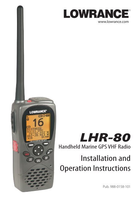
LHR-80<br />
Handheld <strong>Marine</strong> GPS VHF Radio<br />
Installation and<br />
Operation Instructions<br />
Pub. 988-0158-101
Copyright © 2008 Navico<br />
All rights reserved.<br />
Lowrance® is a registered trademark of Navico<br />
No part of this manual may be copied, reproduced, republished, transmitted or<br />
distributed for any purpose, without prior written consent of Lowrance Electronics.<br />
Any unauthorized commercial distribution of this manual is strictly<br />
prohibited.<br />
Lowrance Electronics may find it necessary to change or end policies, regulations,<br />
and special offers at any time. We reserve the right to do so without warning. All<br />
features and specifications are also subject to change without warning. All screens<br />
in this manual are simulated. LHR-80 VHF shown on cover. Other models covered<br />
in the manual are similar.<br />
In accordance with EU regulations, DSC is not available in Europe.<br />
For free owner’s manuals and the most current information on this product, its<br />
operation and accessories, visit our web site: www.lowrance.com<br />
Lowrance Electronics<br />
12000 E. Skelly Dr.<br />
Tulsa, OK USA 74128-2486<br />
Printed in China.<br />
Important safety information<br />
Please read carefully before installation and use.<br />
DANGER<br />
WARNING<br />
CAUTION<br />
CAUTION<br />
This is the safety alert symbol. It is used to alert you to potentially<br />
hazardous situations. Obey all safety messages that follow this<br />
symbol to avoid possible injury or death.<br />
WARNING indicates a potentially hazardous situation which, if not<br />
avoided, could result in death or serious injury<br />
CAUTION indicates a potentially hazardous situation which, if not<br />
avoided, could result in minor or moderate injury.<br />
CAUTION used without the safety alert symbol indicates a<br />
potentially hazardous situation which, if not avoided, may result in<br />
property damage.
Contents<br />
Safety and Operational Information.................................................................6<br />
Section 1 - General Information.........................................................................8<br />
Section 2 - Controls and Keys.............................................................................9<br />
2-1 Keys/Controls & Functions........................................................................................................... 10<br />
Section 3 - VHF Radio Operation......................................................................13<br />
3-1 Batteries and Charger ................................................................................................................... 13<br />
3-1-1 Installing the Battery Pack........................................................................................................................13<br />
3-1-2 Initial Charge....................................................................................................................................................13<br />
3-1-3 GPS Connector................................................................................................................................................14<br />
3-1-4 Mounting Battery Charger to flat surface......................................................................................15<br />
3-1-5 Mounting Battery Charger and bracket onto wall....................................................................15<br />
3-2 Installing the Belt Clip................................................................................................................... 16<br />
3-3 Installing and Removing the Antenna..................................................................................... 17<br />
3-4 Power On/Off.................................................................................................................................... 18<br />
3-5 Adjusting the Squelch level........................................................................................................ 18<br />
3-6 Volume control................................................................................................................................. 18<br />
3-7 Channel selection............................................................................................................................ 19<br />
3-8 Receiving and transmitting........................................................................................................ 19<br />
3-9 Dual Watch Operation................................................................................................................... 20<br />
3-10 3CH Operation (Favorite Channel)......................................................................................... 20<br />
3-10-1 Add a favorite channel for the first time......................................................................................20<br />
3-10-2 Modify or Delete favorite channel...................................................................................................20<br />
3-11 Scan Operation............................................................................................................................. 21<br />
3-12 Navigation Mode.......................................................................................................................... 21<br />
3-13 WP Select Mode............................................................................................................................. 22<br />
3-14 Plotter Mode ................................................................................................................................. 22<br />
3-15 GPS Satellite Mode...................................................................................................................... 23<br />
Section 4 - Advanced Operation......................................................................24<br />
4-1 Buddy List (Manage your buddy list. US only)...................................................................... 26<br />
4-1-1 Add a new buddy name...........................................................................................................................26<br />
4-1-2 Edit a buddy name.......................................................................................................................................27<br />
4-1-3 DELETE a buddy name...............................................................................................................................27<br />
4-2 Waypoint............................................................................................................................................. 28<br />
4-2-1 Add a new waypoint...................................................................................................................................28<br />
Lowrance - LHR-80 Installation and Operation Instructions 3
4-2-2 Edit a waypoint...............................................................................................................................................29<br />
4-2-3 Delete a waypoint.........................................................................................................................................30<br />
4-2-4 Set a route to a stored waypoint........................................................................................................30<br />
4-3 Backlight Adjustment................................................................................................................... 31<br />
4-4 Lamp Timer....................................................................................................................................... 31<br />
4-5 Contrast Adjustment..................................................................................................................... 31<br />
4-6 GPS/DATA .......................................................................................................................................... 32<br />
4-6-1 Manual (Manually Enter Your Position and UTC Time)...........................................................32<br />
4-6-2 Settings: LL Display (Show or hide your position)....................................................................33<br />
4-6-3 Settings: Time Display (Show or hide the time).........................................................................33<br />
4-6-4 Time Offset (Local time)............................................................................................................................34<br />
4-6-5 Settings: Time Format (12 or 24 hour clock).................................................................................35<br />
4-6-6 Settings: COG/SOG (Course & speed display options)...........................................................36<br />
4-6-7 GPS Alert.............................................................................................................................................................36<br />
4-6-8 Turn GPS ENABLE on/off...........................................................................................................................37<br />
4-6-9 Set Magnetic Variation (MAG VAR)......................................................................................................37<br />
4-7 Radio Setup....................................................................................................................................... 38<br />
4-7-1 UIC (US only).....................................................................................................................................................38<br />
4-7-2 Channel Name Editing...............................................................................................................................38<br />
4-7-3 Ring Volume Adjustment.........................................................................................................................39<br />
4-7-4 Beep Volume Adjustment........................................................................................................................39<br />
4-7-5 Select Unit (UNITS)........................................................................................................................................39<br />
4-7-6 Set the Priority Channel (WATCH MODE) (US only) .................................................................40<br />
4-7-7 Weather Alerts (WX ALERT) (US only)...............................................................................................40<br />
4-7-8 Set NMEA OUT (NMEA OUT)..................................................................................................................40<br />
4-8 DSC Setup (US only)...................................................................................................................... 41<br />
4-8-1 Enter or Check Your USER MMSI (USER MMSI)............................................................................41<br />
4-8-2 Maintain Groups ............................................................................................................................................42<br />
4-8-2-1 Enter your Groups........................................................................................................................... 42<br />
4-8-2-2 Edit user Groups............................................................................................................................... 43<br />
4-8-2-3 Delete a Group.................................................................................................................................. 43<br />
4-8-3 Response to Individual Calls (INDIV REPLY)...................................................................................44<br />
4-8-4 Enable DSC Functionality (DSC SELECT).........................................................................................44<br />
4-8-5 Response Type to LL Polling Calls (LL REPLY)...............................................................................44<br />
4-9 ATIS SETUP (EU only)..................................................................................................................... 45<br />
4-9-1 Enter or check your ATIS MMSI (ATIS MMSI)..................................................................................45<br />
4-9-2 Enable ATIS Functionality (ATIS SELECT).........................................................................................46<br />
4-10 Get Buddy ...................................................................................................................................... 46<br />
4-11 Track Log.......................................................................................................................................... 47<br />
4-12 Erase Track....................................................................................................................................... 47<br />
4-13 Reset (Reset to factory defaults).............................................................................................. 47<br />
4<br />
Lowrance - LHR-80 Installation and Operation Instructions
Section 5 - Sending and Receiving DSC Calls (US only)...................................48<br />
5-1 What is DSC?..................................................................................................................................... 48<br />
5-1-1 Maritime Mobile Service Identity........................................................................................................48<br />
5-1-2 How can I obtain a MMSI number?....................................................................................................48<br />
5-2 DSC Call Types.................................................................................................................................. 49<br />
5-2-1 Send an Individual call...............................................................................................................................50<br />
5-3 Send a Group Call............................................................................................................................ 51<br />
5-4 Send an All Ships call...................................................................................................................... 51<br />
5-5 Reply to a call in your Call Log................................................................................................... 52<br />
5-6 Reply to a call in your Distress Log............................................................................................ 53<br />
5-7 Reply to the Last Call..................................................................................................................... 54<br />
5-8 Request the LL position of a buddy (LL Request)............................................................... 55<br />
5-9 Track Your Buddy Request (TRACK BUDDY)........................................................................... 55<br />
5-9-1 Add or Delete a Buddy (TRACKLIST).................................................................................................55<br />
5-9-2 Select your TRACK BUDDY.......................................................................................................................56<br />
5-9-3 Set the time interval of tracking...........................................................................................................56<br />
5-9-4 Start Tracking ...................................................................................................................................................56<br />
5-10 Receive an All Ships call.............................................................................................................. 57<br />
5-11 Receive a Group call..................................................................................................................... 57<br />
5-12 Reply to an LL position request............................................................................................... 58<br />
5-12-1 Manually reply to an LL Request.......................................................................................................58<br />
5-12-2 Automatically reply to an LL position request..........................................................................58<br />
5-12-3 Do not reply to an LL position request.........................................................................................59<br />
5-13 Receive an individual call........................................................................................................... 59<br />
5-14 Receive a Polled Position Call................................................................................................... 59<br />
Section 6 - Distress Calls (US only)...................................................................60<br />
6-1 Send a Distress Call......................................................................................................................... 60<br />
6-2 Receive a Distress Call.................................................................................................................... 61<br />
6-3 Receive a Distress Relay Call........................................................................................................ 61<br />
6-4 Receive Distress Acknowledgement (DISTRESS ACK)....................................................... 62<br />
6-5 Relay a Distress Call from the Distress LOG (RELAY).......................................................... 62<br />
Appendix A - Technical Specifications............................................................64<br />
A-1 General:..................................................................................................................................................................64<br />
A-2 Receiver:.................................................................................................................................................................64<br />
A-3 Transmitter: .........................................................................................................................................................65<br />
A-4 GPS and Navigation:.......................................................................................................................................65<br />
Lowrance - LHR-80 Installation and Operation Instructions 5
Appendix B - Frequency Charts........................................................................66<br />
International <strong>Marine</strong> Channels...........................................................................................................................66<br />
Special Notes on International Channel Usage.......................................................................................67<br />
USA Channel Chart....................................................................................................................................................68<br />
Special Notes on USA Channel Usage ..........................................................................................................69<br />
CANADA Channel Chart.........................................................................................................................................70<br />
Special Notes on Canada Channel Usage...................................................................................................71<br />
WEATHER Channels...................................................................................................................................................72<br />
Appendix C - EU Inland Waterway Channels .................................................73<br />
Special Channels 2 ...................................................................................................................................................76<br />
Navico Full One-Year Lowrance VHF Warranty...............................................77<br />
How to Obtain Service......................................................................................78<br />
In the USA.................................................................................................................................................. 78<br />
In Canada................................................................................................................................................... 78<br />
Outside Canada and the USA............................................................................................................. 78<br />
Accessory Ordering Information for all countries..........................................79<br />
Shipping Information.......................................................................................79<br />
Safety and Operational Information<br />
CAUTION<br />
Due to European Union (EU) regulations, DSC is not available in the LHR-80E (EU) model.<br />
WARNING<br />
Never leave your radio in a closed car or trunk; the extremely high temperatures generated<br />
in hot weather can damage the electronics.<br />
6<br />
Lowrance - LHR-80 Installation and Operation Instructions
FCC Statement<br />
This device complies with part 15 of the FCC Rules. Operation is subject to the following<br />
two conditions: (1) This device may not cause harmful interference, and (2) this device<br />
must accept any interference received, including interference that may cause undesired<br />
operation.<br />
FCC regulations require that members of the general public should not be exposed to<br />
excessive levels of radio frequency radiation. To comply with the specified limits it is<br />
recommended that this radio is operated in such a manner as to limit transmission to<br />
no more than five minutes in any half hour period and that the antenna is kept at least 8<br />
inches from any part of the body during transmission.<br />
CAUTION: Changes or modifications not expressly approved by the manufacturer could<br />
void the user’s authority to operate the equipment.<br />
1.<br />
2.<br />
3.<br />
4.<br />
IMPORTANT<br />
DSC functions will not operate until you have entered your user MMSI.<br />
The radio channels installed into the radio may vary from country to country,<br />
depending upon the model and government or national communications authority<br />
regulations.<br />
Lowrance recommends that you check the radio operating licensing requirements of<br />
your country before using the radio. The operator is solely responsible for observing<br />
proper radio installation and usage practices.<br />
This radio is designed to generate a digital maritime distress call to facilitate search<br />
and rescue. To be effective as a safety device, this radio must be used only within the<br />
geographic range of a shore-based VHF marine Channel 70 distress and safety watch<br />
system. The geographic range may vary but under normal conditions is approximately<br />
20 nautical miles.<br />
It is the owner’s sole responsibility to install and use the instrument in such a manner that will<br />
not cause accidents, personal injury or property damage.<br />
Lowrance disclaims all liability for any use of this product in a way that may cause accidents,<br />
damage or that may violate the law.<br />
Governing Language: This statement, any instruction manuals, user guides and other information<br />
relating to the product (Documentation) may be translated to, or has been translated<br />
from, another language (Translation). In the event of any conflict between any Translation<br />
of Documentation, the English language version of the Documentation will be the official<br />
version of the Documentation.<br />
This manual represents the LHR-80 radio at the time of printing. Lowrance reserves the right<br />
to make changes to specifications without notice.<br />
Lowrance - LHR-80 Installation and Operation Instructions 7
Section 1 - General Information<br />
Congratulations on your purchase of this handheld VHF marine radio LHR-80, designed and<br />
built using superior technology and craftsmanship. It provides the following useful features:<br />
• Adjustable contrast settings for the LCD<br />
• Adjustable keypad backlighting for easy night time use<br />
• Waterproof and submersible to comply with JIS-7<br />
• GPS latitude and longitude (LL) and time display<br />
• Built-in GPS sensor<br />
• Choice of High or Low (5W or 1W) transmission power<br />
• Special CH16 key for quick access to the priority (international distress) channel<br />
• Special 3CH key to select your three favorite channels<br />
• Flexible dual watch facility<br />
• DSC (Digital Selective Calling) capability that meets USCG SC101 Standards (US<br />
only) DISTRESS call button to automatically transmit the MMSI and position until an<br />
acknowledgement is received (US only)<br />
• Easy access to a buddy list of up to 20 favorite people (US only)<br />
• LL position polling information<br />
• Buddy tracking capacity<br />
• Weather alert facility (US only)<br />
• ATIS facility for inland waterways (Europe only)<br />
8<br />
Lowrance - LHR-80 Installation and Operation Instructions
Section 2 - Controls and Keys<br />
VHF Antenna<br />
POWER/KEYLOCK<br />
GPS Antenna<br />
Signal strength<br />
Status: T or R<br />
PTT<br />
Working mode<br />
channel name<br />
Time COG/SOG<br />
Latitude<br />
Longitude<br />
Left Soft Key<br />
DISTRESS<br />
(US only)<br />
LHR-80 MARINE VHF/GPS<br />
R<br />
Tx Power: HI or LO<br />
Low battery indicator<br />
Speaker/Mic jack<br />
Channel<br />
Favorite channels:<br />
1, 2 or 3<br />
Vol + and Vol -<br />
Right Soft Key<br />
CH /<br />
SQ /<br />
16 (US)<br />
16 (EU)<br />
HI/LO<br />
HI/LO/GPS<br />
GO/MOB<br />
WX/NAV<br />
CALL/MENU<br />
WATERPROOF<br />
Mic<br />
Speaker<br />
Lowrance - LHR-80 Installation and Operation Instructions 9
10<br />
2-1 Keys/Controls & Functions<br />
PWR On/Off & KEYLOCK<br />
To turn the unit on and off, press and hold down PWR /<br />
and release.<br />
Lowrance - LHR-80 Installation and Operation Instructions<br />
(red key) for more than 2 seconds<br />
The keylock, locks and unlocks keypad. Press PWR / (red key) for 1 second and release. A<br />
key icon will appear on screen to indicate whether keylock is on or off.<br />
VOL /<br />
Volume Adjustment. Press to increase or decrease until a comfortable volume is reached.<br />
SQL /<br />
Squelch or Threshold Level. Sets the threshold level for the minimum receiver signal. 16 steps<br />
available.<br />
16/9<br />
Priority Channel. Press to cancel all other modes and to tune into the priority channel. Press<br />
again to return to your original channel. To make Channel 09 the default instead, hold down<br />
16/9 until a beep sounds and 09 is displayed (US only).<br />
16 Priority Channel. Press to cancel all other modes and to turn into the priority channel. Press<br />
again to return to your original channel (EU only).<br />
Left Soft Key (3CH/ ESC)<br />
Three Favorite Channels. Press to toggle between your favorite channels. The , , or<br />
symbol appears on the LCD to show which favorite channel is selected.<br />
If you want to scan all three favorite channels, press 3CH, then immediately press and hold<br />
SCAN.<br />
To add a favorite channel for the first time, select that channel then hold 3CH to store it in the<br />
CH1 location. Repeat the procedure to store two more favorite channels in the CH2 and CH3<br />
locations respectively.<br />
If you try and add another favorite channel it will overwrite the existing CH3. CH1 and CH2<br />
will remain unless you delete them.<br />
To delete a favorite channel, select that channel then hold down 3CH until a dialog box<br />
appears to prompt the deletion.<br />
Escape. Use ESC when navigating menus to clear incorrect entries, to exit from a menu without<br />
saving changes and to back up to the previous screen.<br />
Right Soft Key (SCAN/ ENTER)<br />
Scan. Quickly press and release for Dual Watch - scan between your current channel and the<br />
priority channel in DUAL mode.
Press and hold down SCAN for more than 2 seconds to enter ALL SCAN mode where the<br />
priority channel is checked every 1.5 seconds.<br />
When a signal is received, scanning stops at that channel and “R” appears on the screen. If the<br />
signal ceases for more than 5 seconds, the scan restarts.<br />
In ALL SCAN mode, when a signal is received, holding down left- key for more than 2 seconds<br />
makes appear on the screen. This “always busy” channel will not have been skipped in the<br />
next scan period. If this channel needs recover, holding down left-key once again for more<br />
than 2 seconds makes disappear. The skip function is cancelled accordingly. Besides, it is<br />
impossible to skip over the priority channel.<br />
Enter. Use ENTER when navigating menus, to confirm entries and edits.<br />
CH /<br />
Channel Select. The current channel is shown on the screen in BIG digits with the channel<br />
description information below the channel number.<br />
Press CH / to step through the available channels one at a time, or hold down to scroll<br />
quickly through all the available channels. See Appendix B for a listing of channel charts.<br />
Alphanumeric Entry. This key can also be used for menu selection and alphanumeric entry.<br />
Press CH / to scroll the cursor up or down menu options when navigating menus.<br />
When editing an item that contains only numbers, press - CH to count through the numbers<br />
or hold down to scroll through quickly.<br />
To enter a character, press CH to step through the alphabet or hold down to scroll through<br />
quickly.<br />
HI/LO/<br />
Transmission Power. High (HI) 5W or Low (LO) 1W. Press to toggle between high or low<br />
transmission powers for the entire channel bank. The or selection is shown on the LCD<br />
screen.<br />
Some channels allow only low power transmissions. Error beeps will sound if the power<br />
transmission setting is incorrect.<br />
Some channels allow only low power transmissions initially, but can be changed to high<br />
power by holding down HI/LO and PTT all at the same time. See Appendix B for a complete<br />
listing of channel charts.<br />
hold down and enter GPS Satellite mode.<br />
WX/NAV<br />
Quickly press to access WX channel (US/Canada only).<br />
Lowrance - LHR-80 Installation and Operation Instructions 11
The channel is used mostly for weather. Press again to return to your previous mode. Hold<br />
down WX/NAV for more than 3 seconds to enter Navigation mode. Bearing, Distance and<br />
cross track error from the last selected waypoint will display on the screen. If no WP is set, it<br />
will appear “NO ACTIVE ROUTE!!” prompt.<br />
NAV. Press NAV to enter Navigation mode. Bearing, Distance and Cross Track error from the<br />
Waypoint will display on screen. If no WP is set, it will appear “NO ACTIVE ROUTE!!” prompt.<br />
GO/MOB<br />
Press GO / MOB if you are navigating to waypoint and want to reset the XTE (cross track error)<br />
as shown on the screen.<br />
If someone falls overboard, hold down GO / MOB for about 3 seconds to mark the position.<br />
The latitude and longitude of the Man Overboard position is shown on the screen and is<br />
automatically set as the destination waypoint.<br />
PTT<br />
Push To Talk. Push to start the transmitting<br />
CALL/MENU<br />
Quickly press the CALL/MENU key to access the DSC Call menu. The call mode is used for<br />
making DSC calls. Hold down the Key more than 3 seconds to access the Menu Setup mode<br />
and to customize your VHF radio. US only<br />
MENU. Quickly press the MENU key to access the Menu setup mode and to customize your<br />
VHF radio (EU only).<br />
Please refer to the following sections for more details.<br />
CAUTION<br />
BATTERY CAUTION: This device uses a Lithion Ion battery - please observe the following<br />
cautions.<br />
• Do not disassemble.<br />
• Do not incinerate or expose to fire.<br />
• Dispose of used batteries according to local codes and requirements.<br />
12<br />
Lowrance - LHR-80 Installation and Operation Instructions
Section 3 - VHF Radio Operation<br />
3-1 Batteries and Charger<br />
The radio is shipped with a sealed Li-Polymer battery pack that is rechargeable.<br />
WARNING<br />
The charger provided for this radio is only to be used to charge the battery pack provided.<br />
DO NOT charge any other type of batteries in the charger as fire, explosion or battery<br />
damage could occur. Avoiding extreme room temperature will also help prolong the life<br />
of the battery pack for the radio.<br />
3-1-1 Installing the Battery Pack<br />
1. Position the battery pack to line up the three external alignment tabs to the alignment<br />
slots in the radio.<br />
2. Engage the battery pack into the radio until battery pack is fully seated against the radio<br />
housing.<br />
3.<br />
Pivot the locking tab up until it snaps into place on the back of the battery pack.<br />
3-1-2 Initial Charge<br />
You can either charge the Li-Polymer battery<br />
pack when it is attached to the radio or separated:<br />
Lowrance - LHR-80 Installation and Operation Instructions 13
1.<br />
2.<br />
3.<br />
4.<br />
5.<br />
Plug in the AC/DC wall charger- check the voltage is correct for your wall charger.<br />
Connect the charging wire into the charging socket on the cradle charger.<br />
Insert the entire radio or the separated battery pack into the cradle charger. The metal<br />
charge contacts on the radio will contact the mating prongs in the charger to transfer<br />
the charging current.<br />
Observe that the red light on the front of the charger glows to indicate that the battery<br />
pack is properly seated and the charger is operating.<br />
Allow the battery to charge for about 2.5 to 3 hours before use. The light will change<br />
back to green when the battery is fully charged.<br />
CAUTION<br />
To maximise battery life: remove the battery from the charger after approximately 3.5<br />
hours. Overcharging batteries may result in damage to both the battery pack and radio.<br />
3-1-3 GPS Connector<br />
NMEA(+)(RED)<br />
NMEA(-)(BLACK)<br />
GPS NAVIGATION RECEIVER<br />
14<br />
Lowrance - LHR-80 Installation and Operation Instructions
This radio supports NMEA0183 for outputting the GPS signal. You can use the GPS connector<br />
to connect the radio and some GPS navigation receiver, such as chart plotter.<br />
1.<br />
2.<br />
Insert the GPS connector cord into the NMEA socket of the cradle charger.<br />
Connect the chart plotter to the VHF using the following wiring code:<br />
Wire Color<br />
Red<br />
Black<br />
Function<br />
NMEA OUT(+)<br />
NMEA OUT(-)<br />
3-1-4 Mounting Battery Charger to flat surface<br />
You can mount the battery charger straight onto solid surface. Make sure that the surface can<br />
be penetrated and is strong enough to hold permanantly in place.<br />
3-1-5 Mounting Battery Charger and bracket onto wall<br />
You can also mount the battery charger onto wall by using the provided bracket and screws.<br />
1. Mount the bracket as indicated in the diagram.<br />
2. Attach the battery charger to the bracket using the screws provided.<br />
Lowrance - LHR-80 Installation and Operation Instructions 15
To remove the battery from the radio:<br />
1. Slide the two levers (simultaneously) in a downward motion.<br />
2. Remove battery.<br />
3-2 Installing the Belt Clip<br />
1.<br />
Slide the clip (2) into the recess on the back of the radio battery.<br />
2.<br />
The belt clip supplied with your radio allows you to attach the radio to your belt. To<br />
install the belt clip: slide the belt clip to the back of your radio, make sure that the fitting<br />
Groove is aligned.<br />
16<br />
Lowrance - LHR-80 Installation and Operation Instructions
3-3 Installing and Removing the Antenna<br />
Make sure that the flexible antenna is attached to the radio. Ensure that the radio is turned<br />
OFF anytime that the antenna is not connected.<br />
Installing the antenna:<br />
1. Screw the antenna in a clockwise motion until it is securely locked into place.<br />
Removing the antenna:<br />
2. Unscrew the antenna in a anti-clockwise motion until it is removed (as illustrated below).<br />
Note: Do not operate the radio or press PTT key without the antenna being installed.<br />
Lowrance - LHR-80 Installation and Operation Instructions 17
3-4 Power On/Off<br />
You can turn on the unit by pressing PWR/ switch (on the top side of radio) until the screen<br />
and backlight are on. You can also adjust the volume to a comfortable level, by pressing the<br />
VOL / keys on the side of unit.<br />
Note: Press the PWR/<br />
3-5 Adjusting the Squelch level<br />
key at any time will turn the display backlight on.<br />
The SQUELCH control enables you to set the levels of your desired signal. It determines how<br />
strong your signal can be before you can hear it, before it “breaks squelch.” It aims to keep any<br />
static, unwanted, weak or distant signals from interrupting your conversations.<br />
There are 16 signals to choose from when adjusting the squelch level. To increase the levels,<br />
raise the “Squelch Gate” higher so that only stronger signals can get through. Level “0” for<br />
instance, means that there is no “Squelch Gate” and everything will get through.<br />
To adjust the squelch level, press SQL / accordingly.<br />
3-6 Volume control<br />
Press VOL / to adjust the volume level. A volume sub-menu will appear when pressed. It<br />
times-out after 5 seconds.<br />
18<br />
Lowrance - LHR-80 Installation and Operation Instructions
3-7 Channel selection<br />
To manually select a channel, press CH to increase, or press CH to decrease the channel<br />
number. Communication channels are located on channel 01-28 and 60-88. For more<br />
detailed channel chart information, refer to Appendix B.<br />
16/9 (Priority channel)<br />
LVR-80 (US only).<br />
1.<br />
2.<br />
3.<br />
Press to cancel all other modes and tune into the priority channel on Hi power.<br />
Press again to return to your original channel.<br />
Channel 16 is the default. To make Channel 09 the default instead, hold down 16/9 until<br />
a beep sounds and 09 is displayed.<br />
16 (Priority channel)<br />
LVR-80 (EU only).<br />
1.<br />
2.<br />
Press to cancel all other modes and tune into the priority channel on Hi power.<br />
Press again to return to original channel.<br />
3-8 Receiving and transmitting<br />
CAUTION<br />
Transmitting without an antenna may damage the radio.<br />
1.<br />
2.<br />
3.<br />
To turn power on, press the PWR key for more than 2 seconds<br />
Adjust for comfortable volume level. ( The squelch level temporarily set to “0”)<br />
Set the suitable Squelch level to mute noise if necessary.<br />
4. Press CH / to select the desired channel.<br />
5.<br />
When receiving a signal,<br />
appears on screen and audio is emitted from the speaker.<br />
Further volume adjustment may be needed to get your desired setting.<br />
Press HI/LO to select the output power.<br />
Choose low power to conserve battery power, or choose high power for longer distance<br />
communications.<br />
6. Press and hold “PTT” to transmit, then speak into the microphone, while appears on<br />
the screen.<br />
7.<br />
Release PTT, to receive conversation.<br />
Lowrance - LHR-80 Installation and Operation Instructions 19
Note: Some channels are for low power only. Channel 70 cannot be used for<br />
transmission.<br />
For clear and audible transmission:<br />
• Pause for a few seconds after pressing PTT.<br />
• Hold the microphone 5 to 10 cm (2 to 4 inches) away from your mouth and speak at a<br />
normal volume.<br />
3-9 Dual Watch Operation<br />
Dual watch monitors channel 16 while receiving another channel. To activate this, you must:<br />
1.<br />
Select the desired operating channel (e.g. CH88A).<br />
2. Push the SCAN key repeatedly until appears on screen<br />
3. To cancel dual watch, press SCAN (once) until disappears.<br />
If a signal is received on channel 16, dual watch pauses on channel 16 until the signal<br />
disappears.<br />
To transmit on the selected channel during dual watch, press and hold PTT.<br />
3-10 3CH Operation (Favorite Channel)<br />
You can instantly access the three most frequently used channels by 3CH mode, Three<br />
Favorite Channels. Press to toggle between your favorite channels. The , , or symbols<br />
appear on the LCD to show which of your favorite channel is selected.<br />
3-10-1 Add a favorite channel for the first time<br />
1. Select the desired channel, then hold 3CH to store it. The CH1 symbol appears on the<br />
screen.<br />
2.<br />
Repeat the procedure to store two more favorite channels in the CH2 and CH3<br />
locations.<br />
3-10-2 Modify or Delete favorite channel<br />
If you try and add another favorite channel it will overwrite the existing CH3. But CH1 and<br />
CH2 will remain unless you delete them.<br />
To delete a favorite channel:<br />
• Select that channel, then hold down 3CH until a dialog box appears to prompt the<br />
deletion.<br />
20<br />
Lowrance - LHR-80 Installation and Operation Instructions
3-11 Scan Operation<br />
Scanning is an effective way to locate signals quickly over a wide frequency range.<br />
All Scan<br />
All channels in the set are scanned sequentially, in repeated cycles (CH16 is checked every 1.5<br />
seconds).<br />
01 02 03 16 04 88<br />
3CH Scan<br />
Press and hold down the SCAN key in the 3CH mode, you will then enter a 3CH SCAN mode.<br />
However, only the 3CH and CH16 will be scanned.<br />
01 15 18 16 01 18<br />
3-12 Navigation Mode<br />
Press and hold down NAV key, (US only), or just press the NAV key (EU only) to enter the<br />
Navigation Mode. It will display: Bearing, Distance and cross track error from the last selected<br />
waypoint.<br />
If no WP is set, ‘NO ACTIVE ROUTE!!’ will appear to prompt you that no WP is selected.<br />
During Nav Mode:<br />
• PTT – return to normal mode and TX.<br />
• 16/9 – return to normal mode and go to 16/9<br />
Lowrance - LHR-80 Installation and Operation Instructions 21
• NAV – return to normal mode<br />
• GO – Reset the cross track error (XTE)<br />
• SQL – Go to WP select Mode<br />
• SQL – Go to Plotter Mode<br />
• Other key – error beep<br />
3-13 WP Select Mode<br />
WP LIST 13<br />
CAMP 1 MOB 1<br />
CAMP 2 MOB 2<br />
CAMP 3 MOB 3<br />
DOCK 1 PARK 1<br />
DOCK 2 PARK 2<br />
ESC<br />
ENTER<br />
• CH / – Page up down the list;<br />
• SQL - Go to Plotter Mode;<br />
• SQL - Returns to Navigation Mode<br />
Note: During WP Select Mode, press ENTER right-key to flash the first WP, then press<br />
CH / to select next WP, press ENTER right-key again to set the WP as your next<br />
destination and enter navigation mode.<br />
3-14 Plotter Mode<br />
During plotter Mode:<br />
•<br />
Soft Key<br />
It will zoom in/out the circle to see more/less area.<br />
• SQL<br />
Go to Navigation Mode<br />
22<br />
Lowrance - LHR-80 Installation and Operation Instructions
• SQL<br />
Go to WP select Mode<br />
•<br />
•<br />
•<br />
•<br />
PTT<br />
Return to normal mode and TX.<br />
16/9 Return to normal mode and go to 16/9<br />
NAV<br />
Other key<br />
Go to normal mode<br />
Error beep<br />
To avoid screen clutter, a maximum of 5 waypoint icons closest to you plus the active waypoint<br />
are shown.<br />
3-15 GPS Satellite Mode<br />
Press and hold the HI/LO/<br />
During GPS satellite mode:<br />
•<br />
•<br />
PTT<br />
key to enter GPS satellite mode.<br />
Return to normal mode and TX.<br />
16/9 (16) Return to normal model and go to 16/9<br />
• Return to normal mode<br />
•<br />
Left soft-key<br />
• Other key<br />
Return to normal mode<br />
Error Beep<br />
Lowrance - LHR-80 Installation and Operation Instructions 23
Section 4 - Advanced Operation<br />
How to Display and Navigate Menus<br />
1.<br />
Hold down CALL / MENU key to enter in menu (US only); or press MENU key to enter<br />
setup mode (EU only).<br />
2. Press CH / to scroll up and down the menu until the cursor is positioned at the<br />
desired items. Press soft-key ENTER to enter into the items.<br />
3.<br />
4.<br />
Press soft-key ENTER to confirm changes. Otherwise, press soft-key ESC to ignore.<br />
Press soft-key ESC to go back or exit. Any changes are activated as soon as you enter/<br />
exit the screen.<br />
How to Enter Alphanumeric and Alphabet Data<br />
Use the CH / key to enter characters.<br />
1. Press to enter and count through numbers and letters, and hold down to select the<br />
desired character.<br />
2. Press to go through letters of the alphabet, and hold down to select the desired<br />
character.<br />
3.<br />
Press ENTER to confirm.<br />
The following options are available through MENU:<br />
MENU<br />
• UIC (US only)<br />
• Waypoint<br />
• Backlight<br />
• Lamp<br />
• Buddy List<br />
(US only)<br />
• Contrast<br />
• GPS/Data<br />
• RADIO SETUP<br />
• DSC Setup<br />
(US only)<br />
• ATIS SETUP<br />
(EU only)<br />
• GET BUDDY<br />
(US only)<br />
• Track Log<br />
• Erase Track<br />
• RESET<br />
• MANUAL<br />
• SETTING<br />
• ATIS MMSI<br />
(EU only)<br />
• ATIS Select<br />
(EU only)<br />
• CH NAME<br />
• RING VOLUME<br />
• KEY BEEP<br />
• UNITS<br />
• WATCH MODE<br />
(US only)<br />
• WX ALERT<br />
(US only)<br />
• NMEA OUT<br />
• User MMSI<br />
(US only)<br />
• Group MMSI<br />
(US only)<br />
• Idiv Reply<br />
(US only)<br />
• DSC SELECT<br />
(US only)<br />
• LL Reply<br />
(US only)<br />
24<br />
Lowrance - LHR-80 Installation and Operation Instructions
Hold down the CALL/ MENU key to enter radio set-up mode. This allows the following functions<br />
to be accessed. Scroll down the list and press ENTER. To exit the Menu or sub-menu<br />
modes press 16 or EXIT.<br />
WAYPOINT<br />
BACKLIGHT<br />
LAMP<br />
BUDDY LIST<br />
CONTRAST<br />
GPS/DATA<br />
RADIO SETUP<br />
DSC SETUP<br />
ATIS SETUP<br />
GET BUDDY<br />
TRACK LOG<br />
ERASE TRACE<br />
Selects the WP List Entry to enter names and LL positions for a WP.<br />
Up to 500 WP can be stored.<br />
Sets the backlight level: 8 levels.<br />
Sets the backlight lamp time out.<br />
Selects the Buddy List Entry to enter names and MMSI’s for<br />
regularly called DSC stations. Up to 20 names can be stored (US only).<br />
Selects display contrast setting: 1-4 levels.<br />
Select to change the following GPS/DATA settings: Time Offset, Format,<br />
Display, LL Display, COG/SOG, GPS Alert, GPS Enabled.<br />
Select to change the following radio settings: Band, CH Name, Ring Tone<br />
Volume, Beep Volume, Units, Watch mode, WX alert<br />
Select to change the following DSC settings: User MMSI enter, Group<br />
MMSI, INDIV RELAY AND LL Relay (US only).<br />
Select to change the following ATIS settings: ATIS MMSI Enter, ATIS<br />
Select. (EU Only).<br />
Enable or disable Buddy Data and Auto Function.<br />
Set the distance interval for recording the track points.<br />
Erase track history points.<br />
RESET<br />
Set-up Menu Navigation<br />
To access the Menu Mode:<br />
•<br />
1.<br />
Reset to factory settings.<br />
Press and hold CALL/MENU key, or press MENU key. Text area displays the Set-Up Menu<br />
list.<br />
Press the 16 or ESC soft-key to exit from the menu.<br />
2. Press the CH / to select the Item within the Set-Up Menu list. To confirm a selected<br />
item, push ENTER soft-key.<br />
3. Or use CH / knob to enter alphanumeric or alphabet data.<br />
4.<br />
5.<br />
To confirm a selected item, push ENTER soft-key.<br />
Turn unit off. All changes are saved to EEPROM.<br />
Lowrance - LHR-80 Installation and Operation Instructions 25
4-1 Buddy List (Manage your buddy list. US only)<br />
You can use the buddy list to store names and associated MMSIs of 20 DSC stations that you<br />
call frequently. Buddy names are stored in the order of entry, with the most recent entry first.<br />
The following sections demonstrates how to use BUDDY LIST, these include: to add, edit, and<br />
delete entries.<br />
4-1-1 Add a new buddy name<br />
You can enter up to 20 buddy names. When your BUDDY LIST is full, you cannot make a new<br />
entry until you have deleted an existing entry.<br />
• Each buddy name can have a maximum of 11 alphanumeric characters.<br />
• The most recent buddy name entered is shown at the top of your buddy list.<br />
MENU select<br />
lamp<br />
> BUDDY LIST<br />
contrast<br />
buddy list<br />
>manual new<br />
ENTER NAME<br />
_ _ _ _ _ _ _ _ _<br />
ENTER MMSI<br />
_ _ _ _ _ _ _ _ _ _ _<br />
ENTER NAME<br />
STARFISH 2<br />
ENTER MMSI_<br />
_ _ _ _ _ _ _ _ _ _ _<br />
ENTER NAME<br />
STARFISH 2<br />
ENTER MMSI<br />
0 _ _ _ _ _ _ _ __<br />
ENTER NAME<br />
STARFISH 2<br />
ENTER MMSI<br />
123456789<br />
STARFISH 2<br />
123456789<br />
>STORE<br />
CANCEL<br />
>MANUAL NEW<br />
STARFISH 2<br />
SEA ROSE<br />
MERMAID<br />
1.<br />
2.<br />
3.<br />
Hold down CALL/MENU for 3 seconds.<br />
Select BUDDY LIST then press ENTER.<br />
The cursor is at . Push ENTER.<br />
4. Use the CH / to enter the new buddy name one character at a time. Then press<br />
ENTER until the cursor moves to the MMSI entry line.<br />
5. Use CH / to enter the 9-digit MMSI that is associated with that buddy name, one<br />
number at a time, then press ENTER.<br />
6.<br />
After you enter the last digit of the MMSI, a new screen appears automatically to show<br />
the new buddy name and MMSI. Check that it is correct; and then push ENTER to save<br />
the new entry. (If it is not correct, select ESC).<br />
26<br />
Lowrance - LHR-80 Installation and Operation Instructions
4-1-2 Edit a buddy name<br />
MENU select<br />
Backlight<br />
Lamp<br />
>Buddylist<br />
BUDDY LIST<br />
MENU SELECT<br />
>SEA ROSE<br />
MERMAID<br />
SEA ROSE<br />
>EDIT<br />
DELETE<br />
edit name<br />
SEA ROSE _ _ _<br />
edit MMSI<br />
123456789<br />
edit NAME<br />
SEA ROSE<br />
edit MMSI<br />
123456789<br />
edit NAME<br />
SEA ROSE<br />
edit MMSI<br />
123456798<br />
SEA ROSE<br />
123456798<br />
>Store<br />
CANCEL<br />
1.<br />
2.<br />
3.<br />
4.<br />
5.<br />
Press and hold down CALL/MENU for about 3 seconds.<br />
Select BUDDY LIST then press ENTER.<br />
Scroll down to the entry you want to edit then press ENTER .<br />
The buddy name is displayed and the cursor is positioned at EDIT. Press ENTER<br />
The buddy name and MMSI are displayed. The cursor is at the first character of the<br />
name.<br />
6. Use CH / to change the first character of the buddy name then press ENTER, or just<br />
press ENTER to skip to the next character. Repeat if necessary. When you reach the last<br />
character of the buddy name, make any changes if needed, then press ENTER to move<br />
the cursor to the MMSI.<br />
Note: If you do not want to change the buddy name, just press ENTER repeatedly until<br />
the cursor moves to the MMSI line.<br />
7. To change the MMSI, use CH / to change the first number or press ENTER to skip to<br />
the next number. Repeat if necessary. When you reach the last number, press ENTER to<br />
display the SAVE screen.<br />
Note: If you do not want to change the MMSI, press ENTER repeatedly until the SAVE screen<br />
appears.<br />
8.<br />
Press ENTER to save the edits or CANCEL to keep the original entry.<br />
4-1-3 DELETE a buddy name<br />
menu SELECT<br />
BACKLIGHT<br />
LAMP<br />
> BUDDY LIST<br />
bUDDY LIST<br />
MANUAL NEW<br />
>SEA ROSE<br />
MERMAID<br />
SEA ROSE<br />
>EDIT<br />
DELETE<br />
DELETE BUDDY<br />
SEA ROSE<br />
>YES<br />
NO<br />
Lowrance - LHR-80 Installation and Operation Instructions 27
1.<br />
2.<br />
3.<br />
4.<br />
5.<br />
Hold down CALL MENU for about 3 seconds.<br />
Select BUDDY LIST. Press ENTER to display the list of buddy names.<br />
Scroll down to the buddy name you want to delete then press ENTER.<br />
Select DELETE then select YES.<br />
The buddy name is deleted and the revised buddy list is displayed.<br />
4-2 Waypoint<br />
You can store up to 500 waypoints and their LL positions. When your WAYPOINT LIST is full,<br />
you cannot make a new entry until you have deleted an existing one.<br />
• Each waypoint name can have a maximum of 6 alphanumeric characters.<br />
• The most recent waypoint name will be displayed at the top of your waypoint list.<br />
4-2-1 Add a new waypoint<br />
WP list<br />
>new wp<br />
fish1<br />
ENTER WP<br />
_ _ _ _ __ _ _<br />
_° _ . _ _ _’ N<br />
_ _° _ . _ _<br />
ENTER WP<br />
moor 1<br />
_° _ . _ _ _N<br />
_ _° _ . _ _ _W<br />
ENTER WP<br />
moor 1<br />
12° 32.233’N<br />
132°45.651’W<br />
SAVE<br />
MOOR 1<br />
>YES<br />
NO<br />
1.<br />
2.<br />
3.<br />
Hold down CALL MENU for 3 seconds (US ONLY); or press MENU key (EU only).<br />
The cursor is at WAYPOINT, press ENTER.<br />
Select WP LIST, and then NEW WP.<br />
4. Use the CH / to enter the new waypoint name, one alphanumeric character at a<br />
time. Select one waypoint symbol (there are 20 icons available); and then press ENTER<br />
until the cursor moves to the latitude line.<br />
5. Use the CH / to enter the latitude of the waypoint, one number at a time; then press<br />
ENTER. The cursor moves to the longitude.<br />
6. Use the CH / to enter the longitude waypoint, one number at a time, then press<br />
ENTER.<br />
7.<br />
A new screen appears automatically to show the new waypoint details. If they are<br />
correct, press ENTER to STORE the new waypoint. (If they are not correct, select ESC).<br />
28<br />
Lowrance - LHR-80 Installation and Operation Instructions
4-2-2 Edit a waypoint<br />
MENU SELECT<br />
>WAYPOINT<br />
BACKLIGHT<br />
LAMP<br />
WAYPOINT<br />
>WP LIST<br />
WP LIST<br />
NEW WP<br />
FISH 1<br />
> FISH 2<br />
WP EDIT<br />
fISH 2<br />
12 0 32.2332’N<br />
132 0 45.6512’W<br />
WP EDIT<br />
MOOR 1<br />
12 0 32.2332’N<br />
132 0 45.6512’W<br />
SAVE<br />
MOOR1<br />
>YES<br />
NO<br />
1.<br />
2.<br />
3.<br />
4.<br />
5.<br />
Hold down CALL MENU (US only); or press MENU (EU only).<br />
The cursor is at WAYPOINT. Press ENTER.<br />
Select WP LIST, then push ENTER, the cursor is at new WP. Scroll down to the waypoint<br />
you want to edit then push ENTER.<br />
Select WP EDIT and press ENTER.<br />
The waypoint details are displayed and the cursor is positioned at the first character of<br />
the name.<br />
6. Use the CH / to change the first character of the waypoint name then press ENTER,<br />
or just press ENTER to skip to the next character.<br />
When you reach the last character of the waypoint name, make any changes if necessary,<br />
then press ENTER to move the cursor to the waypoint icon.<br />
Note: If you do not want to change the waypoint name waypoint icon, press ENTER repeatedly<br />
until the cursor moves to the latitude.<br />
To change the waypoint icon, use the CH / to change the icon or press ENTER to skip to<br />
latitude. To change latitude, use the CH / to change the first digit or press ENTER to skip<br />
to the next digit. Repeat if necessary. When you reach the last digit, push ENTER to move the<br />
cursor to longitude.<br />
Note: If you do not want to change the latitude, press ENTER repeatedly until the cursor<br />
moves to the longitude.<br />
1.<br />
2.<br />
Repeat the previous step to change or press ENTER to continue.<br />
A new screen appears. Press ENTER if you want to STORE the new waypoint. If you want<br />
to keep the original entry, move the cursor to NO then press ENTER.<br />
Lowrance - LHR-80 Installation and Operation Instructions 29
4-2-3 Delete a waypoint<br />
menu select<br />
>waypoint<br />
backlight<br />
lamp<br />
waypoint<br />
>wp list<br />
NEAREST Wp<br />
TEMP<br />
wp list<br />
new wp<br />
fish 1<br />
>fish 2<br />
fish 2<br />
go<br />
wp edit<br />
>delete<br />
delete<br />
fish 2<br />
>yes<br />
no<br />
wp list<br />
new wp<br />
fish 1<br />
>home<br />
Hold down CALL MENU for about 3 seconds (US only); or press menu (EU only).<br />
1. The cursor is at WAYPOINT, press ENTER.<br />
2. Select WP list and press ENTER. The cursor is at new WP, scroll down to the waypoint you<br />
want to delete, then press ENTER.<br />
3. The cursor is at GO. Move the cursor to delete and push ENTER.<br />
4. The waypoint is deleted immediately and the revised waypoint list is displayed.<br />
4-2-4 Set a route to a stored waypoint<br />
menu select<br />
>waypoint<br />
backlight<br />
lamp<br />
waypoint<br />
>wp list<br />
nearest wp<br />
temp<br />
wp list<br />
new wp<br />
fish 1<br />
>home<br />
HOME<br />
>GO<br />
WP EDIT<br />
DELETE<br />
go<br />
home<br />
>yes<br />
no<br />
1.<br />
2.<br />
3.<br />
4.<br />
Hold down CALL/MENU for about 3 seconds (US only); or press MENU (EU only).<br />
The cursor is at WAYPOINT. Press ENTER.<br />
The cursor is at WP list, press ENTER. The cursor is at new WP, scroll down to the<br />
waypoint to use as the route then press ENTER.<br />
The cursor is at GO and push ENTER and enter the navigation mode. The waypoint is set<br />
as your next destination.<br />
30<br />
Lowrance - LHR-80 Installation and Operation Instructions
1.<br />
4-3 Backlight Adjustment<br />
Select BACKLIGHT and press ENTER. There are 8 contrast levels.<br />
2. SQ / to adjust the setting. Press ENTER to confirm the setting and return to the<br />
MENU SELECT.<br />
MENU SELECT<br />
WAYPOINT<br />
>BACKLIGHT<br />
LAMP<br />
Backlight<br />
LO<br />
HI<br />
1.<br />
4-4 Lamp Timer<br />
Select LAMP and press ENTER. There are 4 timer settings: Always on, 5s, 15s, 30s<br />
(default).<br />
2. Press CH / to adjust the setting. Press ENTER to confirm the setting and return to the<br />
MENU SELECT.<br />
MENU SELECT<br />
WAYPOINT<br />
>BACKLIGHT<br />
LAMP<br />
lamp timeout<br />
>always on<br />
3 seconds<br />
5 seconds<br />
1.<br />
4-5 Contrast Adjustment<br />
Select CONTRAST and press ENTER. There are 8 contrast levels. The higher the numbers,<br />
the darker LCD screen.<br />
2. SQ / to adjust the setting, Press ENTER to confirm the setting and return to the<br />
MENU SELECT.<br />
MENU SELECT<br />
LAMP<br />
BUDDY LIST<br />
>CONTRAST<br />
CONTRAST<br />
LO<br />
HI<br />
Lowrance - LHR-80 Installation and Operation Instructions 31
4-6 GPS/DATA<br />
You can use the GPS/DATA menu to:<br />
• manually enter your position data<br />
• manually enter the time data<br />
• show or hide your position<br />
• show or hide the time<br />
• offset the UTC time to show your local time<br />
• format the time display<br />
• show or hide your course (COG) and speed (SOG)<br />
• turn GPS ENABLE ON/OFF<br />
• set True or Magnetic Bearing<br />
• turn NO GPS DATA alarm sound ON/OFF<br />
Note: This information is important because it will be used if you send a DISTRESS call.<br />
If GPS data is not available, the NO GPS alert will sound for 5 seconds (or until you press any<br />
button) and the screen will request you to enter the position data manually.<br />
This will repeat every 4 hours if you do not enter the position data manually. After you have<br />
entered the position data, you must update it within 23.5 hours otherwise NO GPS alert<br />
sequence repeats.<br />
The GPS DATA LOST indicator is shown whenever GPS data is not available from an operational<br />
GPS navigation receiver.<br />
4-6-1 Manual (Manually Enter Your Position and UTC Time)<br />
Note: This option appears only when the NO GPS icon is shown to indicate that GPS data is<br />
not available.<br />
Use the GPS/DATA menu to manually enter your latitude and longitude and the UTC (time<br />
data).<br />
If GPS receives data automatically - all manual entries will be erased.<br />
LOCAL/DST<br />
BACKLIGHT<br />
CONTRAST<br />
>GPS/TIME<br />
GPS/DATA<br />
>MANUAL<br />
SETTING<br />
MANUAL ll<br />
_° _ . _ _ _N<br />
_ _° _ . _ _ _W<br />
_ _:_ _UTC<br />
MANUAL ll<br />
27° 45.210’N<br />
112° 36.567’ W<br />
12:56 UTC<br />
32<br />
Lowrance - LHR-80 Installation and Operation Instructions
1.<br />
2.<br />
3.<br />
Select GPS/DATA in radio setup MENU.<br />
The cursor is at MANUAL. Push ENTER.<br />
The cursor is at the first latitude position.<br />
4. Use the CH / to enter the latitude one number at a time. Press ENTER to move<br />
cursor to the longitude line.<br />
5. Use the CH / to enter the longitude coordinates one number at a time. Press ENTER<br />
to move cursor to the UTC line.<br />
6. Use the CH / to enter the UTC one number at a time then press ENTER.<br />
7.<br />
After you enter the last number of the UTC, a new screen appears automatically to<br />
show the position and time data. The prefix M indicates a manual entry. If you made a<br />
mistake, repeat these steps to enter the correct data.<br />
4-6-2 Settings: LL Display (Show or hide your position)<br />
If your position and time data is being updated automatically, you can use LL DISPLAY to<br />
choose whether to show or hide your position on the screen.<br />
MENU SELECT<br />
BUDDY LIST<br />
CONTRAST<br />
>GPS/DATA<br />
GPS/DATA<br />
MANUAL<br />
>SETTING<br />
SETTING<br />
TIME FORMAT<br />
TIME DISPLAY<br />
>LL DISPLAY<br />
LL DISPLAY<br />
>ON<br />
OFF<br />
1.<br />
2.<br />
3.<br />
In the radio setup MENU, select GPS/DATA, then SETTING.<br />
Move the cursor to LL Display and press ENTER.<br />
The cursor is at ON (to show your position).<br />
If you want to hide your position, move the cursor to OFF. Press ENTER to confirm your<br />
selection.<br />
4-6-3 Settings: Time Display (Show or hide the time)<br />
If your position and time data is being updated, you can use TIME DISPLAY to choose whether<br />
to show or to hide the time on the screen.<br />
MENU SELECT<br />
BUDDY LIST<br />
CONTRAST<br />
> GPS/DATA<br />
GPS/DATA<br />
MANUAL<br />
>SETTING<br />
SETTING<br />
TIME OFFSET<br />
TIME FORMAT<br />
>TIME DISPLY<br />
TIME DISPLY<br />
>ON<br />
OFF<br />
Lowrance - LHR-80 Installation and Operation Instructions 33
1.<br />
2.<br />
3.<br />
4.<br />
In the radio setup MENU, select GPS/DATA, then SETTING.<br />
Move the cursor to TIME DISPLAY and press ENTER.<br />
The cursor is at ON (to show the time).<br />
If you want to hide the time, move the cursor to OFF.<br />
Press ENTER to confirm the selection.<br />
4-6-4 Time Offset (Local time)<br />
If your position and time data is being updated, you can use TIME OFFSET to enter the time<br />
difference between UTC and local time - so your local time is displayed on the screen.<br />
menu select<br />
buddy list<br />
contrast<br />
>gps/data<br />
GPS/data<br />
MANUAL<br />
>SETTING<br />
setting<br />
>time offset<br />
time format<br />
time disply<br />
TIME OFFSET<br />
+ 03.30<br />
12:56 pm LOC<br />
1.<br />
2.<br />
3.<br />
4.<br />
5.<br />
Work out the time difference between UTC and your local time.<br />
In the radio setup MENU, select GPS/DATA, then SETTING.<br />
The cursor is at TIME OFFSET and press ENTER.<br />
Enter + or – followed by the time difference between UTC and your local time. Half hour<br />
increments can be used (as in this example). Local time is shown with the suffix LOC.<br />
Press ENTER to confirm the selection.<br />
34<br />
Lowrance - LHR-80 Installation and Operation Instructions
L M Y X W V U T S R Q P O N Z A B C D E F G H I K L M Y<br />
Z<br />
S<br />
Z<br />
A<br />
‡<br />
N<br />
T<br />
R<br />
M<br />
Z<br />
V<br />
K<br />
S<br />
A B I<br />
L M<br />
P<br />
G<br />
U T<br />
Q<br />
C<br />
D E<br />
Z<br />
F H<br />
D<br />
K<br />
R<br />
P*<br />
A<br />
B E F<br />
H<br />
L<br />
S<br />
D B<br />
E<br />
R<br />
N<br />
Z<br />
H I I<br />
X<br />
C* D*<br />
E<br />
X<br />
R<br />
B<br />
I<br />
W<br />
C<br />
R Q<br />
H<br />
N Z<br />
D E* F<br />
A<br />
F*<br />
G<br />
S<br />
C E*<br />
K<br />
C<br />
M<br />
E*<br />
M<br />
M †<br />
Q * P<br />
H<br />
R<br />
E<br />
M<br />
E*<br />
Z<br />
H<br />
M*<br />
Q<br />
C<br />
K<br />
V*<br />
S<br />
D<br />
G<br />
O<br />
A B<br />
I I K L<br />
X<br />
C F<br />
I<br />
L<br />
M<br />
W<br />
G<br />
Z<br />
L<br />
F* H<br />
M<br />
W<br />
P<br />
A<br />
O<br />
C<br />
L<br />
M * D<br />
W<br />
M*<br />
U<br />
S<br />
H I*<br />
Q<br />
B<br />
K L<br />
M<br />
*<br />
Z<br />
*<br />
P<br />
K M<br />
International Date Line<br />
STANDARD TIME ZONES<br />
Corrected to February 2008<br />
Zone boundaries are approximate<br />
Daylight Saving Time (Summer Time),<br />
usually one hour in advance of Standard<br />
Time, is kept in some places<br />
Map outline © Mountain High Maps<br />
Compiled by HM Nautical Almanac Office<br />
P<br />
Q<br />
O<br />
h m<br />
Z 0<br />
A − 1<br />
B − 2<br />
C − 3<br />
C* − 3 30<br />
D − 4<br />
Standard Time = Universal Time − value from table<br />
Universal Time = Standard Time + value from table<br />
h m h m<br />
h m h m h m h m<br />
D* − 4 30 H − 8 L −11 N + 1 Q* + 4 30 V + 9<br />
E − 5 I − 9 L* −11 30 O + 2 R + 5 V* + 9 30<br />
E* − 5 30 I* − 9 30 M −12 P + 3 S + 6 W +10<br />
F − 6 K −10 M* −13 P* + 3 30 T + 7 X +11<br />
F* − 6 30 K* −10 30 M† −14 Q + 4 U + 8 Y +12<br />
G − 7<br />
‡ No Standard Time legally adopted<br />
180° 150°W 120°W 90°W 60°W 30°W 0° 30°E 60°E 90°E 120°E 150°E 180°<br />
K<br />
‡<br />
M<br />
International Date Line<br />
WORLD MAP OF TIME ZONES<br />
4-6-5 Settings: Time Format (12 or 24 hour clock)<br />
Use TIME FORMAT to show the time in 12 or 24 hour format, depending on your preference.<br />
menu select<br />
buddy list<br />
contrast<br />
>gps/data<br />
GPS/data<br />
MANUAL<br />
>SETTING<br />
setting<br />
TIME offset<br />
>TIME format<br />
TIME disply<br />
TIME FORMAT<br />
> 12 Hr<br />
24 Hr<br />
12:56 pm LOC<br />
1.<br />
2.<br />
3.<br />
In the radio setup MENU, select GPS/DATA, then SETTING.<br />
Move the cursor to TIME FORMAT and press ENTER.<br />
The cursor is at 12 HR (to show the suffix: am or pm).<br />
If you want to use the 24 Hr clock, move the cursor to 24 HR.<br />
Press ENTER to confirm the selection.<br />
Lowrance - LHR-80 Installation and Operation Instructions 35
4-6-6 Settings: COG/SOG (Course & speed display options)<br />
If your position and time data is being updated, you can use COG/SOG to choose whether<br />
to show or hide your course over ground (COG) and speed over ground (SOG) data on the<br />
screen.<br />
Note: Despite the COG/SOG setting, if TIME DISPLAY is ON, the course and speed will not<br />
display on screen.<br />
MENU<br />
BUDDY LIST<br />
CONTRAST<br />
> GPS/DATA<br />
GPS/DATA<br />
MANUAL<br />
>SETTING<br />
SETTING<br />
TIME DISPLAY<br />
LL DISPLY<br />
>COG/SOG<br />
COG/SOG<br />
>ON<br />
OFF<br />
COAST GUARD<br />
356° 12.6KTS<br />
27° 34.126’N<br />
109° 55.568’w<br />
1. In the radio setup MENU, select GPS/DATA, then SETTING.<br />
2. Move the cursor to COG/SOG and push ENTER.<br />
3. Select ON or OFF as desired, In this example, ON has been selected, so the screen shows<br />
the bearing and speed.<br />
If COG/SOG is set on, the time will not display on screen.<br />
4-6-7 GPS Alert<br />
You can choose NO GPS DATA alarm sound on/off.<br />
Menu select<br />
buddy list<br />
contrast<br />
>gps/data<br />
GPS/data<br />
manual<br />
>SETTING<br />
setting<br />
ll disply<br />
COG/SOG<br />
>gps alert<br />
gps alert<br />
>ON<br />
OFF<br />
1.<br />
2.<br />
3.<br />
In the radio setup MENU, select GPS/DATA, then SETTING.<br />
Move the cursor to GPS ALERT and press ENTER.<br />
Select ON/OFF as desired, in this example, ON has been selected, so if GPS DATA is not<br />
available, the NO GPS alert will sound.<br />
36<br />
Lowrance - LHR-80 Installation and Operation Instructions
4-6-8 Turn GPS ENABLE on/off<br />
setting<br />
COG/SOG<br />
GPS Alert<br />
>gps enabled<br />
gps enabled<br />
>on<br />
off<br />
1.<br />
2.<br />
3.<br />
In the radio setup MENU, select GPS/DATA, then SETTING.<br />
Move the cursor to GPS ENABLED and press ENTER.<br />
Select ON/OFF as desired, in this example, ON has been selected, so the GPS ENABLED<br />
is turned ON.<br />
4-6-9 Set Magnetic Variation (MAG VAR)<br />
setting<br />
gps alert<br />
GPS ENABLED<br />
>MAG VAR<br />
MAG VAR<br />
00.0°W AUTO<br />
1.<br />
2.<br />
In the radio setup MENU, select GPS/DATA, then SETTING.<br />
Select MAG VAR.<br />
Note: AUTO MAG VAR is default - set 00.0 for TRUE<br />
Use CH / to adjust the MAGNETIC difference between true and variation, then press<br />
ENTER to confirm selection.<br />
MAG VARIATION<br />
XX.X°W (or E)<br />
Note: W is the default and tenths of a degree is required.<br />
SAVE<br />
>YES<br />
NO<br />
Lowrance - LHR-80 Installation and Operation Instructions 37
4-7 Radio Setup<br />
Under Radio Setup submenu, there are 7 items that user can alter settings.<br />
menu select<br />
contrast<br />
gps/data<br />
>radio setup<br />
4-7-1 UIC (US only)<br />
You can select the: USA, International, or Canadian channel band. The channel bands are<br />
listed in the appendix sections.<br />
radio setup<br />
>uic<br />
ch name<br />
ring volume<br />
UIC<br />
>USA<br />
INT’l<br />
CANada<br />
1.<br />
2.<br />
3.<br />
4.<br />
5.<br />
In the radio setup MENU, select RADIO SETUP.<br />
The cursor is at UIC, press ENTER.<br />
The cursor is at USA.<br />
If you want to select the International channel band, move the cursor to INT’L. If you<br />
want to select the Canadian channel band, move the cursor to CANADA.<br />
Press ENTER to confirm your choice.<br />
The new channel band is selected. Depending on your choice, the USA, INT’L, or CAN<br />
icon is shown on the screen.<br />
4-7-2 Channel Name Editing<br />
To setup the channel name to ON or to blank the first line.<br />
1.<br />
2.<br />
Select RADIO SETUP, CH NAME, and then press ENTER. Then select the desired channel<br />
name by using the CH / . Press ENTER then the screen will show the channel name,<br />
EDIT and DELETE (Maximum of 12 characters).<br />
Select EDIT and press ENTER to edit the existing name tag. Input the new name over the<br />
existing one and press ENTER to display the YES/NO confirmation.<br />
To delete the channel name, just select DELETE then press ENTER.<br />
3.<br />
Press ENTER to confirm the new channel name and then press cancel to return to the<br />
menu.<br />
38<br />
Lowrance - LHR-80 Installation and Operation Instructions
RADIO SETUP<br />
UIC<br />
>CH NAME<br />
RING VOLUME<br />
CH NAME<br />
CALLING<br />
CALLING<br />
>EDIT<br />
DELETE<br />
4-7-3 Ring Volume Adjustment<br />
1. Select the RING VOLUME by pressing CH / and choose your preference by selecting<br />
the option – HIGH or LOW as ringer tone setting.<br />
2.<br />
Press ENTER again to confirm the changes.<br />
RADIO SETUP<br />
UIC<br />
CH Name<br />
>ring volume<br />
ring volume<br />
>HIGH<br />
LOW<br />
4-7-4 Beep Volume Adjustment<br />
1. Select the KEY BEEP, then press CH / to select one of the following options will be<br />
displayed: HIGH, LOW/OFF as your key beep settings.<br />
2.<br />
Press ENTER again to confirm.<br />
RADIO SETUP<br />
CH NAME<br />
>RING VOLUME<br />
KEY BEEP<br />
KEY BEEP<br />
HIGH<br />
>LOW<br />
OFF<br />
4-7-5 Select Unit (UNITS)<br />
You can select your preferred measurement units for distance and cross track error.<br />
1. Select RADIO SETUP, then UNITS<br />
2. Select your preferred measurement units and press ENTER.<br />
RADIO SETUP<br />
RING VOLUME<br />
KEY BEEP<br />
>UNITS<br />
UNITS<br />
>METRIC<br />
nAUTICAL<br />
STATUTE<br />
Lowrance - LHR-80 Installation and Operation Instructions 39
4-7-6 Set the Priority Channel (WATCH MODE) (US only)<br />
If you are operating on the USA or Canada Channel banks. You can have the priority channel<br />
to cover both CH16 and CH09 as well as the working channel, similar to a TRI WATCH.<br />
1.<br />
2.<br />
Select RADIO SETUP, then WATCH MODE.<br />
Select the desired setting, and then press ENTER.<br />
RADIO SETUP<br />
KEY BEEP<br />
UNITS<br />
>WATCH MODE<br />
WATCH MODE<br />
>ONLY 16<br />
16CH+9CH<br />
4-7-7 Weather Alerts (WX ALERT) (US only)<br />
The NOAA provides several weather forecast channels on US and Canadian channel banks.<br />
If severe weather such as storms or hurricanes are forecast, the NOAA broadcasts a weather<br />
alert on 1050 Hz.<br />
You can choose to watch weather alerts.<br />
radio setup<br />
units<br />
watch mode<br />
>wx alert<br />
wx alert<br />
>on<br />
off<br />
1.<br />
Select RADIO SETUP then WX ALERT.<br />
2. The cursor is ON (NOAA weather alerts on 1050 Hz on normal mode). If you do not want<br />
to watch these weather alerts, move the cursor to OFF.<br />
3.<br />
Press ENTER for to confirm your selection.<br />
If you chose to receive the weather alerts, the beeps will sound whenever a weather<br />
alert is broadcast. Just press any button to hear it.<br />
4-7-8 Set NMEA OUT (NMEA OUT)<br />
radio setup<br />
watch mode<br />
uwx alert<br />
>nmea out<br />
nmea out<br />
>on<br />
off<br />
The LHR-80 can output NMEA 0183 sentences. Supported sentences are: RMC, GGA, GLL,<br />
GNS, GSV<br />
40<br />
Lowrance - LHR-80 Installation and Operation Instructions
1.<br />
Select RADIO SETUP then NMEA OUT.<br />
2.<br />
Select ON/OFF then press ENTER to confirm your desired choice.<br />
4-8 DSC Setup (US only)<br />
The submenu is used to set behavior of the function. Items are available for selection. Hold<br />
down CALL/MENU then select DSC SETUP, press ENTER to enter DSC SETUP submenu in<br />
which there are 5:<br />
User MMSI<br />
INDIV REPLY<br />
LL REPLY<br />
Group SETUP<br />
DSC SELECT<br />
4-8-1 Enter or Check Your USER MMSI (USER MMSI)<br />
Note: You must enter your user MMSI before you can access the DSC functions.<br />
When you have entered your MMSI correctly, you can display it any time.<br />
>USER MMSI<br />
GROUP SETUP<br />
INDIV REPLY<br />
INPUT USER<br />
MMSI<br />
--------------------<br />
USER MMSI<br />
876543210<br />
>STORE<br />
CANCEL<br />
USER MMSI<br />
INPUT AGAIN<br />
----------------------<br />
USER MMSI<br />
876543210<br />
>STORE<br />
CANCEL<br />
1.<br />
2.<br />
The cursor is at DSC SETUP and press ENTER.<br />
The cursor is at USER MMSI. Press ENTER.<br />
If you have already entered your MMSI, it is shown on the screen.<br />
If this is the first time that you are entering your MMSI, a dashed line appears with the<br />
cursor under the first position. You need to enter your MMSI along the dashed line, one<br />
number at a time.<br />
3. Press CH / to select the first number of your MMSI. Press ENTER to confirm the<br />
number and move to the next position. If you make an error, select the < character then<br />
press ENTER to backup.<br />
4.<br />
When you have entered the last number, push ENTER to advance to the next screen.<br />
The cursor is at STORE.<br />
Lowrance - LHR-80 Installation and Operation Instructions 41
5.<br />
6.<br />
Check whether the displayed MMSI is correct, then press ENTER to store, or CANCEL to<br />
backup.<br />
Enter your MMSI again as a password check, then push ENTER to permanently store the<br />
user MMSI and return to the MENU.<br />
You can view your stored user MMSI at anytime by selecting USER MMSI in the setup<br />
menu.<br />
NO MMSI ID<br />
STORED!<br />
4-8-2 Maintain Groups<br />
You can program up to three group MMSI numbers and associated Group names. Group<br />
MMSI numbers always begin with a zero (0). You only enter the last 8digits of the group ID<br />
number, the intial”0” is automatically entered.<br />
4-8-2-1 Enter your Groups<br />
Use GROUP MMSI to create, edit, or delete 1, 2, or 3 groups of people that you call frequently.<br />
The entries within a group are stored in alphanumeric order. A group MMSI always has nine<br />
numbers and always starts with 0.<br />
A group name can have a maximum of 12 alphanumeric characters.<br />
DSC SETUP<br />
USER MMSI<br />
>GROUP setup<br />
indiv reply<br />
GROUP setup<br />
>manual new<br />
fishing 1<br />
group name<br />
-------------------<br />
group mmsi<br />
0___________<br />
FISHER 1<br />
012345678<br />
>STORE<br />
cancel<br />
1.<br />
2.<br />
42<br />
Select DSC SETUP then GROUP SETUP.<br />
If this is FIRST TIME that you’re entering a group name, no group appears. Otherwise, any<br />
existing group names. The cursor is at MANUAL NEW.<br />
3. Use CH / to enter the new group name, one alphanumeric character at a time.<br />
4.<br />
5.<br />
Press ENTER to confirm each correct alphanumeric character and to move to the next<br />
position.<br />
When you have entered the group name, push ENTER so the cursor moves to the MMSI<br />
line.<br />
6. Use CH / to enter the MMSI associated with that group name, one number at a<br />
time. Pushes ENTER to confirm a number and move to the next position.<br />
7.<br />
If you make an error, select the < character then press ENTER.<br />
Lowrance - LHR-80 Installation and Operation Instructions
8. When you have entered the last number of the MMSI, a new screen appears<br />
automatically.<br />
9. The cursor is at STORE, check that it is correct and, if so push ENTER to save the new<br />
entry. (If it is not correct, select CANCEL).<br />
4-8-2-2 Edit user Groups<br />
You can change a group name or group MMSI at any time.<br />
GROUP SETUP<br />
MANUAL NEW<br />
>FISHING 1<br />
SAILING<br />
FISHING 1<br />
012345678<br />
>EDIT<br />
DELETE<br />
EDIT NAME<br />
FISHING 1<br />
EDIT MMSI<br />
01235678<br />
FISHERS<br />
067891234<br />
>STORE<br />
CANCEL<br />
1.<br />
2.<br />
Select DSC SETUP then GROUP SETUP.<br />
The names of your groups are displayed. Move the cursor to the group you want to edit<br />
and push ENTER.<br />
The group name and MMSI are displayed, the cursor is at the EDIT, press ENTER.<br />
3. Use the CH / to change the group name. Or, to edit only the MMSI press ENTER<br />
repeatedly until the cursor moves to the MMSI line.<br />
4.<br />
5.<br />
If you need to change the MMSI associated with that group name, use CH / to<br />
change the number then press ENTER.<br />
If you do not need to change the MMSI, press ENTER repeatedly to step through the<br />
MMSI and then press ENTER.<br />
When you are finished, press ENTER to display the next screen.<br />
The cursor is at STORE, press ENTER to save the new entry or select CANCEL to ESC.<br />
4-8-2-3 Delete a Group<br />
1.<br />
Select GROUP SETUP and press ENTER. The existing group names are displayed on<br />
screen.<br />
2. Select what you want to delete and press the ENTER. It will display EDIT or DELETE item.<br />
3. Select DELETE and press ENTER. It will display DELETE GROUP menu; arrow points to<br />
YES, then press thee ENTER to empty the group and return to the GROUP SETUP screen.<br />
The LCD displays the group as follow.<br />
EiLEEN<br />
053421608<br />
EDIT<br />
>DELETE<br />
DELETE GROUP<br />
EiLEEN<br />
>YES<br />
NO<br />
GROUP SETUP<br />
MANUAL<br />
SAILING<br />
FISHING 2<br />
Lowrance - LHR-80 Installation and Operation Instructions 43
4-8-3 Response to Individual Calls (INDIV REPLY)<br />
You can respond to an incoming call with either: an automatic response or, with a manual<br />
response.<br />
An automatic response sends an acknowledgement and sets-up the channel ready for a<br />
conversation..<br />
A manual response asks if you want to acknowledge the call, and then asks if you want to<br />
converse with the caller.<br />
DSC setup<br />
user mmsi<br />
group setup<br />
>indiv reply<br />
indiv reply<br />
manual<br />
>auto<br />
1.<br />
2.<br />
Select DSC SETUP, then INDIV REPLY.<br />
Select AUTO, for an automatic response, or select MANUAL for a manual response.<br />
4-8-4 Enable DSC Functionality (DSC SELECT)<br />
To turn off the DSC function temporarily, such as sailing to inland water or no DSC region.<br />
1. Select DSC SETUP, then DSC SELECT.<br />
2. Select OFF to turn the DSC function off.<br />
3. Press ENTER to confirm your choice and return to the menu.<br />
DSC SETUP<br />
GROUP SETUP<br />
INDIV REPLY<br />
> DSC SELECT<br />
DSC SELECT<br />
ON<br />
> OFF<br />
4-8-5 Response Type to LL Polling Calls (LL REPLY)<br />
You can set up the radio to respond to an LL polling request in one of three ways:<br />
• MANUAL reply manually to any incoming LL polling requests from your buddies.<br />
• AUTO automatically replies to any incoming LL polling requests from any of your<br />
buddies.<br />
• OFF ignores all incoming buddy LL polling requests.<br />
44<br />
Lowrance - LHR-80 Installation and Operation Instructions
DSC SETUP<br />
ATIS SELECT<br />
DSC SELECT<br />
>LL REPLY<br />
LL REPLY<br />
>MANUAL<br />
AUTO<br />
OFF<br />
1.<br />
2.<br />
Select DSC SETUP then LL REPLY.<br />
Select your response and press ENT to confirm and return to the menu.<br />
4-9 ATIS SETUP (EU only)<br />
The submenu is used to adjust settings for the ATIS function.<br />
• Press MENU and then select ATIS SETUP, press ENTER to enter the submenu.<br />
4-9-1 Enter or check your ATIS MMSI (ATIS MMSI)<br />
You must enter your ATIS MMSI to access ATIS functionality if you are navigating inland<br />
waterways within Europe.<br />
ATIS sends a digital message any time that you release the PTT key.<br />
An ATIS MMSI always starts with the number 9.<br />
This is a ONCE-ONLY operation. You must enter your ATIS MMSI before you can access the<br />
ATIS functions.<br />
You can display and read your ATIS MMSI at any time, but you get only one opportunity to<br />
enter your ATIS MMSI.<br />
MENU SELECT<br />
GPS/DATA<br />
RADIO SETUP<br />
>ATIS SETUP<br />
ATIS SETUP<br />
>ATIS MMSI<br />
ATIS SELECT<br />
INPUT ATIS<br />
MMSI<br />
9_____________<br />
atis mmsi<br />
9100005366<br />
>store<br />
cancel<br />
atis mmsi<br />
input again<br />
9_____________<br />
atis mmsi<br />
9100005366<br />
>store<br />
cancel<br />
1.<br />
2.<br />
Select ATIS SETUP then ATIS MMSI and press the ENTER. If an existing MMSI is stored, the<br />
values appear.<br />
If the MMSI is blank, a dashed line will appear, except for the initial number ’9’. Then<br />
enter ATIS MMSI along the dashed line. Press ENTER to confirm each entry and then<br />
move to the next line.<br />
Lowrance - LHR-80 Installation and Operation Instructions 45
3. If you make an error, press CH until < appears, then press the ENTER to backup and<br />
correct the entry.<br />
4.<br />
5.<br />
6.<br />
When you have entered the last number of the MMSI, a confirmation screen appears.<br />
The cursor is at STORE, press ENTER to store your ATIS MMSI.<br />
Enter your ATIS MMSI again as a password and check the confirmation screen appears<br />
again, select STORE and press ENTER to permanently store your ATIS MMSI and return to<br />
the menu.<br />
You can view your stored ATIS MMSI at anytime by selecting ATIS MMSI in the ATIS<br />
SETUP menu.<br />
4-9-2 Enable ATIS Functionality (ATIS SELECT)<br />
When ATIS is enabled, the following occurs:<br />
• DUAL watch, Tri Watch and scan functions are disabled.<br />
• Inland waterways rules require 1 W Tx power on Channels 06, 08, 10, 11, 12, 13, 14, 15, 17,<br />
71, 72, 74, and 77 and 31 if enabled.<br />
To enable/disable ATIS:<br />
menu select<br />
gps/data<br />
radio setup<br />
>atis setup<br />
ATIS SETUP<br />
ATIS MMSI<br />
>ATIS SELECT<br />
ATIS SELECT<br />
ON<br />
> OFF<br />
1. Select ATIS SETUP, then ATIS SELECT. Press ENTER to display ATIS SELECT ON/OFF.<br />
2.<br />
3.<br />
Select ON to turn the ATIS function on.<br />
Press the ENTER to confirm your choice and return to the menu.<br />
4-10 Get Buddy<br />
Enable or Disable data auto function (GET BUDDY)<br />
Enable buddy mode: Radio will transmit your LL data to the opposite after you release the<br />
PTT key, if the opposite is GET BUDDY ON also, it will show the distance and USER MMSI (or<br />
ATIS MMSI) of the sender.<br />
menu select<br />
radio setup<br />
dsc setup<br />
>get buddy<br />
get buddy<br />
on<br />
>off<br />
46<br />
Lowrance - LHR-80 Installation and Operation Instructions
1.<br />
2.<br />
Select GET BUDDY and then press ENTER.<br />
Select ON or OFF as required, then press ENTER to confirm the selection.<br />
Note: For EU, use clone software to Enable/Disable the GET BUDDY menu.<br />
4-11 Track Log<br />
Set the distance interval to 25m, 50m, or 100m for recording the track points when<br />
navigating.<br />
menu select<br />
dsc setup<br />
get buddy<br />
>Track log<br />
track log<br />
25m<br />
>50m<br />
100m<br />
1. Select TRACK LOG, then press ENTER, the 25m, 50m, 100m appear on the screen.<br />
2. Select your desired and press ENTER to confirm.<br />
4-12 Erase Track<br />
Erase the TRACK HISTORY from the plotter screen.<br />
menu select<br />
get buddy<br />
tRACK LOG<br />
>erase track<br />
erase track<br />
yes<br />
>no<br />
1.<br />
2.<br />
Select ERASE TRACK, then press ENTER, the radio asks for confirmation.<br />
Select Yes, then press ENTER to erase the track line of the plotter screen.<br />
4-13 Reset (Reset to factory defaults)<br />
Use RESET to return every setting on the radio to the factory defaults, except your MMSI,<br />
Group MMSIs and ATIS MMSI.<br />
MENU SELECT<br />
TRACk log<br />
erase track<br />
> RESET<br />
RESET RADIO<br />
ARE YOU SURE<br />
>YES<br />
no<br />
menu select<br />
dsc setup<br />
get buddy<br />
> reset<br />
1.<br />
2.<br />
Select RESET, press ENTER, the radios asks for confirmation.<br />
Select yes, press ENTER to reset the radio and return to the menu.<br />
Lowrance - LHR-80 Installation and Operation Instructions 47
Section 5 - Sending and Receiving DSC Calls (US only)<br />
5-1 What is DSC?<br />
DSC (Digital Selective Calling) is a semi-automated method of establishing VHF, MF, and HF<br />
radio calls. It has been designated as an international standard by the IMO (International<br />
Maritime<br />
Organization) and is part of the GMDSS (Global Maritime Distress and Safety System).<br />
Currently, you are required to monitor Distress Channel 16, but DSC will eventually replace<br />
listening watches on distress frequencies and will be used to broadcast routine and urgent<br />
maritime safety information.<br />
DSC enables you to send and receive calls from any vessel or coast station that is equipped<br />
with DSC functionality and within geographic range. Calls can be categorised as distress,<br />
urgency, safety, or routine, and DSC selects a working channel automatically.<br />
CAUTION<br />
Due to EU regulations, DSC is not available in the LHR-80E (EU) model.<br />
5-1-1 Maritime Mobile Service Identity<br />
An MMSI is a nine-digit number used on <strong>Marine</strong> Transceiver capable of using Digital Selective<br />
Calling (DSC). This number is used like a telephone number to selectively call other vessels.<br />
5-1-2 How can I obtain a MMSI number?<br />
Contact your local dealer.<br />
48<br />
Lowrance - LHR-80 Installation and Operation Instructions
WARNING<br />
This radio is designed to generate a digital maritime distress and safety call to facilitate<br />
search and rescue. To be effective as a safety device, this equipment must be used only<br />
within communication range of a shore – based VHF marine channel 70 distress and<br />
safety watch system. The range of signal may vary but under normal conditions should<br />
be approximately 20 nautical miles.<br />
Quickly press the DSC/MENU key to pop up the DSC menu. Users can then select the DSC<br />
call type to send. The channel remains unchanged and allows normal Tx operation.<br />
5-2 DSC Call Types<br />
Press the CALL/MENU key to access the menu for user to select the DSC call type to send.<br />
Note: Only 4 calls can be shown at any one time on the screen.<br />
Press CH / scroll up and down the call types until the cursor is positioned at the desired<br />
option.<br />
Press the ENTER the call types are:<br />
Call Type<br />
Description<br />
INDIVIDUAL Make a new call, by inputting the MMSI or pick up from the list max 20<br />
LAST CALL<br />
GROUP<br />
ALL SHIPS<br />
CALL LOG<br />
Recalls last call no matter what type of call it is.<br />
Sends transmissions that are only received by radios that share a common<br />
group MMSI number, there is up to 3 group MMSI numbers can be stored<br />
and called.<br />
Makes an Urgency, Safety or Routine call to all ships. A confirmation screen<br />
follows the priority selection of these options. The Safety call is for advisory<br />
alert only.<br />
Allows a review of all stored calls by number and time of call. An individual<br />
call type can be placed to the selected MMSI/NAME in the LOG. The LOG<br />
contains all received call types except DISTRESS calls. The call at the end of<br />
the list is automatically erased. The earliest call is stored at the end of the list.<br />
Note: Only 20 calls can be stored at one time.<br />
DISTRESS LOG Allows a review of all stored Distress calls by number and time of call. An<br />
individual call type can be placed to the selected MMSI / NAME in the LOG.<br />
The call at the end of the list is automatically erased. This means the earliest<br />
call is stored at the end of the list. There are only 10 calls that can be stored.<br />
Lowrance - LHR-80 Installation and Operation Instructions 49
LL REQUEST<br />
Enables you to request GPS position information from any vessel that has a<br />
known MMSI number. The request can be picked up through the buddy list<br />
or manual entry.<br />
TRACK BUDDY Track the GPS position information from up to three vessels that have a<br />
known MMSI number.<br />
5-2-1 Send an Individual call<br />
DSC CALL<br />
>INDIVIDUAL<br />
LAST CALL<br />
GROUP<br />
INDIVIDUAL<br />
> routine<br />
Safety<br />
urgency<br />
individual<br />
>manual new<br />
sea rose<br />
mermaid<br />
manual mmsi<br />
0____________<br />
112345678<br />
individual<br />
routine<br />
>set channel<br />
112345678<br />
individual<br />
routine<br />
>send?<br />
112345678<br />
INDIVIDUAL<br />
ROUTINE<br />
CALLING...<br />
112345678<br />
INDIVIDUAL<br />
ROUTINE<br />
WAITING ACK<br />
INDIV ACK<br />
112345678<br />
PRESS PTT<br />
ESC->EXIT<br />
You can call anyone who has an DSC equipped radio.<br />
To call another person:<br />
1.<br />
2.<br />
3.<br />
4.<br />
5.<br />
Press CALL/MENU to enter DSC mode, then select INDIVIDUAL.<br />
The cursor is at ROUTINE. Press ENTER to make a routine call or select to another priority<br />
level: SAFETY or URGENCY.<br />
Select MANUAL NEW to call a person that is not in your buddy list, otherwise<br />
select the name of your buddy. Press ENT. If you selected MANUAL NEW, you need to<br />
enter the user MMSI and then press ENT.<br />
Select the working channel and press ENT. (Note: Duplex channels cannot usually be<br />
called and are automatically eliminated from the suggested call list. If the call is to a<br />
Coast Station, the radio will recognize this and select the correct channel).<br />
The radio summarizes the call details and asks for confirmation to send the call (SEND?).<br />
Press ENT to send the call. The radio goes to CH70 and the Tx is displayed on the screen<br />
while the DSC call is being sent.<br />
50<br />
Lowrance - LHR-80 Installation and Operation Instructions
6.<br />
If the call is acknowledged (ACK), press PTT to talk. If there is no reply, try making the call<br />
again.<br />
5-3 Send a Group Call<br />
You should have already stored the GROUP MMSI before making the call. Group calls are<br />
always sent with ROUTINE priority.<br />
DSC CALL<br />
individual<br />
last call<br />
> group<br />
group<br />
>rd group<br />
group #2<br />
group #3<br />
RD GROUP<br />
012345678<br />
routine<br />
>set channel<br />
RD GROUP<br />
012345678<br />
ROUTINE<br />
>SEND?<br />
RD GROUP<br />
012345678<br />
ROUTINE<br />
CALLING . . .<br />
1.<br />
2.<br />
3.<br />
4.<br />
Press CALL/ MENU to show the DSC CALL menu.<br />
The cursor is at LAST CALL. Move the cursor to GROUP and push ENTER. The names of<br />
your groups are displayed.<br />
Select the group that you want to call and press ENTER.<br />
Select the working channel and press ENTER to SEND the call.<br />
Note: Duplex channels cannot usually be called and are automatically eliminated from<br />
the suggested call list.<br />
The Tx icon is displayed on the screen while the call is being sent.<br />
5-4 Send an All Ships call<br />
DSC CALL<br />
LAST CALL<br />
GROUP<br />
>ALL SHIPS<br />
ALL SHIPS<br />
>ROUTINE<br />
SAFETY<br />
URGENCY<br />
ALL SHIPS<br />
ROUTINE<br />
> SET CHANNEL<br />
ALL SHIPS<br />
ROUTINE<br />
>SEND?<br />
all ships<br />
routine<br />
calling l ...<br />
Lowrance - LHR-80 Installation and Operation Instructions 51
1.<br />
2.<br />
3.<br />
4.<br />
5.<br />
6.<br />
7.<br />
8.<br />
Press CALL/MENU to show the DSC CALL menu.<br />
The cursor is at LAST CALL Move the cursor to ALL SHIPS and press ENTER.<br />
The ALL SHIPS priority is set automatically to ROUTINE but there are 3 priority levels<br />
available:<br />
URGENCY: when a serious situation or problem has occurred and could lead to a<br />
distress situation.<br />
SAFETY: to send safety information to all other boats in range.<br />
ROUTINE: to send a routine call to all other boats in range.<br />
Move the cursor to the priority level that is appropriate to your present situation<br />
then press ENTER.<br />
Select the working channel and press Enter. Duplex channels which are not usually<br />
called are automatically eliminated from the suggested call list.<br />
The radio asks for confirmation of the ALL SHIPS call. Press ENTER to select YES and<br />
send the ALL SHIPS call.<br />
The Tx icon is displayed on the screen while the call is being sent.<br />
If the call is acknowledged press PTT to speak.<br />
5-5 Reply to a call in your Call Log<br />
Your call log contains the contact details of the 20 most recent incoming calls - so you can<br />
use the call log to reply to any of these quickly. When the call log is full, the oldest entry is<br />
overwritten. Therefore, to select the priority level:<br />
DSC CALL<br />
GROUP<br />
ALL SHIPS<br />
>CALL LOG<br />
112345678<br />
INDIVIDUAL<br />
ROUTINE<br />
09:45 utc<br />
112345678<br />
>CALL BACK<br />
DELETE<br />
SAVE MMSI<br />
112345678<br />
individual<br />
routine<br />
>set channel<br />
112345678<br />
individual<br />
routine<br />
>sent?<br />
1.<br />
2.<br />
3.<br />
Press call/menu to show the DSC CALL menu.<br />
The cursor is at last call.<br />
The contact details of the most recent incoming call are shown.<br />
52<br />
Lowrance - LHR-80 Installation and Operation Instructions
4.<br />
5.<br />
6.<br />
(Optional) If you want to save this log entry in your BUDDY LIST, move the cursor to<br />
MMSI then press ENTER and enter a buddy name. The MMSI is automatically displayed.<br />
The cursor is at CALL BACK. Press ENTER.<br />
Select the working channel and press ENTER.<br />
Note: Duplex channels cannot usually be called and are automatically eliminated from the<br />
suggested call list. If the call is to a Coast Station, the channel is selected automatically.<br />
7.<br />
8.<br />
9.<br />
10.<br />
The call details are shown. Pushes ENTER to send the call. The Tx icon is shown on the<br />
screen while the call is being sent.<br />
If the call is acknowledged, press PTT to talk.<br />
If there is no reply (UNABLE TO ACKNOWLEDGE), a message asks if you want to retry<br />
(SEND AGAIN?).<br />
Select YES, then press ENTER to retry the call.<br />
This cycle repeats twice. If the call still cannot be placed, the radio returns to normal<br />
operation.<br />
5-6 Reply to a call in your Distress Log<br />
Your distress log contains the contact details of the 10 most recent relayed distress calls, so<br />
that you can reply to any of these quickly. When the distress log is full, the oldest entry is<br />
overwritten to select the priority level.<br />
DSC CALL<br />
ALL SHIPS<br />
CALL LOG<br />
>DIST LOG<br />
DISTRESS<br />
10:03 UTC<br />
82◦ 50.123’N’<br />
127◦ 45.456’W<br />
LVR-880<br />
DISTRESS<br />
PIRACY<br />
ALL RELAY<br />
LVR-880<br />
>CALL BACK<br />
DELETE<br />
LVR-880<br />
INDIVIDUAL<br />
ROUTINE<br />
>SET CHANNEL<br />
LVR-880<br />
INDIVIDUAL<br />
ROUTINE<br />
>SEND?<br />
1.<br />
2.<br />
3.<br />
Press DSC MENU to show the DSC CALL menu.<br />
The cursor is at LAST CALL. Move the cursor to DIST CALL and push ENTER.<br />
The contact details of the most recent incoming distress call are shown as the first entry<br />
(01) in the distress log. Move the cursor to step through the distress calls and select the<br />
entry that you want to call.<br />
The details are displayed over two screens that alternate every 1.5 seconds: one screen<br />
shows the location and UTC time of the boat in distress. The other screen shows the nature<br />
of the emergency (if specified) and the MMSI of the boat that relayed the distress call.<br />
Lowrance - LHR-80 Installation and Operation Instructions 53
4.<br />
5.<br />
The cursor is at CALL BACK. Press ENTER.<br />
Select the working channel and press ENTER.<br />
Note: Duplex channels cannot usually be called and are automatically eliminated from<br />
the suggested call list. If the call is to a coast station, the channel is selected automatically.<br />
6.<br />
7.<br />
8.<br />
9.<br />
The call details are shown. Press ENTER to send the call.<br />
The Tx icon is shown on the screen while the call is being sent.<br />
If the call is acknowledged, press PTT to talk.<br />
If there is no reply (UNABLE TO ACKNOWLEDGE); a message asks if you want to retry<br />
(SEND AGAIN?).<br />
Select YES, then push ENTER to retry the call.<br />
This cycle repeats twice. If the call still cannot be placed, the radio returns to normal<br />
operation.<br />
5-7 Reply to the Last Call<br />
Your call log contains the contact details of the 20 most recent incoming calls. Use LAST CALL<br />
to reply quickly to the most recent call.<br />
Select the priority level as follows:<br />
DSC CALL<br />
INDIVIDUAL<br />
> LAST CALL<br />
GROUP CALL<br />
BARRY<br />
INDIVIDUAL<br />
ROUTINE<br />
10:22 utc<br />
BARRY<br />
INDIVIDUAL<br />
ROUTINE<br />
>SET CHANNEL<br />
BARRY<br />
INDIVIDUAL<br />
ROUTINE<br />
>SEND?<br />
1.<br />
2.<br />
3.<br />
Press CALL/MENU to show the DSC CALL menu.<br />
The cursor is at LAST CALL, push ENTER.<br />
The contact details of the most recent incoming call are displayed.<br />
Select the working channel and press ENTER.<br />
Note: Duplex channels cannot usually be called and are automatically eliminated from<br />
the suggested call list. If the call is to a coast station, the channel is selected automatically.<br />
4.<br />
5.<br />
6.<br />
7.<br />
The call details are shown. Press ENTER to send the call. The Tx icon is displayed on the<br />
screen while the call is being sent.<br />
If the call is acknowledged, press PTT to talk.<br />
If there is no reply (UNABLE TO ACKNOWLEDGE), a message asks if you want to retry<br />
(SEND AGAIN?).<br />
Select YES and then press ENTER to retry the call. This cycle repeats twice. If the call still<br />
cannot be placed, the radio returns to normal operation.<br />
54<br />
Lowrance - LHR-80 Installation and Operation Instructions
5-8 Request the LL position of a buddy (LL Request)<br />
DSC CALL<br />
CALL LOG<br />
DIST LOG<br />
> LL REQUEST<br />
LL REQUEST<br />
> SAM<br />
VHF7200<br />
BUDDY #3<br />
SAM<br />
LL REQUEST<br />
>SEND?<br />
SAM<br />
LL REQUEST<br />
CALLING . . .<br />
SAM<br />
LL REQUEST<br />
WAITING ACK<br />
1.<br />
2.<br />
3.<br />
Press CALL/MENU to enter DSC MENU, then select LL REQUEST.<br />
Select the buddy whose LL position you want to request, then press ENT to send the<br />
request.<br />
The working channel name is displayed while the radio waits for an acknowledgement<br />
from your buddy. If there is no reply after 30 seconds, the radio asks if you want to retry.<br />
5-9 Track Your Buddy Request (TRACK BUDDY)<br />
Use the TRACK LIST option to select a buddy (or buddies) whose position you want to track.<br />
Specify the time interval through the INTERVAL option, to start the track alternatively. If the<br />
buddy name and time interval are already set to your preference, just start tracking.<br />
5-9-1 Add or Delete a Buddy (TRACKLIST)<br />
DSC CALL<br />
DIST LOG<br />
LL REQUEST<br />
>TRACK BUDDY<br />
TRACK BUDDY<br />
START TRACK<br />
SET BUDDY<br />
> TRACKLIST<br />
TRACKLIST<br />
> ADD NEW<br />
SAM<br />
ADD NEW<br />
>KATHY<br />
SEA ROSE<br />
TRACKLIST<br />
> ADD NEW<br />
KATHY<br />
SAM<br />
1.<br />
2.<br />
Press CALL/MENU to enter DSC MENU, then select TRACK BUDDY.<br />
Select TRACKLIST. Any buddies that are already on the track list will be listed.<br />
Note: To delete a buddy from the track list, select the buddy that you want to delete, then<br />
press ENTER. Select Yes and press ENTER to confirm your choice.<br />
Lowrance - LHR-80 Installation and Operation Instructions 55
3.<br />
4.<br />
Select ADD NEW to show your buddy list.<br />
Select the target buddy then press ENTER to add that buddy to the track list.<br />
5-9-2 Select your TRACK BUDDY<br />
Select your buddy as follows:<br />
DSC CALL<br />
DIST LOG<br />
LL REPLY<br />
>TRACK BUDDY<br />
TRACK BUDDY<br />
TRACK START<br />
>SET BUDDY<br />
TRACK LIST<br />
SET BUDDY<br />
> KATHY OFF<br />
SAM ON<br />
BUDDY #3 OFF<br />
SET BUDDY<br />
KATHY<br />
> ON<br />
OFF<br />
1.<br />
2.<br />
3.<br />
Press CALL/MENU to enter DSC MODE, then select TRACK BUDDY.<br />
Select SET BUDDY and scroll down to your desired buddy. Your can set a maximum of<br />
three buddies to track.<br />
Select ON to track that buddy, or OFF to not. Press ENTER to confirm. (Repeat for the<br />
other two buddies if necessary.)<br />
5-9-3 Set the time interval of tracking<br />
Set the time interval as follows:<br />
DSC CALL<br />
DIST LOG<br />
LL REPLY<br />
>TRACK BUDDY<br />
TRACK BUDDY<br />
set buddy<br />
track list<br />
>interval<br />
INTERVAL<br />
>15 MINUTES<br />
30 MINUTES<br />
1 HOUR<br />
1.<br />
2.<br />
Press CALL/MENU to enter DSC mode, then select TRACK BUDDY.<br />
Select INTERVAL, and choose the desired time interval. Press ENTER to confirm.<br />
5-9-4 Start Tracking<br />
Start tracking as follows:<br />
DSC CALL<br />
DIST LOG<br />
LL REPLY<br />
> TRACK BUDDY<br />
TRACK BUDDY<br />
> start buddy<br />
SET BUDDY<br />
TRACK LIST<br />
SET track<br />
KATHY 1 OFF<br />
SAM 2 on<br />
BUDDY #3 3 OFF<br />
START TRACK<br />
> YES<br />
NO<br />
1.<br />
2.<br />
3.<br />
56<br />
Press CALL/MENU to enter DSC mode, then select TRACK BUDDY.<br />
Select START TRACK, then YES.<br />
(The START TRACK display changes to STOP TRACK. To stop tracking at any time, just<br />
press YES.)<br />
Lowrance - LHR-80 Installation and Operation Instructions
As soon as you start tracking, an LL Request is sent immediately on CH70 and your radio; and<br />
it waits for acknowledgement of the (first) buddy’s LL position to be displayed on your radio<br />
screen.<br />
Each of the selected buddies is polled for their LL positions at regular time intervals.<br />
When information is received, a friendly ring tone sounds and the position is shown on the<br />
screen. Pressing any key cancels the screen.<br />
The position that is received is not stored in your radio’s Log, but is broadcast over NAVBUS to<br />
the Chartplotters. Press any key to acknowledge, or wait for the automatic 20 second timeout.<br />
Note: The LHR-80 is capable of receiving and displaying the LL position data at normal or<br />
enhanced resolution.<br />
5-10 Receive an All Ships call<br />
1.<br />
2.<br />
3.<br />
The DSC icon on the screen flashes and the call alert sounds when the radio receives<br />
an ALL SHIPS call from another boat or a coast station within range. A call alert with a<br />
friendly two-tone cycle indicates a ROUTINE call.<br />
A call alert with a cycle of 6 beeps followed by a 2 second pause indicates an URGENCY<br />
or DISTRESS call.<br />
Press any button to cancel the call alert. The radio is switched to the designated channel<br />
by pressing ENTER, or return to the old channel by pressing ESC. The priority level and<br />
the user MMSI are shown on the screen. If the radio recognizes the user MMSI as one of<br />
your buddies, the buddy name is shown in place of the user MMSI.<br />
Press PTT to initiate voice contact on CH16 and then switch to a working channel; OR<br />
press ESC if you do not want to make voice contact. The call data is stored in your call log.<br />
all ships<br />
urgency<br />
from<br />
123456789<br />
14 channel<br />
request<br />
ent > accept<br />
esc > exit<br />
5-11 Receive a Group call<br />
rcv: group<br />
gp: rd group<br />
lvh-880<br />
esc ->exit<br />
1.<br />
The DSC icon on the screen flashes and a friendly two-tone call alert sounds when the<br />
radio receives a GROUP call all from one of your 3 designated groups. A GROUP call<br />
always has ROUTINE priority.<br />
Lowrance - LHR-80 Installation and Operation Instructions 57
2.<br />
3.<br />
Press any button to cancel the call alert. No acknowledgement is required. The radio<br />
automatically selects the channel designated in the incoming GROUP call. The group<br />
name is shown on the screen. If the radio recognizes the GROUP MMSI as one of your<br />
groups, the group name is shown in place of the MMSI.<br />
Press PTT to initiate voice contact on designated channel and then switch to a working<br />
channel, OR press ESC if you do not want to make voice contact.<br />
The call data is stored in your call log.<br />
5-12 Reply to an LL position request<br />
Your radio can automatically, or manually turn OFF to an incoming LL request caller depending<br />
on the LL REPLY setting.<br />
5-12-1 Manually reply to an LL Request<br />
POSITION REQ<br />
123451234<br />
ENTER -> ACK<br />
ESC -> EXIT<br />
When the radio receives an LL position request it beeps to alert you. Meanwhile, the LCD<br />
screen displays the position request and the MMSI of the caller.<br />
1.<br />
2.<br />
If you press ESC, or do not respond to the request within five minutes, the radio returns<br />
to its previous state.<br />
Press ENTER to acknowledge the call and transmit your position on CH70 automatically.<br />
The LL position request is not stored in the call log.<br />
5-12-2 Automatically reply to an LL position request<br />
POSITION REQ<br />
123451234<br />
ESC->EXIT<br />
When the radio receives an LL position request it beeps to alert you.<br />
Meanwhile the LCD screen displays the position request and the MMSI of the caller. The radio<br />
acknowledges the request automatically and immediately sends your boat’s position to the<br />
caller.<br />
58<br />
Lowrance - LHR-80 Installation and Operation Instructions
5-12-3 Do not reply to an LL position request<br />
Position REQ<br />
123451234<br />
LL REPLY OFF<br />
ESC->EXIT<br />
When the radio receives an LL position request, it will beep to alert you. The LCD screen will<br />
display, the position request, and the caller’s MMSI. The radio will show that the reply facility is<br />
OFF. Press ack<br />
67 channel<br />
request<br />
esc->exit<br />
If the radio recognizes the user MMSI as one of your buddies, your buddy’s name is displayed.<br />
Your radio can automatically or manually reply to the incoming caller depending on the<br />
INDIV REPLY settings.<br />
1.<br />
2.<br />
Press ENTER to send an acknowledgement to the incoming caller, or LHR-80<br />
automatically sends an acknowledgement to the caller. This stops the two-tone alert.<br />
The radio automatically detects the channel of the incoming call.<br />
The caller should respond, you can press PTT to initiate contact.<br />
5-14 Receive a Polled Position Call<br />
Position ACK<br />
12341234<br />
ESC > EXIT<br />
POSITION ACK<br />
12:45 UTC<br />
82°50.123’N<br />
127 ° 45.142’W<br />
When you receive GPS position data from a buddy in response to your LL request, you are<br />
recommended make note of it - especially if it is a good fishing position.<br />
If enhanced LL position information is available, it is shown on the LCD until the display<br />
changes.<br />
Lowrance - LHR-80 Installation and Operation Instructions 59
Section 6 - Distress Calls (US only)<br />
Note: You must have entered a valid user MMSI to send and receive DSC DISTRESS calls.<br />
6-1 Send a Distress Call<br />
DISTRESS CALL<br />
>UNDEFINED<br />
FIRE<br />
FLOODING<br />
DISTRESS CALL<br />
>UNDEFINED<br />
HOLD DISTRESS<br />
3 SECONDS . .<br />
DISTRESS CALL<br />
SENT! WAIT . .<br />
PRESS ESC<br />
TO CANCEL<br />
1.<br />
2.<br />
3.<br />
Open the red cover labelled DISTRESS. If you have time to specify the nature of the<br />
distress, go to step 2. Otherwise, go directly to step 3.<br />
Press the DISTRESS key to display the following categories. Scroll down to the category<br />
that best describes your situation, and then press ENT:<br />
• UNDEFINED<br />
(Undefined)<br />
• FIRE<br />
(Fire)<br />
• FLOODING<br />
(Flooding)<br />
• COLLISION<br />
(Collision)<br />
• GROUNDING<br />
(Grounding)<br />
• LISTING<br />
(Listing)<br />
• SINKING<br />
(Sinking)<br />
• ADRIFT<br />
(Adrift)<br />
• ABANDONING (Abandoning)<br />
• PIRACY<br />
(Piracy)<br />
• OVER BOARD<br />
(Over board)<br />
Hold down the DISTRESS key for about 3 seconds, until you see the distress call sent<br />
message (DISTRESS CALL SENT!) on the screen. The whole display starts to flash and<br />
beep loudly. The distress call repeats five times continuously. It then repeats randomly<br />
every 3.5 to 4.5 minutes until a distress acknowledgement (DISTRESS ACK) is received<br />
from a search and rescue authority, or until you cancel the distress call manually.<br />
The radio selects CH16 automatically so that you can hear any incoming voice contacts<br />
from search and rescue authorities, or other vessels within range.<br />
Press ESC if you need to cancel the distress call. This is the only key that operates in<br />
Distress mode.<br />
60<br />
Lowrance - LHR-80 Installation and Operation Instructions
6-2 Receive a Distress Call<br />
123456789<br />
DISTRESS<br />
FLOODING<br />
ESC -> EXIT<br />
123456789<br />
10:34 UTC<br />
82 0 50.003’N<br />
27 0 45.543’W<br />
1.<br />
2.<br />
3.<br />
4.<br />
An alert sounds when a distress call (DISTRESS!) is received. Press any key to cancel the<br />
alert. You do not need to send an acknowledgement.<br />
The radio automatically selects CH16 and displays the details of the distress call on the<br />
screen. Press PTT to establish voice contact.<br />
The details are displayed over two screens that alternate every 1.5 seconds; the first<br />
screen shows the user MMSI and nature of the emergency (if specified), the second<br />
screen shows the time and the location (if specified). If the location and time are not<br />
specified, these are replaced with sequences of 9s and 8s respectively.<br />
The LHR-80 is capable of receiving enhanced LL position data if the vessel transmitting<br />
the Distress Call is sending. It provides the position of the distressed vessel to within<br />
20m (60ft).<br />
6-3 Receive a Distress Relay Call<br />
DISTRESS<br />
relay from<br />
123456789<br />
ESC -> EXIT<br />
flooding<br />
987654321<br />
82 0 50.003’N<br />
127 0 45.543’W<br />
When the radio picks up an incoming distress call:<br />
The radio beeps loudly to alert you to the incoming distress call and the working channel<br />
changes automatically to CH16. Press any key except PTT or ESC, if you want to stop the<br />
beeps.<br />
At the same time, the LCD screen displays, the category of the distress, the MMSI (or buddy<br />
name and the position) of the distressed vessel. After one second, the LCD display changes to<br />
show the MMSI of the sender with priority Relay.<br />
1.<br />
2.<br />
An alert sounds when a Distress Relay (DISTRESS RELAY) is received. Press any key<br />
to cancel the alert.<br />
Try to make voice contact with the calling vessel. Maintain a listening watch on<br />
CH16 and standby to lend assistance.<br />
Lowrance - LHR-80 Installation and Operation Instructions 61
6-4 Receive Distress Acknowledgement (DISTRESS ACK)<br />
DISTRESS<br />
ACK FROM<br />
12341234<br />
ESC > EXIT<br />
sinking<br />
654365436<br />
39° 27.021’n<br />
135° 12.011’w<br />
When the radio picks up an incoming distress acknowledgement:<br />
1.<br />
2.<br />
The radio beeps loudly for two minutes, to alert you to the incoming distress<br />
acknowledgement, the working channel changes automatically to CH16. Press any key<br />
except ESC OR 16/9 to stop the beeps.<br />
At the same time, the LCD screen displays the distress acknowledgement and the MMSI<br />
(or buddy name) of the vessel sending it. After one second, the LCD screen changes to<br />
show the MMSI and position of the distressed vessel, including the type of distress call.<br />
Press ESC or 16/9 to cancel the LCD screen cycle, then press PTT to try and establish<br />
voice contact with the coast guard or press ESC again to maintain a listening watch on<br />
CH16.<br />
6-5 Relay a Distress Call from the Distress LOG (RELAY)<br />
DSC CALL<br />
ALL SHIPS<br />
CALL LOG<br />
> DIST LOG<br />
DISTRESS<br />
10:03 UTC<br />
82° 50.123’N’<br />
127° 45.456’W<br />
02 123456789<br />
DISTRESS<br />
PIRACY<br />
ALL RELAY<br />
123456789<br />
DELETE<br />
SAVE MMSI<br />
>RELAY<br />
RELAY<br />
>INDIV RELAY<br />
ALL RELAY<br />
INDIV RELAY<br />
>MANUAL NEW<br />
BUDD1<br />
You can Relay a Distress Call from your Distress Log to an individual or to ALL SHIPS.<br />
1. Press CALL/MENU to enter the DSC CALL menu, then select DIST LOG.<br />
2. The most recently received distress call is the first entry(01) in the Distress Log. Select<br />
the distress call that you want to relay, then select RELAY.<br />
62<br />
Lowrance - LHR-80 Installation and Operation Instructions
3.<br />
Either select:<br />
• INDIV RELAY. It relays the distress call to an individual. Select MANUAL NEW if the person<br />
is not in your buddy list, otherwise scroll to the name of your buddy. Press ENTER. (If you<br />
select MANUAL NEW, you need to enter the user MMSI then press ENTER).<br />
• ALL RELAY. It relays the distress call to all ships, then press ENTER.<br />
4. The radio automatically selects CH16 (For ALL RELAY), or manually set the working<br />
channel (INDIV RELAY). It displays the detail of the distress call on the screen.<br />
5. Press ENTER to Relay the distress call.<br />
Lowrance - LHR-80 Installation and Operation Instructions 63
Appendix A - Technical Specifications<br />
Lowrance LHR80US & LHR-80EU<br />
A-1 General:<br />
Waterproof<br />
Floating and totally submersible to JIS-7<br />
Channels<br />
All US, Canadian and International Channels<br />
10 NOAA Weather Channels<br />
Frequency Range<br />
Battery<br />
Transmit -156.025 to 157.425 MHz<br />
Receive - 156.025 to 163.275 MHz (US only)<br />
10 WX Channels (US Only)<br />
7.4 V high-capacity 1400 mAh Li-Polymer<br />
Battery Life<br />
>8 Hours (with GPS/DSC on and 5W 5/5/90% ratio)<br />
Charging current (with cradle charge)<br />
700±100 mA with 3 hour rapid charge time<br />
Antenna Socket<br />
Display<br />
SMA<br />
128x128 pixel bit-mapped LCD with backlight<br />
A-2 Receiver:<br />
Sensitivity 12 dB SINAD<br />
Squelch sensitivity<br />
Adjacent Channel Selection<br />
Spurious Response Rejection<br />
Intermodulation Rejection<br />
Audio Power Output<br />
≤0.25 uV<br />
Threshold –12 dBμV (EMF)<br />
70 dB<br />
70 dB<br />
68 dB<br />
250 mW at 5% THD, 400 mW max<br />
64<br />
Lowrance - LHR-80 Installation and Operation Instructions
A-3 Transmitter:<br />
Power Output<br />
Modulation Type<br />
Hum and Noise Attenuation<br />
1 or 5 Watts (Selectable)<br />
FM<br />
40 dB<br />
Audio Distortion 5%<br />
Adjacent Channel Power<br />
Spurious/Harmonic Emissions<br />
Current drain<br />
more than 70 dB<br />
less than -70 dBc<br />
Transmit (High) 1.75 A, Transmit (Low) 0.8 A<br />
A-4 GPS and Navigation:<br />
Satellites tracked 12<br />
Navigation<br />
Plotter<br />
Units<br />
Great Circle navigation display with 500 waypoints<br />
12 range scales and 360 point of track history with interval<br />
control<br />
NM, SM, KM<br />
NMEA Output<br />
RMC, GGA, GLL, GNS, GSV<br />
Lowrance - LHR-80 Installation and Operation Instructions 65
Appendix B - Frequency Charts<br />
International <strong>Marine</strong> Channels<br />
CH TX (MHz) RX (MHz) MODE TRAFFIC TYPE SHIP TO<br />
SHIP<br />
SHIP TO<br />
SHORE<br />
NAME TAG<br />
01 156.050 160.650 D Public Correspondence No Yes TELEPHONE<br />
02 156.100 160.700 D Public Correspondence No Yes TELEPHONE<br />
03 156.150 160.750 D Public Correspondence No Yes TELEPHONE<br />
04 156.200 160.800 D Port Operations No Yes PORT OP<br />
05 156.250 160.850 D Port Operations, Selected VTS<br />
Areas<br />
No Yes PORT OPS/VTS<br />
06 156.300 156.300 S Inter-ship Safety Yes No SAFETY<br />
07 156.350 160.950 D Port Operations No Yes PORT OPS<br />
08 156.400 156.400 S Commercial (inter-ship only) Yes No COMMERCIAL<br />
09 156.450 156.450 S Recreational Calling Channel Yes Yes CALLING<br />
10 156.500 156.500 S Commercial Yes Yes COMMERCIAL<br />
11 156.550 156.550 S Commercial, VTS in Selected Areas Yes Yes VTS<br />
12 156.600 156.600 S Port Operations, Selected VTS<br />
Areas<br />
13 156.650 156.650 S Inter-ship Navigation Safety<br />
(bridge-to bridge)<br />
14 156.700 156.700 S Port Operations, Selected VTS<br />
Areas<br />
Yes Yes PORT OPS/VTS<br />
Yes No BRIDGE COM<br />
Yes Yes PORT OPS/VTS<br />
REMARK<br />
15 156.750 156.750 S Port Operations Yes Yes PORT OPS 1<br />
1W only<br />
16 156.800 156.800 S International Distress, Safety,<br />
and Calling<br />
Yes Yes DISTRESS<br />
17 156.850 156.850 S State Controlled Yes Yes SAR 1<br />
1W only<br />
18 156.900 161.500 D Port Operations No Yes PORT OPS<br />
19 156.950 161.550 D Commercial No Yes SHIP - SHORE<br />
20 157.000 161.600 D Port Operations No Yes PORT OPS<br />
21 157.050 161.650 D Port Operations No Yes PORT OPS<br />
22 157.100 161.700 D Port Operations No Yes PORT OPS<br />
23 157.150 161.750 D Public Correspondence No Yes TELEPHONE<br />
24 157.200 161.800 D Public Correspondence No Yes TELEPHONE<br />
25 157.250 161.850 D Public Correspondence No Yes TELEPHONE<br />
26 157.300 161.900 D Public Correspondence No Yes TELEPHONE<br />
27 157.350 161.950 D Public Correspondence No Yes TELEPHONE<br />
28 157.400 162.000 D Public Correspondence No Yes TELEPHONE<br />
60 156.025 160.625 D Public Correspondence No Yes TELEPHONE<br />
61 156.075 160.675 D Port Operations No Yes PORT OPS<br />
66<br />
Lowrance - LHR-80 Installation and Operation Instructions
62 156.125 160.725 D Port Operations No Yes PORT OPS<br />
63 156.175 160.775 D Port Operations No Yes PORT OPS<br />
64 156.225 160.825 D Public Correspondence No Yes TELEPHONE<br />
65 156.275 160.875 D Port Operations No Yes PORT OPS<br />
66 156.325 160.925 D Port Operations No Yes PORT OPS<br />
67 156.375 156.375 S Commercial, bridge-to-bridge Yes No BRIDGE COM<br />
68 156.425 156.425 S Boat Operations, Recreational Yes No SHIP - SHIP<br />
69 156.475 156.475 S Port Operations Yes Yes PORT OPS<br />
70 156.525 156.525 Digital Selective Calling - DSC ------ ------ DSC 3<br />
71 156.575 156.575 S Port Operations Yes Yes PORT OPS<br />
72 156.625 156.625 S Inter-ship Yes No SHIP - SHIP<br />
73 156.675 156.675 S Port Operations Yes Yes PORT OPS<br />
74 156.725 156.725 S Port Operations Yes Yes PORT OPS<br />
77 156.875 156.875 S Inter-ship Yes No SHIP - SHIP<br />
78 156.925 161.525 D Non-Commercial No Yes SHIP - SHORE<br />
79 156.975 161.575 D Commercial No Yes SHIP - SHORE<br />
80 157.025 161.625 D Commercial No Yes SHIP - SHORE<br />
81 157.075 161.675 D Port Operations No Yes PORT OPS<br />
82 157.125 161.725 D Port Operations No Yes PORT OPS<br />
83 157.175 161.775 D Public Correspondence No Yes TELEPHONE<br />
84 157.225 161.825 D Public Correspondence No Yes TELEPHONE<br />
85 157.275 161.875 D Public Correspondence No Yes TELEPHONE<br />
86 157.325 161.925 D Public Correspondence No Yes TELEPHONE<br />
87 157.375 161.975 D Port Operations No Yes TELEPHONE<br />
88 157.425 162.025 D Port Operations No Yes TELEPHONE<br />
Special Notes on International Channel Usage<br />
1 . LOW POWER (1W) only.<br />
2 . LOW POWER (1W) initially. Override to HIGH POWER by holding down H/L key before<br />
transmitting. Used normally in bridge-to-bridge communications.<br />
3 . Channel 70 is designated for use exclusively for Digital Selective Calling (DSC), such as<br />
Distress, Safety, and Ship Calls. No voice communication is allowed on CH70.<br />
This channel is only available on DSC enabled radios.<br />
Note: The INTERNATIONAL mode is not legal for use in US or Canada waters.<br />
KEY: S = Simplex operating channel; D = Duplex operating channel.<br />
Lowrance - LHR-80 Installation and Operation Instructions 67
USA Channel Chart<br />
CH TX (MHz) RX (MHz) MODE TRAFFIC TYPE SHIP TO<br />
SHIP<br />
SHIP TO<br />
SHORE<br />
NAME TAG<br />
01A 156.050 156.050 S Port Operations, Selected VTS Areas Yes Yes PORT OPS/VTS<br />
03A 156.150 156.150 S US Government, Coast Guard Yes Yes UNAUTHORIZED 4<br />
05A 156.250 156.250 S Port Operations, Selected VTS Areas Yes Yes PORT OPS/VTS<br />
06 156.300 156.300 S Inter-ship Safety Yes No SAFETY<br />
07A 156.350 156.350 S Commercial Yes Yes COMMERCIAL<br />
08 156.400 156.400 S Commercial (inter-ship only) Yes No COMMERCIAL<br />
09 156.450 156.450 S Recreational Calling Channel Yes Yes CALLING<br />
10 156.500 156.500 S Commercial Yes Yes COMMERCIAL<br />
11 156.550 156.550 S Commercial, VTS in Selected Areas Yes Yes VTS<br />
12 156.600 156.600 S Port Operations, Selected VTS Areas Yes Yes PORT OPS/VTS<br />
13 156.650 156.650 S Inter-ship Navigation Safety (bridge-to<br />
bridge), 1W with Power-up<br />
REMARK<br />
Yes No BRIDGE COM 3<br />
1W<br />
14 156.700 156.700 S Port Operations, Selected VTS Areas Yes Yes PORT OPS/VTS<br />
15 --- 156.750 S Environmental ------ ------ ENVIRONMEN-<br />
TAL<br />
16 156.800 156.800 S International Distress, Safety, and<br />
Calling<br />
Yes Yes DISTRESS<br />
2<br />
RX only<br />
17 156.850 156.850 S State Controlled Yes Yes SAR 1<br />
1W only<br />
18A 156.900 156.900 S Commercial Yes Yes COMMERCIAL<br />
19A 156.950 156.950 S Commercial Yes Yes COMMERCIAL<br />
20 157.000 161.600 D Port Operations, Canadian Coast Guard No Yes PORT OPS<br />
20A 157.000 157.000 S Port Operations Yes Yes PORT OPS<br />
21A 157.050 157.050 S U.S. Government, Canadian Coast Guard Yes Yes UNAUTHORIZED 4<br />
22A 157.100 157.100 S Coast Guard Liaison Yes Yes COAST GUARD<br />
23A 157.150 157.150 S U.S. Government, Coast Guard Yes Yes UNAUTHORIZED 4<br />
24 157.200 161.800 D Public Correspondence, <strong>Marine</strong> operator No Yes TELEPHONE<br />
25 157.250 161.850 D Public Correspondence, <strong>Marine</strong> operator No Yes TELEPHONE<br />
26 157.300 161.900 D Public Correspondence, <strong>Marine</strong> operator No Yes TELEPHONE<br />
27 157.350 161.950 D Public Correspondence, <strong>Marine</strong> operator No Yes TELEPHONE<br />
28 157.400 162.000 D Public Correspondence, <strong>Marine</strong> operator No Yes TELEPHONE<br />
61A 156.075 156.075 S U.S. Government, Canadian Coast Guard Yes Yes UNAUTHORIZED 4<br />
63A 156.175 156.175 S Port Operations, VTS in Selected Areas Yes Yes PORT OPS/VTS<br />
64A 156.225 156.225 S U.S. Government, Canadian Commercial<br />
Fishing<br />
Yes Yes UNAUTHORIZED 4<br />
65A 156.275 156.275 S Port Operations Yes Yes PORT OPS<br />
66A 156.325 156.325 S Port Operations Yes Yes PORT OPS<br />
67 156.375 156.375 S Commercial, bridge-to-bridge, 1W with<br />
Power-up<br />
Yes No BRIDGE COM 3<br />
1W<br />
68<br />
Lowrance - LHR-80 Installation and Operation Instructions
68 156.425 156.425 S Boat Operations, Recreational Yes No SHIP - SHIP<br />
69 156.475 156.475 S Boat Operations, Recreational Yes Yes PLEASURE<br />
70 156.525 156.525 Digital Selective Calling - DSC ------ ------ DSC 6<br />
71 156.575 156.575 S Boat Operations, Recreational Yes Yes PLEASURE<br />
72 156.625 156.625 S Boat Operations, Recreational Yes No SHIP - SHIP<br />
73 156.675 156.675 S Port Operations Yes Yes PORT OPS<br />
74 156.725 156.725 S Port Operations Yes Yes PORT OPS<br />
77 156.875 156.875 S Port Operations Yes Yes PORT OPS 1<br />
1W only<br />
78A 156.925 156.925 S Boat Operations, Recreational Yes No SHIP - SHIP<br />
79A 156.975 156.975 S Commercial Yes Yes COMMERCIAL<br />
80A 157.025 157.025 S Commercial Yes Yes COMMERCIAL<br />
81A 157.075 157.075 S U.S. Government, Environmental Protection<br />
Agency Operations<br />
Special Notes on USA Channel Usage<br />
1 . LOW POWER (1 W) only.<br />
2 . Receive Only.<br />
3 . LOW POWER (1 W) initially. Override to HIGH POWER by holding down H/L key before<br />
transmitting. Used normally in bridge-to-bridge communications.<br />
4 . Lightly shaded simplex channels 03A, 21A, 23A, 61A, 64A, 81A, 82A, and 83A cannot be<br />
lawfully used in US waters unless special authorization is obtained from the US Coast<br />
Guard. Not for use by the general public.<br />
5 . The letter “A” illuminated by the channel number indicates the USA channel is simplex.<br />
This same channel is always duplex when selecting International. There is no “A” reference<br />
for International channels. The letter “B” is only used for some Canadian “Receive<br />
only” channels.<br />
6 . Channel 70 is designated for use exclusively for Digital Selective Calling (DSC), such as<br />
Distress, Safety, and Ship Calls. No voice communication is allowed on CH70.<br />
This channel is only available on DSC enabled radios.<br />
KEY: S = Simplex operating channel; D = Duplex operating channel.<br />
Yes Yes UNAUTHORIZED 4<br />
82A 157.125 157.125 S U.S. Government, Canadian Coast Guard Yes Yes UNAUTHORIZED 4<br />
83A 157.175 157.175 S U.S. Government, Canadian Coast Guard Yes Yes UNAUTHORIZED 4<br />
84 157.225 161.825 D Public Correspondence, <strong>Marine</strong> Operator No Yes TELEPHONE<br />
85 157.275 161.875 D Public Correspondence, <strong>Marine</strong> Operator No Yes TELEPHONE<br />
86 157.325 161.925 D Public Correspondence, <strong>Marine</strong> Operator No Yes TELEPHONE<br />
87 157.375 161.975 D Port Operations No Yes TELEPHONE<br />
88 157.425 162.025 D Port Operations No Yes TELEPHONE<br />
88A 157.425 157.425 S Commercial, Inter-ship Only Yes No COMMERCIAL<br />
Lowrance - LHR-80 Installation and Operation Instructions 69
CANADA Channel Chart<br />
CH TX (MHz) RX (MHz) MODE TRAFFIC TYPE SHIP TO<br />
SHIP<br />
SHIP TO<br />
SHORE<br />
NAME TAG<br />
01 156.050 160.650 D Public Correspondence No Yes TELEPHONE<br />
02 156.100 160.700 D Public Correspondence No Yes TELEPHONE<br />
03 156.150 160.750 D Public Correspondence No Yes TELEPHONE<br />
04A 156.200 156.200 S Canadian Coast Guard, SAR Yes Yes CANADIAN CG<br />
05A 156.250 156.250 S Port Operations, VTS in Selected Areas Yes Yes PORT OPS/VTS<br />
06 156.300 156.300 S Inter-ship Safety Yes No SAFETY<br />
07A 156.350 156.350 S Commercial Yes Yes COMMERCIAL<br />
08 156.400 156.400 S Commercial (inter-ship only) Yes No COMMERCIAL<br />
09 156.450 156.450 S Recreational Calling Channel Yes Yes CALLING<br />
10 156.500 156.500 S Commercial Yes Yes COMMERCIAL<br />
11 156.550 156.550 S Commercial, VTS in Selected Areas Yes Yes VTS<br />
12 156.600 156.600 S Port Operations, VTS in Selected Areas Yes Yes PORT OPS/VTS<br />
13 156.650 156.650 S Inter-ship Navigation Safety (bridge-to<br />
bridge) 1W with power-up<br />
REMARK<br />
Yes No BRIDGE COM 3<br />
1W<br />
14 156.700 156.700 S Port Operations, VTS in Selected Areas Yes Yes PORT OPS/VTS<br />
15 156.750 156.750 S Commercial Yes Yes COMMERCIAL 1<br />
1W only<br />
16 156.800 156.800 S International Distress, Safety, and<br />
Calling<br />
Yes Yes DISTRESS<br />
17 156.850 156.850 S State Controlled Yes Yes SAR 1<br />
1W only<br />
18A 156.900 156.900 S Commercial Yes Yes COMMERCIAL<br />
19A 156.950 156.950 S Canadian Coast Guard Yes Yes CANADIAN CG<br />
20 157.000 161.600 D Canadian Coast Guard No Yes CANADIAN CG 1<br />
1W only<br />
21 157.050 161.650 D Port Operations No Yes PORT OPS<br />
21A 157.050 157.050 S U.S. Government, Canadian Coast Guard Yes Yes UNAUTHORIZED<br />
21B --- 161.650 S Port Operations ------ ------ PORT OPS RX only<br />
22A 157.100 157.100 S Canadian Coast Guard Liaison Yes Yes CANADIAN CG<br />
23 157.150 161.750 D Public Correspondence No Yes TELEPHONE<br />
24 157.200 161.800 D Public Correspondence No Yes TELEPHONE<br />
25 157.250 161.850 D Public Correspondence No Yes TELEPHONE<br />
25B --- 161.850 S Public Correspondence ------ ------ TELEPHONE RX only<br />
26 157.300 161.900 D Public Correspondence No Yes TELEPHONE<br />
27 157.350 161.950 D Public Correspondence No Yes TELEPHONE<br />
28 157.400 162.000 D Public Correspondence No Yes TELEPHONE<br />
28B --- 162.000 S Public Correspondence ------ ------ TELEPHONE RX only<br />
60 156.025 160.625 D Public Correspondence No Yes TELEPHONE<br />
61A 156.075 156.075 S U.S. Government, Canadian Coast Guard Yes Yes UNAUTHORIZED 4<br />
70<br />
Lowrance - LHR-80 Installation and Operation Instructions
62A 156.125 156.125 S Canadian Coast Guard Yes Yes CANADIAN CG<br />
64 156.225 160.825 D Public Correspondence, Duplex No Yes TELEPHONE<br />
64A 156.225 156.225 S U.S. Government, Canadian Commercial<br />
Fishing<br />
Special Notes on Canada Channel Usage<br />
1 . LOW POWER (1 W) only.<br />
2 . Receive Only.<br />
Yes Yes UNAUTHORIZED 4<br />
65A 156.275 156.275 S Port Operations Yes Yes PORT OPS<br />
66A 156.325 156.325 S Port Operations Yes Yes PORT OPS 1<br />
1W only<br />
67 156.375 156.375 S Commercial, SAR Yes No COMMERCIAL<br />
68 156.425 156.425 S Boat Operations, Recreational Yes No SHIP - SHIP<br />
69 156.475 156.475 S Commercial Fishing Only Yes Yes COMMERCIAL<br />
70 156.525 156.525 S Digital Selective Calling - DSC ------ ------ DSC 6<br />
71 156.575 156.575 S Boat Operations, Recreational Yes Yes PLEASURE<br />
72 156.625 156.625 S Inter-ship Yes No SHIP - SHIP<br />
73 156.675 156.675 S Commercial Fishing Only Yes Yes COMMERCIAL<br />
74 156.725 156.725 S Commercial Fishing Only Yes Yes COMMERCIAL<br />
77 156.875 156.875 S Port Operations Yes Yes PORT OPS 1<br />
1W only<br />
78A 156.925 156.925 S Boat Operations, Recreational Yes No SHIP - SHIP<br />
79A 156.975 156.975 S Commercial Yes Yes COMMERCIAL<br />
80A 157.025 157.025 S Commercial Yes Yes COMMERCIAL<br />
81A 157.075 157.075 S U.S. Government Operations Yes Yes UNAUTHORIZED 4<br />
82A 157.125 157.125 S U.S. Government, Canadian Coast Guard Yes Yes UNAUTHORIZED 4<br />
83 157.175 161.775 D Canadian Coast Guard Yes Yes CANADIAN CG<br />
83A 157.175 157.175 S U.S. Government, Canadian Coast Guard Yes Yes UNAUTHORIZED 4<br />
83B --- 161.775 S Canadian Coast Guard, RX Only ------ ------ CANADIAN CG<br />
84 157.225 161.825 D Public Correspondence, <strong>Marine</strong> Operator No Yes TELEPHONE<br />
85 157.275 161.875 D Public Correspondence, <strong>Marine</strong> Operator No Yes TELEPHONE<br />
86 157.325 161.925 D Public Correspondence, <strong>Marine</strong> Operator No Yes TELEPHONE<br />
87 157.375 161.975 D Port Operations No Yes TELEPHONE<br />
88 157.425 162.025 D Port Operations No Yes TELEPHONE<br />
3 . LOW POWER (1 W) initially. Override to HIGH POWER by holding down H/L key before<br />
transmitting. Used normally in bridge-to-bridge communications.<br />
4 . Lightly shaded simplex channels 21A, 23A, 61A, 64A, 81A, 82A, and 83A cannot be<br />
lawfully used in Canada waters unless special authorization is obtained from the<br />
Canadian Coast Guard. Not for use by the general public.<br />
Lowrance - LHR-80 Installation and Operation Instructions 71
WEATHER Channels<br />
CH RX (MHz) TRAFFIC TYPE NAME REMARK<br />
WX01 162.550 NOAA Weather Channel NOAA WX RX only<br />
WX02 162.400 NOAA Weather Channel NOAA WX RX only<br />
WX03 162.475 NOAA Weather Channel NOAA WX RX only<br />
WX04 162.425 NOAA Weather Channel NOAA WX RX only<br />
WX05 162.450 NOAA Weather Channel NOAA WX RX only<br />
WX06 162.500 NOAA Weather Channel NOAA WX RX only<br />
WX07 162.525 NOAA Weather Channel NOAA WX RX only<br />
WX08 161.650 CANADIAN Weather Channel CANADA WX RX only<br />
WX09 161.775 CANADIAN Weather Channel CANADA WX RX only<br />
WX10 163.275 NOAA Weather Channel NOAA WX RX only<br />
72<br />
Lowrance - LHR-80 Installation and Operation Instructions
Appendix C - EU Inland Waterway Channels<br />
Country Specific table<br />
For specific channel information for your country, please refer to local authorities.<br />
CH<br />
SPECIFIC<br />
FOOTNOTES<br />
TRANSMITTING<br />
FREQUENCY (MHZ)<br />
SHIP<br />
LAND<br />
SHIP-TO-SHIP SHIP-TO PORT NAUTICAL<br />
INFORMATION<br />
60 a) 156.025 160.625 x<br />
01 a) 156.05 160.65 x<br />
61 a) 156.075 160.675 x<br />
02 a) 156.1 160.7 x<br />
62 a) 156.125 160.725 x<br />
03 a) 156.15 160.75 x<br />
63 a) 156.175 160.775 x<br />
04 a) 156.2 160.8 x<br />
64 a) 156.225 160.825 x<br />
05 a) 156.25 160.85 x<br />
65 a) 156.275 160.875 x<br />
06 a) b) 156.3 156.3 x<br />
66 a) 156.325 160.925 x<br />
07 a) 156.35 160.95 x<br />
67 a) c) 156.375 156.375 x<br />
08 a) q) 156.4 156.4 x<br />
68 a) 156.425 156.425 x<br />
09 a) b) c) 156.45 156.45 x<br />
69 a) 156.475 156.475 x<br />
10 e) 156.5 156.5 x<br />
11 156.55 156.55 x<br />
71 156.575 156.575 x<br />
12 156.6 156.6 x<br />
72 a) r) 156.625 156.625 x<br />
13 f) 156.65 156.65 x<br />
73 f) g) 156.675 156.675 x<br />
14 q) 156.7 156.7 x<br />
74 a) 156.725 156.725 x<br />
15 h) j) 156.75 156.75 x<br />
75 o) j) 156.775 156.775 x<br />
16 i) 156.8 156.8 x<br />
Lowrance - LHR-80 Installation and Operation Instructions 73
76 j) d) o) 156.825 156.825 x<br />
17 h) j) 156.85 156.85 x<br />
77 a) k) 156.875 156.875 x<br />
18 156.9 161.5 x<br />
78 156.925 161.525 x<br />
19 156.95 161.55 x<br />
79 a) 156.975 161.575 x<br />
20 157 161.6 x<br />
80 157.025 161.625 x<br />
21 a) 157.05 161.65 x<br />
81 a) 157.075 161.675 x<br />
22 157.1 161.7 x<br />
82 l) m) 157.125 161.725 x<br />
23 m) 157.15 161.75 x<br />
83 a) m) 157.175 161.775 x<br />
24 m) 157.2 161.8 x<br />
84 m) 157.225 161.825 x<br />
25 m) 157.25 161.85 x<br />
85 a) m) 157.275 161.875 x<br />
26 m) 157.3 161.9 x<br />
86 a) m) 157.325 161.925 x<br />
27 m) 157.35 161.95 x<br />
87 a) d) 157.375 157.375 x<br />
28 m) 157.4 162 x<br />
88 a) p) 157.425 157.425 x<br />
AIS 1 a) n) 161.975 161.975<br />
AIS 2 a) n) 162.025 162.025<br />
General remarks to Country Specific table:<br />
1 The channels for service categories ship-to-ship and nautical information may also<br />
be used for vessel traffic -sys tems by traffic centres.<br />
2 In some countries, frequencies certain channels are used for an other service category<br />
or other radio services. These countries are Austria, Bulgaria, Croatia, the Federal<br />
Republic of Yugosla via, Hun gary, Moldova, Romania, the Russian Federation, the<br />
Slovak Republic, the Czech Republic (with exemption of channels 08, 09, 72, 74 and<br />
86), Ukraine and the Federal Republic of Yugosla via. The Administra tions concerned<br />
should make any possible attempt to make these fre quencies channels as soon as<br />
possible available for the radiotelephone service on Inland Waterways and/or the<br />
required service catego ry.<br />
74<br />
Lowrance - LHR-80 Installation and Operation Instructions
Explanation of specific footnotes in Country Specific table:<br />
a. In the countries mentioned under remark 2, it is strictly prohibited to use this channel.<br />
b. This channel is not allowed to be used between Rhine km 150 and km 350.<br />
c. In the Netherlands, this channel is used by for its on-scene communi cations during<br />
safety operati ons on the North Sea, IJsselmeer, Wadden zee, Ooster- and Wester schelde.<br />
d. This channel may also be used for piloting, mooring, tugging and for other nautical<br />
purposes.<br />
e. This channel is the first ship-to-ship channel, unless the competent authority has<br />
designated an other channel. In the countries mentioned under remark 2, it is allowed<br />
that the output power is set to a value between 6 and 25 W until 1 January 2005.<br />
f. In the countries mentioned under remark 2, this channel is used for service category<br />
ship-to-port authorities.<br />
g. In the Netherlands, this channel is used by its national coastgu ard for communicati ons<br />
during oil pollution operations on the North Sea and for safety messages for the North<br />
Sea, Wadden zee, IJsselmeer, Ooster- and Westerschelde.<br />
h. This channel may be used only for service category on-boardon board communications.<br />
i. This channel may be used only for communications between sea going vessels and<br />
participating land stations in case of distress and safety communica ti ons within the<br />
maritime sea-areas. In the countries mentioned under remark 2, this channel may be<br />
used only for distress, safety and calling.<br />
j. The output power shall be reduced automatically to a value between 0.5 and 1 W.<br />
k. This channel may be used for communications with a social charac ter.<br />
l. In the Netherlands and Belgium, this channel may be used for trans mit ting mes sages<br />
concerning bunkering and victualling. The output power has to be reduced manually to<br />
a value between 0.5 and- 1 W.<br />
m. This channel may also be used for public correspondence.<br />
n. This channel will be used for an automatic ship identifi cation and surveillance sys tem<br />
(AIS) capable of providing worldw ide operating on seas and Inland Waterways.<br />
o. The availability of this channel is on a voluntary basis. All existing equipment shall be<br />
capable to of operating on this channel within a ten-year period after the entry into<br />
force of this Arrangement.<br />
p. After permission of the competent authority, this channel may be used only for spe cial<br />
events on a temporary basis.<br />
q. In the Czech Republic this channel is used for service category nautical information.<br />
r. In the Czech Republic this channel is used for service category ship-to-port authorities.<br />
Lowrance - LHR-80 Installation and Operation Instructions 75
Note:<br />
1.<br />
2.<br />
Special Channels 2<br />
CH<br />
SEND<br />
(MHz)<br />
RECEIVE<br />
(MHz)<br />
TRAFFIC TYPE<br />
SHIP<br />
TO SHIP<br />
SHIP TO<br />
SHORE<br />
NAME TAG<br />
C0 1 156.000 156.000 UK Coast Guard Users Yes Yes UK COAST GRD<br />
M1 157.850 157.850 UK Marina Channel M1 Yes Yes UK MARINA<br />
M2 161.425 161.425 UK Marina Channel M2 Yes Yes UK MARINA<br />
31 157.550 162.150 INT’L, Duplex (Holland) No Yes NL MARINA<br />
96H 162.425 162.425 INT’L (Belgium) No Yes BEL G MARINA<br />
L1 155.500 155.500 INT’L (Skandinavia) Yes No LEISURE 1<br />
L2 155.525 155.525 INT’L (Skandinavia) Yes No LEISURE 2<br />
L3 155.650 155.650 INT’L (Skandinavia– not in Denmark) Yes No LE ISURE3<br />
F1 155.625 155.625 INT’L (Skandinavia) Yes No FISHING 1<br />
F2 155.775 155.775 INT’L (Skandinavia) Yes No FISHING 2<br />
F3 155.825 155.825 INT’L (Skandinavia) call back Yes No FISHING 3<br />
AIS1 161.975 161.975 AIS1 ----- ----- -----<br />
AIS2 162.025 162.025 AIS2 ----- ----- -----<br />
Lightly Shaded Simplex channel CH00 is only available in the UK to Coast Guard users<br />
with written authorization.<br />
The special channels above maybe fitted to your radio. These are only licensed for use in<br />
the country indicated. No attempt should be made to use them in any other country.<br />
76<br />
Lowrance - LHR-80 Installation and Operation Instructions
Navico Full One-Year Lowrance VHF Warranty<br />
“We,” “our,” or “us” refers to NAVICO, the manufacturer of this Lowrance VHF product. “You” or<br />
“your” refers to the first person who purchases this product as a consumer item for personal,<br />
family or household use.<br />
We warrant this product against defects or malfunctions in materials and workmanship,<br />
and against failure to conform to this product’s written specifications, all for one (1) year<br />
from the date of original purchase by you. Battery Packs and accessory items have a one<br />
(1) year warranty. WE MAKE NO OTHER EXPRESS WARRANTY OR REPRESENTATION OF ANY<br />
KIND WHATSOEVER CONCERNING THIS PRODUCT. Your remedies under this warranty will be<br />
available so long as you can show in a reasonable manner that any defect or malfunction in<br />
materials or workmanship, or any non-conformity with the product’s written specifications,<br />
occurred within a year from the date of your original purchase, which must be substantiated<br />
by a dated sales receipt or sales slip. Any such defect, malfunction, or non-conformity which<br />
occurs within a year from your original purchase date will either be repaired without charge<br />
or be replaced with a new product identical or reasonably equivalent to this product, at our<br />
option, within a reasonable time after our receipt of the product. If such defect, malfunction,<br />
or non-conformity remains after a reasonable number of attempts to repair by us, you may<br />
elect to obtain without charge a replacement of the product or a refund for the product.<br />
THIS REPAIR, OR REPLACEMENT OR REFUND (AS JUST DESCRIBED) IS THE EXCLUSIVE REMEDY<br />
AVAILABLE TO YOU AGAINST US FOR ANY DEFECT, MALFUNCTION, OR NON-CONFORMITY<br />
CONCERNING THE PRODUCT OR FOR ANY LOSS OR DAMAGE RESULTING FROM ANY OTHER<br />
CAUSE WHATSOEVER. WE WILL NOT UNDER ANY CIRCUMSTANCES BE LIABLE TO ANYONE FOR<br />
ANY SPECIAL, CONSEQUENTIAL, INCIDENTAL, OR OTHER INDIRECT DAMAGE OF ANY KIND.<br />
Some states do not allow the exclusion or limitation of incidental or consequential damages,<br />
so the above limitations or exclusions may not apply to you.<br />
This warranty does NOT apply in the following circumstances: (1) when the product has been<br />
serviced or repaired by anyone other than us; (2) when the product has been connected,<br />
installed, combined, altered, adjusted, or handled in a manner other than according to the<br />
instructions furnished with the product; (3) when any serial number has been effaced, altered,<br />
or removed; or (4) when any defect, problem, loss, or damage has resulted from any accident,<br />
misuse, negligence, or carelessness, or from any failure to provide reasonable and necessary<br />
maintenance in accordance with the instructions of the owner’s manual for the product.<br />
We reserve the right to make changes or improvements in our products from time to time<br />
without incurring the obligation to install such improvements or changes on equipment or<br />
items previously manufactured.<br />
This warranty gives you specific legal rights and you may also have other rights which may<br />
vary from state to state.<br />
REMINDER: You must retain the sales slip or sales receipt proving the date of your original<br />
purchase in case warranty service is ever required.<br />
NAVICO, 12000 E. SKELLY DRIVE, TULSA, OK 74128, (800) 324-1356<br />
Lowrance - LHR-80 Installation and Operation Instructions 77
How to Obtain Service<br />
In the USA<br />
We back your investment in quality products with quick, expert service and genuine Lowrance<br />
replacement parts. If you’re in the United States and you have technical, return or repair<br />
questions, please contact the Factory Customer Service Department. Before any product can<br />
be returned, you must call customer service to determine if a return is necessary. Many times,<br />
customer service can resolve your problem over the phone without sending your product to<br />
the factory. To call us, use the following toll-free number:<br />
800-324-1356<br />
8 a.m. to 5 p.m. Central Standard Time, M-F<br />
Lowrance Electronics may find it necessary to change or end our shipping policies, regulations, and<br />
special offers at any time. We reserve the right to do so without notice.<br />
In Canada<br />
If you’re in Canada and you have technical, return or repair questions, please contact the<br />
Factory Customer Service Department. Before any product can be returned, you must call<br />
customer service to determine if a return is necessary. Many times, customer service can<br />
resolve your problem over the phone without sending your product to the factory. To call us,<br />
use the following toll-free number:<br />
800-661-3983<br />
905-629-1614 (not toll-free)<br />
8 a.m. to 5 p.m. Eastern Standard Time, M-F<br />
Outside Canada and the USA<br />
If you have technical, return or repair questions, contact the dealer in the country where you<br />
purchased your unit. To locate an Lowrance dealer near you, visit our web site or consult your<br />
telephone directory for listings.<br />
www.lowrance.com<br />
78<br />
Lowrance - LHR-80 Installation and Operation Instructions
Accessory Ordering Information for all countries<br />
To order Lowrance accessories, please contact:<br />
1.<br />
2.<br />
3.<br />
Your local marine dealer or consumer electronics store. Most quality dealers that handle<br />
marine electronic equipment or other consumer electronics should be able to assist you<br />
with these items.<br />
To locate an Lowrance dealer near you visit our web site or consult your telephone<br />
directory for listings.<br />
US customers: LEI Extras Inc., PO Box 129, Catoosa, OK 74015-0129<br />
Call 1-800-324-0045 or visit our web site www.lei-extras.com.<br />
Canadian customers can write:<br />
Lowrance/Eagle Canada, 919 Matheson Blvd. E. Mississauga, Ontario L4W2R7 or<br />
fax 905-629-3118.<br />
Shipping Information<br />
If it becomes necessary to send a product for repair or replacement, you must first receive<br />
a return authorization number from Customer Service. Products shipped without a return<br />
authorization will not be accepted. When shipping, were commend you do the following:<br />
1.<br />
2.<br />
3.<br />
4.<br />
5.<br />
6.<br />
Please do not ship the knobs or mounting bracket with your unit.<br />
If you are sending a check for repair, please place your check in an envelope and tape it<br />
to the unit.<br />
For proper testing, include a brief note with the product describing the problem. Be<br />
sure to include your name, return shipping address and a day time telephone number.<br />
An e-mail address is optional but useful.<br />
Pack the unit in a suitable size box with packing material to prevent any damage during<br />
shipping.<br />
Write the Return Authorization (RA) number on the outside of the box underneath your<br />
return address.<br />
For your security, you may want to insure the package through your shipping courier.<br />
Lowrance does not assume responsibility for goods lost or damaged in transit.<br />
Lowrance - LHR-80 Installation and Operation Instructions 79
Lowrance Pub. 988-0158-101<br />
Printed in China - 042009<br />
Copyright © 2009<br />
All Rights Reserved<br />
Navico<br />
MN000799B-G 1177 !