THE NEW 1.8 L TFSl ENGlNE FROM AUDl PART 1: BASE ENGINE ...
THE NEW 1.8 L TFSl ENGlNE FROM AUDl PART 1: BASE ENGINE ...
THE NEW 1.8 L TFSl ENGlNE FROM AUDl PART 1: BASE ENGINE ...

Create successful ePaper yourself
Turn your PDF publications into a flip-book with our unique Google optimized e-Paper software.
educed from 3.5 mm +/- 0.8 mm to<br />
3.0 mm +/- 0.5 mm and, thanks to<br />
greater freedoms in the core pack, additional<br />
functions could be integrated into<br />
the engine block. The function of the<br />
coarse oil separator has been integrated<br />
into the engine block casting, so eliminating<br />
the need for the bolted-on coarse oil<br />
separator and the flange face on the<br />
engine block. Adjusted to function, these<br />
engine block-related measures delivered a<br />
2.4 kg weight saving. To further improve<br />
the comfort properties of the engine, the<br />
main bearing covers have been bolted to<br />
the top section of the oil pan.<br />
crank drIve and<br />
Balance shafts<br />
The main bearing diameters of the crankshaft<br />
have been reduced from 52 mm to<br />
48 mm in order to cut friction, and the<br />
number of counterweights has been<br />
reduced from eight to four. This reduced<br />
the weight of the crankshaft by 1.6 kg.<br />
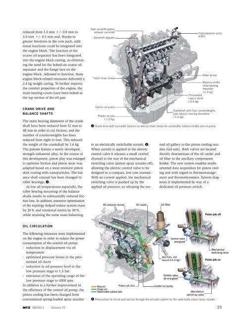
The pistons feature a newly developed,<br />
strength-enhanced alloy. In the course of<br />
this development, piston play was enlarged<br />
to optimise friction and piston wear was<br />
adapted based on a wear-resistant piston<br />
skirt coating with nanoparticles. The balance<br />
shaft concept has been changed to<br />
roller bearings, ❸.<br />
At low oil temperatures especially, the<br />
roller bearing mounting of the balance<br />
shafts results in substantially reduced friction<br />
loss. In addition, intensive optimisation<br />
of the topology helped reduce system mass<br />
by 20 % and rotational inertia by 30 %,<br />
while retaining the same mass balancing.<br />
oIl cIrculatIon<br />
The following measures were implemented<br />
on the engine in order to reduce the power<br />
consumption of the control oil pump:<br />
: reduction in displacement via oil<br />
temperature<br />
: optimised pressure losses in the pressurised<br />
oil ducts<br />
: reduction in oil pressure level in the<br />
low pressure stage to 1.5 bar<br />
: extension of the operating range of the<br />
low pressure stage to 4500 rpm.<br />
In addition to a further improvement in<br />
the efficiency of the control oil pump, the<br />
piston cooling has been changed from<br />
conventional spring-loaded spray nozzles<br />
06I2011 Volume 72<br />
❸ Crank drive with lancaster balance as well as chain drives for camshafts, balance shafts and oil pump<br />
to an electrically switchable system, ❹.<br />
When current is applied to the electric<br />
control valve it releases a small control<br />
channel to the rear of the mechanical<br />
switching valve (piston spray nozzles off),<br />
allowing the electric control valve to be<br />
designed in a compact, low-cost manner.<br />
With no current applied, the mechanical<br />
switching valve is pushed up by the<br />
applied oil pressure, so releasing the sec-<br />
ond oil gallery to the piston cooling nozzles<br />
(fail-safe). Both valves are located<br />
directly downstream of the oil cooler and<br />
oil filter in the ancillary components<br />
holder. The new system enables needsoriented<br />
data acquisition for piston cooling<br />
and with regard to thermomanagement<br />
and thermodynamics. System diagnosis<br />
is implemented by way of a<br />
dedicated oil pressure switch.<br />
❹ Pressurised oil circuit and section through the actuator system for the switchable piston spray nozzles<br />
35