THE NEW 1.8 L TFSl ENGlNE FROM AUDl PART 1: BASE ENGINE ...
THE NEW 1.8 L TFSl ENGlNE FROM AUDl PART 1: BASE ENGINE ...
THE NEW 1.8 L TFSl ENGlNE FROM AUDl PART 1: BASE ENGINE ...

Create successful ePaper yourself
Turn your PDF publications into a flip-book with our unique Google optimized e-Paper software.
Industry GASOlInE EnGInES<br />
The new <strong>1.8</strong> l TFSI engIne From AudI<br />
Part 1: Base engine and<br />
thermomanagement<br />
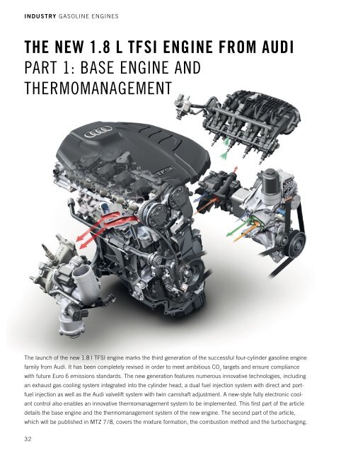
The launch of the new <strong>1.8</strong> l TFSI engine marks the third generation of the successful four-cylinder gasoline engine<br />
family from Audi. It has been completely revised in order to meet ambitious CO 2 targets and ensure compliance<br />
with future Euro 6 emissions standards. The new generation features numerous innovative technologies, including<br />
an exhaust gas cooling system integrated into the cylinder head, a dual fuel injection system with direct and port-<br />
fuel injection as well as the Audi valvelift system with twin camshaft adjustment. A new-style fully electronic cool-<br />
ant control also enables an innovative thermomanagement system to be implemented. This first part of the article<br />
details the base engine and the thermomanagement system of the new engine. The second part of the article,<br />
which will be published in MTZ 7 / 8, covers the mixture formation, the combustion method and the turbocharging.<br />
32
AuTHOrS<br />
dIpl.-Ing. alex eIser<br />
is Head of Engine Development at<br />
Audi AG in Ingolstadt (Germany).<br />
dr.-Ing. JoachIm doerr<br />
is Technical Project Manager for<br />
the EA888 I4 TFSI Engines in the<br />
longitudinally Mounted Engines<br />
Department at Audi AG in Ingolstadt<br />
(Germany).<br />
dIpl.-Ing. mIchael Jung<br />
is Head of Base Engine Mechanics,<br />
Four-Cylinder Inline Petrol Engines<br />
in the Engine Development<br />
Department at Audi AG in Ingolstadt<br />
(Germany).<br />
dr.-Ing. stephan adam<br />
is Head of Flow Calculation in the<br />
Engine Development Department at<br />
Audi AG in Ingolstadt (Germany).<br />
06I2011 Volume 72<br />
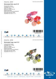
IntroductIon and revIew<br />
The history of Audi inline four-cylinder<br />
TFSI engines extends back to 2004, when<br />
the world’s first direct-injection turbo<br />
engine, based on the tried and proven<br />
EA113 engine series, went into production<br />
as the 2.0 l TFSI [1, 2]. Development of<br />
the concept for the EA888 engine series<br />
with chain drive [3] had actually begun<br />
back in 2003, with the aim of replacing<br />
the successful timing belt driven EA113<br />
series. The EA888 engine was designed<br />
from the very beginning as a “global en -<br />
gine” for the VW Group (across all brands<br />
and platforms) and for worldwide application<br />
(across all markets). Following the<br />
successful launch of this completely new<br />
engine generation in spring 2007 (gen. 1)<br />
[3] and the introduction of the Audi valvelift<br />
system [4] as well as numerous<br />
measures to optimise friction in the 2009<br />
models (gen. 2) [5], a further groundbreaking<br />
optimisation (gen. 3) is about to<br />
be put into production in the Audi A4/A5<br />
family, ❶.<br />
The first and second generation EA888<br />
engines are already more than meeting<br />
their original objective of serving as “global<br />
engines” (i.e. for a wide variety of<br />
vehicle platforms and Group users), having<br />
reached production levels of over one<br />
million units a year.<br />
The inline-four TFSI engine series EA113<br />
and EA888 have achieved an unmatched<br />
record of success since 2005, winning a<br />
total of ten awards in the prestigious “In -<br />
EA113<br />
EA888<br />
Gen.1<br />
EA888<br />
Gen.2<br />
EA888<br />
Gen.3<br />
2.0 l TFSI<br />
S3 / TTS 2.0 l TFSI<br />
<strong>1.8</strong> l TFSI<br />
2.0 l TFSI<br />
Sulev<br />
2004 2005 2006 2007 2008 2009<br />
ternational Engine of the Year” and “10<br />
Best Engines” competitions. The third<br />
generation of the EA888 now marks the<br />
next chapter in the history of inline-four<br />
TFSI engine technology, and is poised to<br />
continue the success story. Other variants<br />
(with varying engine capacity, power output<br />
and torque specifications) are in preparation<br />
alongside the third generation unit<br />
presented here.<br />
engIne features and<br />
technIcal hIghlIghts<br />
The development objectives for the third<br />
generation of the EA888 I4 TFSI engine<br />
series were:<br />
: development of a modular kit for <strong>1.8</strong> l<br />
and 2.0 l variants with a high proportion<br />
of identical components<br />
: installation in all VW Group transverse-mounted<br />
and longitudinalmounted<br />
platforms<br />
: reduction of internal friction in the<br />
engine<br />
: improvement in power, torque and fuel<br />
efficiency<br />
: further improvement in comfort<br />
attributes<br />
: preparation for conformance to all<br />
future emissions standards (e.g. Euro 6)<br />
: preparation for deployment on all<br />
markets<br />
: enhanced robustness for increasing<br />
hybridisation and deployment in<br />
emerging markets<br />
: further weight reduction.<br />
<strong>1.8</strong> l TFSI<br />
2.0 l<br />
TFSI Avs<br />
A4 Q5<br />
Audi valvelift Flexible fuel Hybrid<br />
system<br />
<strong>1.8</strong> l TFSI Avs<br />
Audi valvelift system<br />
❶ roadmap of Audi inline four-cylinder TFSI engine technology [1, 3, 5, 6, 7, 8]<br />
Year<br />
2010 2011 2012 2013 2014<br />
33
Industry GASOlInE EnGInES<br />
For the third generation of the EA888<br />
engine, the tried and proven power train<br />
layout with Lancaster balance was adopted,<br />
also incorporating further improvements<br />
in terms of internal friction. For example,<br />
the main bearing diameter has been further<br />
reduced; the balance shafts are in part<br />
roller bearing mounted; and the pressurised<br />
oil circuit, including the control oil<br />
pump, has been optimised.<br />
To improve the torque characteristic,<br />
the tried and proven Audi valvelift system<br />
has been adopted from the 2.0 l second<br />
generation predecessor engine, and an<br />
additional exhaust camshaft adjuster has<br />
been integrated. The high torque of 320 Nm<br />
at 1500 rpm delivers outstanding performance,<br />
but also in particular low consumption<br />
figures based on modified gearbox<br />
transmission ratios (downspeeding).<br />
An entirely new cylinder head has been<br />
developed for the third generation EA888<br />
and, for the first time in this power and<br />
torque class, the exhaust gas recirculation<br />
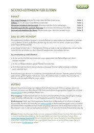
maIn dImensIons unIt value<br />
engIne dImensIons<br />
<strong>1.8</strong> l TFSI Gen.2 <strong>1.8</strong> l TFSI Gen.3<br />
Capacity i 1.798<br />
Stroke mm 84.1<br />
Bore mm 82.5<br />
Stroke/bore (ratio) - 1.02<br />
Distance between cylinders mm 88<br />
Block height mm 220<br />
Con-rod length mm 148<br />
Crankshaft bearing - 5<br />
Main bearing diameter mm 52 48<br />
Con-rod bearing diameter mm 47.8<br />
Piston pin diameter mm 21 23<br />
valve dIameter<br />
: Inlet mm 33.85<br />
: Exhaust mm 28<br />
valve stroke<br />
: Inlet mm 10.7<br />
: Exhaust mm 8 6.35/9<br />
tImIng wIth 1 mm valve stroke<br />
IO retarded °CA after TDC 38 30<br />
IC retarded °CA after BDC 48 40<br />
EO advanced °CA before BDC 28 39/24<br />
EC retarded °CA before TDC 8 -6<br />
camshaft adJustment<br />
Inlet camshaft adjustment range °CA 60<br />
Exhaust camshaft adjustment range °CA - 30<br />
Compression ratio - 9.6<br />
Power output kW at rpm 118 at 4500-6000 125 at 3800-6200<br />
Torque nm at rpm 250 at 1500-4500 320 at 1500-3700<br />
Fuel type rOn 95/91 95<br />
Engine weight to DIn70020 GZ kg 135 131.5<br />
Initial oil charge l 5.4<br />
Emissions standard - Euro 5 Euro 6<br />
❷ Main dimensions of the new <strong>1.8</strong> l EA888 inline four-cylinder TFSI engine compared to its predecessor<br />
34<br />
is fully integrated to the turbocharger.<br />
This water-cooled integrated exhaust gas<br />
cooling system makes it possible to reduce<br />
full-load consumption considerably.<br />
To provide intelligent control of the en -<br />
gine’s heat flows (thermomanagement), a<br />
new-style rotary slide module has been<br />
developed to provide fully electronic coolant<br />
control. In the engine’s warm-up phase<br />
for example, it is able to completely block<br />
the coolant from entering the engine or set<br />
a minimal volumetric flow. When the<br />
engine is warmed up, the coolant temperature<br />
can be quickly and fully variably<br />
adjusted to various temperature levels<br />
according to the load demand and external<br />
conditions.<br />
In order to comply with the future Euro 6<br />
emissions standard, Audi has for the first<br />
time developed a dual fuel injection system<br />
with FSI and MPI injection. The ability<br />
to freely select the injection mode means<br />
that particulate emissions can be reduced<br />
significantly across wide map ranges and<br />
consumption can also be cut.<br />
The weight of the new EA888 series has<br />
been significantly reduced again, despite<br />
numerous additional CO 2 measures. Key<br />
factors in this are the thin-walled engine<br />
block (3 mm thick), a weight-optimised<br />
crankshaft, the integrated exhaust gas<br />
cooling system cylinder head integrated<br />
exhaust manifold, a plastic oil pan, and<br />
the use of aluminium bolts.<br />
❷ sets out the main dimensions and<br />
other characteristic data of the third generation<br />
<strong>1.8</strong> l TFSI engine compared to the<br />
predecessor second generation <strong>1.8</strong> l TFSI.<br />
Base engIne<br />
The focus of the latest development work<br />
on the base engine was on significantly<br />
reducing friction loss while at the same<br />
time cutting engine weight. Moreover, a<br />
maximum identical parts strategy was<br />
implemented in spite of the specified broad<br />
power and torque range (spread from<br />
entry-level to top-of-the-range engine).<br />
engIne Block<br />
Based on the aim of further reducing<br />
the weight and blank tolerances of the<br />
engine block, the casting process was<br />
changed from the conventional flat pouring<br />
to upright pouring. The nominal wall<br />
thickness of the engine block has been
educed from 3.5 mm +/- 0.8 mm to<br />
3.0 mm +/- 0.5 mm and, thanks to<br />
greater freedoms in the core pack, additional<br />
functions could be integrated into<br />
the engine block. The function of the<br />
coarse oil separator has been integrated<br />
into the engine block casting, so eliminating<br />
the need for the bolted-on coarse oil<br />
separator and the flange face on the<br />
engine block. Adjusted to function, these<br />
engine block-related measures delivered a<br />
2.4 kg weight saving. To further improve<br />
the comfort properties of the engine, the<br />
main bearing covers have been bolted to<br />
the top section of the oil pan.<br />
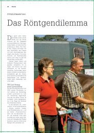
crank drIve and<br />
Balance shafts<br />
The main bearing diameters of the crankshaft<br />
have been reduced from 52 mm to<br />
48 mm in order to cut friction, and the<br />
number of counterweights has been<br />
reduced from eight to four. This reduced<br />
the weight of the crankshaft by 1.6 kg.<br />
The pistons feature a newly developed,<br />
strength-enhanced alloy. In the course of<br />
this development, piston play was enlarged<br />
to optimise friction and piston wear was<br />
adapted based on a wear-resistant piston<br />
skirt coating with nanoparticles. The balance<br />
shaft concept has been changed to<br />
roller bearings, ❸.<br />
At low oil temperatures especially, the<br />
roller bearing mounting of the balance<br />
shafts results in substantially reduced friction<br />
loss. In addition, intensive optimisation<br />
of the topology helped reduce system mass<br />
by 20 % and rotational inertia by 30 %,<br />
while retaining the same mass balancing.<br />
oIl cIrculatIon<br />
The following measures were implemented<br />
on the engine in order to reduce the power<br />
consumption of the control oil pump:<br />
: reduction in displacement via oil<br />
temperature<br />
: optimised pressure losses in the pressurised<br />
oil ducts<br />
: reduction in oil pressure level in the<br />
low pressure stage to 1.5 bar<br />
: extension of the operating range of the<br />
low pressure stage to 4500 rpm.<br />
In addition to a further improvement in<br />
the efficiency of the control oil pump, the<br />
piston cooling has been changed from<br />
conventional spring-loaded spray nozzles<br />
06I2011 Volume 72<br />
❸ Crank drive with lancaster balance as well as chain drives for camshafts, balance shafts and oil pump<br />
to an electrically switchable system, ❹.<br />
When current is applied to the electric<br />
control valve it releases a small control<br />
channel to the rear of the mechanical<br />
switching valve (piston spray nozzles off),<br />
allowing the electric control valve to be<br />
designed in a compact, low-cost manner.<br />
With no current applied, the mechanical<br />
switching valve is pushed up by the<br />
applied oil pressure, so releasing the sec-<br />
ond oil gallery to the piston cooling nozzles<br />
(fail-safe). Both valves are located<br />
directly downstream of the oil cooler and<br />
oil filter in the ancillary components<br />
holder. The new system enables needsoriented<br />
data acquisition for piston cooling<br />
and with regard to thermomanagement<br />
and thermodynamics. System diagnosis<br />
is implemented by way of a<br />
dedicated oil pressure switch.<br />
❹ Pressurised oil circuit and section through the actuator system for the switchable piston spray nozzles<br />
35
Industry GASOlInE EnGInES<br />
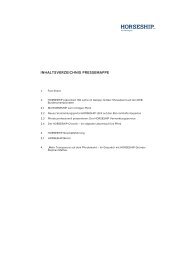
❺ Mean friction pressure characteristic of the new <strong>1.8</strong> l TFSI engine; comparison with FEV spread<br />
36<br />
❻ Cylinder head with<br />
integrated exhaust gas<br />
cooling system, Audi<br />
valvelift system and twin<br />
camshaft adjustment<br />
Thanks to all the friction-reducing<br />
measures on the base engine, the new<br />
EA888 third generation engine series redefines<br />
the friction loss spread for turbocharged<br />
four-cylinder gasoline engines, ❺.<br />
cylInder head<br />
For the new EA888 third generation<br />
engine series, a cylinder head integrated<br />
exhaust gas cooling/routing system with<br />
ignition sequence separation has been<br />
implemented for the first time for turbocharged<br />
direct-injection gasoline engines,<br />
❻. This water-cooled exhaust manifold<br />
means that the need for full load enrichment<br />
is eliminated almost entirely. As<br />
a result, consumption can be greatly<br />
reduced both in normal customer driving<br />
and, especially, when employing a more<br />
sporty driving style. Moreover, the integrated<br />
exhaust manifold aids rapid heatup<br />
of the coolant and so is a key component<br />
of the thermo management system.<br />
Another advantage lies in the convergence<br />
of the gas ducts while still in the<br />
cylinder head, which results in a comparatively<br />
compact and light turbocharger<br />
module. Consequently, the overall cylinder<br />
head/turbocharger balance resulted in<br />
a 1.5 kg weight reduction.<br />
Achieving a thermodynamically and<br />
thermomechanically optimised package of<br />
gas ducts and integrated exhaust manifold<br />
cooling ducts posed a particular challenge<br />
during the development of the cylinder<br />
head, especially with regard to industrialisation<br />
and production castability. The cylinder<br />
head places extremely high demands<br />
on the casting process. A die with twelve<br />
sand cores is produced by the bottom<br />
casting method. To meet the high thermodynamic<br />
demands of the new third generation<br />
<strong>1.8</strong> l engine, the Audi valvelift system<br />
and a second camshaft adjuster have<br />
been integrated on the exhaust side and<br />
the inlet duct has additionally been revised.<br />
To control optimum engine heat-up and to<br />
improve monitoring of the temperatures in<br />
the cylinder head, the coolant temperature<br />
measuring point has been moved from<br />
the engine block into the cylinder head.<br />
cylInder head desIgn<br />
To simulate the integrated exhaust gas<br />
cooling system and its influence on the<br />
thermomechanics of the cylinder head, a
number of new simulation methods were<br />
also developed alongside established CFD<br />
and FEM methods. First, classic CFD simulations<br />
were used to produce the basic<br />
design of the gas and water cores and<br />
combined with FEM methods to thermomechanically<br />
optimise the cylinder head.<br />
As there is intensive coupling between the<br />
exhaust gas and cooling water flows and<br />
heat transport in the aluminium within a<br />
very confined area – that is to say, involving<br />
extreme temperature gradients – in this<br />
project, all three areas (gas, water, aluminium)<br />
were also calculated in a single simulation<br />
model for the first time, ❼ (left). This<br />
methodology enables retroactive effects of<br />
the component temperatures on the fluid<br />
temperatures and the resultant heat flows<br />
to be simulated more accurately.<br />
The development of the integrated<br />
exhaust manifold cylinder head revealed<br />
that, as well as the stationary cooling<br />
design, the load cycles involving negative<br />
load and speed changes are also a key factor.<br />
Immediately after such a change of<br />
operating state, firstly the large amount of<br />
heat stored in the material is discharged<br />
into the cooling water and, secondly, the<br />
cooling water volumetric flow and pressure<br />
decrease dramatically due to the slow<br />
water pump speed caused by the low<br />
engine revs. The hot water jacket areas<br />
are particularly at risk of boiling in this<br />
context, which in the long term may<br />
result in damage to the cooling water.<br />
Extreme cases of such load cycles, as<br />
well as rapid shutdowns, were analysed<br />
both on the test rig and by simulation. In<br />
the final integrated exhaust manifold configuration,<br />
from an integral viewpoint a<br />
comparable level to the predecessor engine<br />
was attained in terms of short-time boiling<br />
intensity, ⑦ (right). This simulation<br />
❽ Engine cooling circuit with interface to passenger compartment heating, gearbox heating and main water<br />
cooler<br />
06I2011 Volume 72<br />
❼ Simulation of the thermomechanics of the integrated exhaust gas cooling system: integrated CAE model<br />
with temperature distribution (left), boiling response in the cylinder head at full load with negative engine<br />
speed jump (right)<br />
methodology, too, was deployed for the<br />
first time in the course of the integrated<br />
exhaust manifold development.<br />
thermomanagement/coolIng<br />
The complete cooling water circuit – both<br />
internally inside the engine and on the<br />
vehicle side – was designed throughout to<br />
provide innovative thermomanagement<br />
(ITM), resulting in rapid heat-up of the<br />
en gine and, as required, of the vehicle<br />
interior. The two main components of the<br />
thermomanagement system are the integrated<br />
exhaust gas cooling system as already<br />
described and the rotary slide module for<br />
implementing fully electronic coolant control.<br />
The complete cooling circuit additionally<br />
features switching valves to activate<br />
or block the flow through the heater<br />
and the gear oil heat exchanger, ❽.<br />
fully electronIc<br />
coolant control<br />
The central actuating element for the fully<br />
electronic coolant control and thermomanagement<br />
system is the plastic rotary<br />
slide module, housing two mechanically<br />
coupled rotary slides which regulate the<br />
cooling water flow, ❾. An electric motor<br />
drives rotary slide 1 by way of a heavily<br />
downspeeded worm gear. This is in turn<br />
connected via lantern gear toothing to<br />
rotary slide 2. Rotary slide 1 replaces the<br />
conventional wax thermostat, and is able<br />
to vary the cooling water temperature<br />
37
Industry GASOlInE EnGInES<br />
❾ rotary slide module for fully electronic control<br />
of the heat flows in the engine and the vehicle<br />
infinitely as required between 85 °C and<br />
107 °C. Rotary slide 1 additionally regulates<br />
the cooling water return from the<br />
engine oil cooler.<br />
heat-up strategy<br />
During the warm-up phase, the cooling<br />
water flow into the engine is initially completely<br />
blocked by rotary slide 2. All external<br />
valves are closed, the water is standing<br />
throughout the engine. When heating<br />
is requested (in real-life customer operation),<br />
the standing water does not have to<br />
be completely used up. In this case there<br />
is an autonomous heating circuit with a<br />
dedicated auxiliary water pump via<br />
which the waste heat from the integrated<br />
exhaust manifold cylinder head is fed to<br />
the passenger compartment heater. The<br />
cooling water inlet into the engine block<br />
(rotary slide 2) remains closed, so maintaining<br />
the rapid heat-up function of the<br />
cylinder liners and reducing friction. The<br />
autonomous heating system means the<br />
customer’s comfort demands can be met<br />
and at the same time the optimum heatup<br />
strategy is implemented to minimise<br />
friction.<br />
Finally, as the engine temperature rises<br />
further, rotary slide 2 is slowly opened.<br />
This generates the minimum necessary<br />
cooling water volumetric flow to ensure<br />
adequate cooling of the components. The<br />
38<br />
very rapid heat-up of the water further<br />
minimises friction in the warm-up phase.<br />
Ultimately, as from a specified water temperature,<br />
the engine oil is additionally<br />
heated by targeted activation of the<br />
engine oil cooler by way of rotary slide 1.<br />
Once the engine has been sufficiently<br />
warmed through, the switching valve to<br />
the gear oil cooler is finally opened so as<br />
also to warm up the gear oil with the surplus<br />
heat. The flow through the main<br />
water cooler entails heat loss to the surrounding<br />
environment and so, to deliver<br />
maximum fuel efficiency, occurs at the<br />
latest possible time. The integrated<br />
exhaust gas cooling system and the fully<br />
electronic coolant control thus provide the<br />
engine with a much shorter warm-up<br />
phase than its predecessor, and additionally<br />
speed up passenger compartment<br />
heating, ❿ (top).<br />
❿ Thermomanagement properties: engine heat-up curve in the nEDC (top), cooling water temperature control<br />
across the map (bottom)
temperature control<br />
The innovative thermomanagement system<br />
permits optimum setting of the cooling<br />
water temperatures across the entire map<br />
so as to minimise friction and maximise<br />
thermodynamic efficiency. At low engine<br />
speeds and loads, the cooling water is<br />
adjusted to 107 °C in order to minimise<br />
engine friction. As the load and engine<br />
speed rise, the cooling water temperature<br />
is then lowered down to 85 °C, ⑩ (bottom).<br />
This provides the best possible compromise<br />
between reduced friction and optimum<br />
ignition efficiency (and minimum<br />
knocking), so ensuring optimum overall<br />
engine efficiency. The high adjustment<br />
speed of the rotary slide module and the<br />
high dynamism of coolant control achieved<br />
as a result enable the coolant temperature<br />
to be lowered very rapidly for the jump to<br />
high loads. As a result, temperature overshoots<br />
in the components can be avoided.<br />
The innovative thermomanagement<br />
system is rounded off by a special run-on<br />
function which is activated when the<br />
engine is switched off. The electric heating<br />
pump and a run-on setting of the<br />
rotary slide module then allow a targeted<br />
flow through the boil-sensitive cylinder<br />
head and turbocharger via the main water<br />
cooler, so enabling rapid discharge of the<br />
heat stored in those components.<br />
06I2011 Volume 72<br />
There is no flow through the engine<br />
block in the run-on position, so as not to<br />
cool the cylinder liners unnecessarily.<br />
This function significantly reduced the<br />
run-on time, without generating excessive<br />
heat loss. Overall, the ITM delivers a consumption<br />
advantage of 2.5 g CO 2 /km in<br />
the NEDC, with significant savings also in<br />
customer driving modes. It also provides<br />
high levels of comfort thanks to rapid<br />
heat-up of the passenger compartment.<br />
references<br />
[1] Krebs, r.; Böhme, J.; Dornhöfer, r.; Wurms,<br />
r.; Friedmann, K.; Helbig, J.; Hatz, W.: Der neue<br />
Audi 2,0T FSI Motor – Der erste direkteinspritzende<br />
Turbo-Ottomotor bei Audi. 25. Wiener<br />
Motoren Symposium, Wien 2004<br />
[2] Wurms, r.; Kuhn, M.; Zeilbeck, A.; Adam, S.;<br />
Krebs, r.; Hatz, W.: Die Audi Turbo FSI Technologie.<br />
13. Aachener Kolloquium – Fahrzeug- und<br />
Motorentechnik, Aachen 2004<br />
[3] Böhme, J.; Hatz, W.; Eiser, A.; Dornhöfer, r.;<br />
Ehret, W.; Wurms, r.: Der neue r4-1,8 l T-FSI-<br />
Motor von Audi. 15. Aachener Kolloquium –<br />
Fahrzeug- und Motorentechnik, Aachen 2006<br />
[4] Wurms, r.; Dengler, S.; Budack, r.; Mendl, G.;<br />
Dicke, T.; Eiser, A.: Audi valvelift system – ein<br />
neues innovatives Ventiltriebssystem von Audi.<br />
15. Aachener Kolloquium – Fahrzeug- und<br />
Motorentechnik, Aachen 2006<br />
[5] Wurms, r.; Budack, r.; Böhme, J.; Dornhöfer,<br />
r.; Eiser, A.; Hatz, W.: Der neue 2.0l-TFSI mit<br />
Audi valvelift system für den Audi A4 – die<br />
nächste Generation der Audi Turbo-FSI-Technologie.<br />
17. Aachener Kolloquium – Fahrzeug- und<br />
Motorentechnik, Aachen 2008<br />
[6] Dornhöfer, r.; Hatz, W.; Eiser, A.; Böhme, J.;<br />
Adam, S.; unselt, F.; Cerulla, S.; Zimmer, M.;<br />
Friedmann, K.; uhl, W.: Der neue r4 2,0l 4V<br />
TFSI-Motor im Audi S3. 11. Aufladetechnische<br />
Konferenz, Dresden 2006<br />
[7] Eiglmeier, C.; Pfalzgraf, B.; Helbig, J.; Adam,<br />
S.; Grigo, M.; Dornhöfer, r.; Eiser, A.: Der neue<br />
r4 – 2,0l TFSI SulEV/PZEV-Motor von AuDI.<br />
16. Aachener Kolloquium – Fahrzeug- und<br />
Motorentechnik, Aachen 2007<br />
[8] Ballauf, J.; Hatz, W.; Eiser, A.; Dornhöfer, r.;<br />
Grigo, M.; Ewald, A.; Stichlmeir, M.: AuDI 2.0l<br />
TFSI flexible fuel. 12. Tagung “Der Arbeitsprozess<br />
des Verbrennungsmotors”, Technische universität<br />
Graz, 24./25. September 2009<br />
ThAnKS<br />
The following people also assisted in producing<br />
this article:<br />
: Dipl.-Ing. Dirk Schöneberg, Team leader<br />
Vehicle Integration and Thermomanage-<br />
ment, four- and six-cylinder petrol engines,<br />
at Audi AG in Ingolstadt (Germany).<br />
: Dipl.-Ing. Stefan rank, Specialist in thermo-<br />
management, four-cylinder petrol engines,<br />
at Audi AG in Ingolstadt (Germany).<br />
: Dipl.-Ing Steffen Triebe, Component Man-<br />
ager, Designer of the rotary slide module for<br />
the fully electronic coolant control system,<br />
at Audi AG in Ingolstadt (Germany).<br />
39