THE NEW 1.8 L TFSl ENGlNE FROM AUDl PART 1: BASE ENGINE ...
THE NEW 1.8 L TFSl ENGlNE FROM AUDl PART 1: BASE ENGINE ...
THE NEW 1.8 L TFSl ENGlNE FROM AUDl PART 1: BASE ENGINE ...

You also want an ePaper? Increase the reach of your titles
YUMPU automatically turns print PDFs into web optimized ePapers that Google loves.
number of new simulation methods were<br />
also developed alongside established CFD<br />
and FEM methods. First, classic CFD simulations<br />
were used to produce the basic<br />
design of the gas and water cores and<br />
combined with FEM methods to thermomechanically<br />
optimise the cylinder head.<br />
As there is intensive coupling between the<br />
exhaust gas and cooling water flows and<br />
heat transport in the aluminium within a<br />
very confined area – that is to say, involving<br />
extreme temperature gradients – in this<br />
project, all three areas (gas, water, aluminium)<br />
were also calculated in a single simulation<br />
model for the first time, ❼ (left). This<br />
methodology enables retroactive effects of<br />
the component temperatures on the fluid<br />
temperatures and the resultant heat flows<br />
to be simulated more accurately.<br />
The development of the integrated<br />
exhaust manifold cylinder head revealed<br />
that, as well as the stationary cooling<br />
design, the load cycles involving negative<br />
load and speed changes are also a key factor.<br />
Immediately after such a change of<br />
operating state, firstly the large amount of<br />
heat stored in the material is discharged<br />
into the cooling water and, secondly, the<br />
cooling water volumetric flow and pressure<br />
decrease dramatically due to the slow<br />
water pump speed caused by the low<br />
engine revs. The hot water jacket areas<br />
are particularly at risk of boiling in this<br />
context, which in the long term may<br />
result in damage to the cooling water.<br />
Extreme cases of such load cycles, as<br />
well as rapid shutdowns, were analysed<br />
both on the test rig and by simulation. In<br />
the final integrated exhaust manifold configuration,<br />
from an integral viewpoint a<br />
comparable level to the predecessor engine<br />
was attained in terms of short-time boiling<br />
intensity, ⑦ (right). This simulation<br />
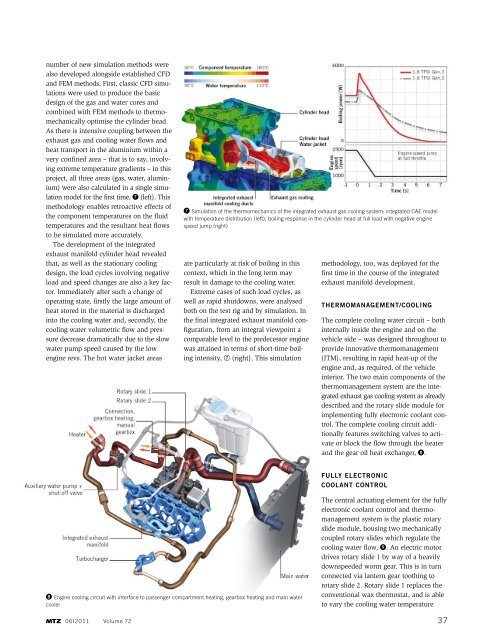
❽ Engine cooling circuit with interface to passenger compartment heating, gearbox heating and main water<br />
cooler<br />
06I2011 Volume 72<br />
❼ Simulation of the thermomechanics of the integrated exhaust gas cooling system: integrated CAE model<br />
with temperature distribution (left), boiling response in the cylinder head at full load with negative engine<br />
speed jump (right)<br />
methodology, too, was deployed for the<br />
first time in the course of the integrated<br />
exhaust manifold development.<br />
thermomanagement/coolIng<br />
The complete cooling water circuit – both<br />
internally inside the engine and on the<br />
vehicle side – was designed throughout to<br />
provide innovative thermomanagement<br />
(ITM), resulting in rapid heat-up of the<br />
en gine and, as required, of the vehicle<br />
interior. The two main components of the<br />
thermomanagement system are the integrated<br />
exhaust gas cooling system as already<br />
described and the rotary slide module for<br />
implementing fully electronic coolant control.<br />
The complete cooling circuit additionally<br />
features switching valves to activate<br />
or block the flow through the heater<br />
and the gear oil heat exchanger, ❽.<br />
fully electronIc<br />
coolant control<br />
The central actuating element for the fully<br />
electronic coolant control and thermomanagement<br />
system is the plastic rotary<br />
slide module, housing two mechanically<br />
coupled rotary slides which regulate the<br />
cooling water flow, ❾. An electric motor<br />
drives rotary slide 1 by way of a heavily<br />
downspeeded worm gear. This is in turn<br />
connected via lantern gear toothing to<br />
rotary slide 2. Rotary slide 1 replaces the<br />
conventional wax thermostat, and is able<br />
to vary the cooling water temperature<br />
37