

Eaton 9395 Field Installed UPM Mechanical ... - Jonweb.net
Eaton 9395 Field Installed UPM Mechanical ... - Jonweb.net
Eaton 9395 Field Installed UPM Mechanical ... - Jonweb.net

You also want an ePaper? Increase the reach of your titles
YUMPU automatically turns print PDFs into web optimized ePapers that Google loves.
FIELD INSTALLED <strong>UPM</strong> INSTALLATION<br />
7. Locate the small flat bracket and screws from the hardware kit. Align the holes in<br />
the small flat bracket over holes in the top of the FI−<strong>UPM</strong> and UPS cabi<strong>net</strong>s.<br />
Secure the bracket with the screws from the hardware kit.<br />
8. Reinstall the FI−<strong>UPM</strong> front panel removed in Step 6, and secure with the retained<br />
hardware.<br />
9. If permanently mounting the system, proceed to Step 10; otherwise, continue to<br />
Step 12.<br />
10. Using the retained hardware, reinstall the left shipping bracket removed in<br />
paragraph 4.2, Step 2 on page 4−1 to the left side of the FI−<strong>UPM</strong> cabi<strong>net</strong> with<br />
the angle facing outward (see Figure 4-1 on page 4−2).<br />
11. Secure the cabi<strong>net</strong> to the floor with customer−supplied hardware.<br />
12. Proceed to paragraph 4.4.<br />
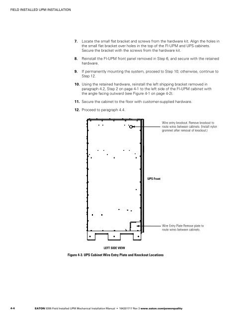
Wire entry knockout. Remove knockout to<br />
route wires between cabi<strong>net</strong>s. (Install nylon<br />
grommet after removal of knockout.)<br />
UPS Front<br />
Wire Entry Plate Remove plate to<br />
route wires between cabi<strong>net</strong>s.<br />
LEFT SIDE VIEW<br />
Figure 4-3. UPS Cabi<strong>net</strong> Wire Entry Plate and Knockout Locations<br />
4−4<br />
EATON <strong>9395</strong> <strong>Field</strong> <strong>Installed</strong> <strong>UPM</strong> <strong>Mechanical</strong> Installation Manual 164201717 Rev 3 www.eaton.com/powerquality


