

Liebert SmartSwitch - Emerson Network Power
Liebert SmartSwitch - Emerson Network Power
Liebert SmartSwitch - Emerson Network Power

You also want an ePaper? Increase the reach of your titles
YUMPU automatically turns print PDFs into web optimized ePapers that Google loves.
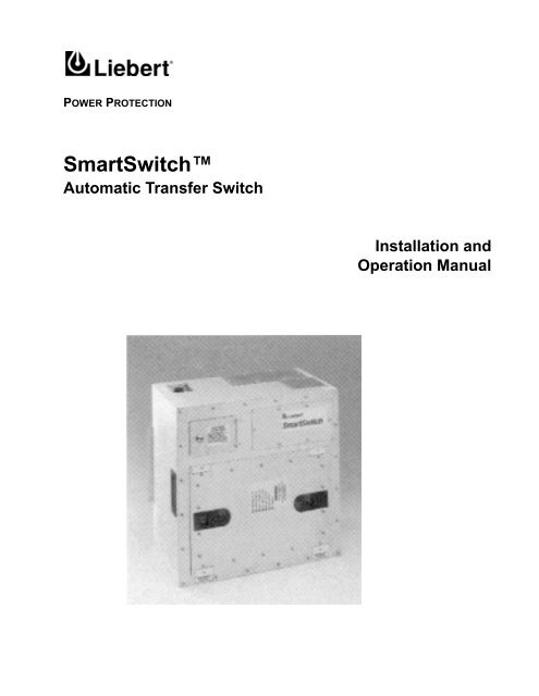
POWER PROTECTION<br />
<strong>SmartSwitch</strong><br />
Automatic Transfer Switch<br />
Installation and<br />
Operation Manual
TABLE OF CONTENTS<br />
IMPORTANT SAFETY INSTRUCTIONS . . . . . . . . . . . . . . . . . . . . . . . . . . . . . . . . . . . . . . . . . . . . .1<br />
1.0 INTRODUCTION . . . . . . . . . . . . . . . . . . . . . . . . . . . . . . . . . . . . . . . . . . . . . . . . . . . . . . .2<br />
1.1 Specifications . . . . . . . . . . . . . . . . . . . . . . . . . . . . . . . . . . . . . . . . . . . . . . . . . . . . . . . . . . . . 2<br />
1.1.1 General Specifications . . . . . . . . . . . . . . . . . . . . . . . . . . . . . . . . . . . . . . . . . . . . . . . . . . . . . . 2<br />
1.1.2 Electrical Specifications. . . . . . . . . . . . . . . . . . . . . . . . . . . . . . . . . . . . . . . . . . . . . . . . . . . . . 3<br />
1.1.3 Environmental Specifications . . . . . . . . . . . . . . . . . . . . . . . . . . . . . . . . . . . . . . . . . . . . . . . . 3<br />
2.0 UNPACKING AND INSTALLATION. . . . . . . . . . . . . . . . . . . . . . . . . . . . . . . . . . . . . . . . . . .5<br />
2.1 Location Considerations. . . . . . . . . . . . . . . . . . . . . . . . . . . . . . . . . . . . . . . . . . . . . . . . . . . . 5<br />
2.2 Input and Output <strong>Power</strong> Connections. . . . . . . . . . . . . . . . . . . . . . . . . . . . . . . . . . . . . . . . . 6<br />
2.3 Grounding . . . . . . . . . . . . . . . . . . . . . . . . . . . . . . . . . . . . . . . . . . . . . . . . . . . . . . . . . . . . . . 10<br />
2.4 Control Wiring Connections. . . . . . . . . . . . . . . . . . . . . . . . . . . . . . . . . . . . . . . . . . . . . . . . 10<br />
3.0 OPERATING INSTRUCTIONS . . . . . . . . . . . . . . . . . . . . . . . . . . . . . . . . . . . . . . . . . . . . . 11<br />
3.1 Description of <strong>SmartSwitch</strong> Operation . . . . . . . . . . . . . . . . . . . . . . . . . . . . . . . . . . . . . . . 11<br />
3.2 Status Indicators . . . . . . . . . . . . . . . . . . . . . . . . . . . . . . . . . . . . . . . . . . . . . . . . . . . . . . . . 11<br />
3.3 RS-232 Communications Port . . . . . . . . . . . . . . . . . . . . . . . . . . . . . . . . . . . . . . . . . . . . . . 12<br />
4.0 OPERATOR CONTROLS . . . . . . . . . . . . . . . . . . . . . . . . . . . . . . . . . . . . . . . . . . . . . . . .14<br />
4.1 Bypass/Transfer Control Switch . . . . . . . . . . . . . . . . . . . . . . . . . . . . . . . . . . . . . . . . . . . . 14<br />
5.0 OPERATING GUIDELINES . . . . . . . . . . . . . . . . . . . . . . . . . . . . . . . . . . . . . . . . . . . . . . .15<br />
6.0 MAINTENANCE . . . . . . . . . . . . . . . . . . . . . . . . . . . . . . . . . . . . . . . . . . . . . . . . . . . . . .17<br />
i
FIGURES<br />
Figure 1 Typical <strong>SmartSwitch</strong> One-Line Diagram . . . . . . . . . . . . . . . . . . . . . . . . . . . . . . . . . . . . . . . . . . 2<br />
Figure 2 Typical 15 to 20 Amp <strong>SmartSwitch</strong> Rackmount Unit . . . . . . . . . . . . . . . . . . . . . . . . . . . . . . . . 7<br />
Figure 3 Typical 25 to 60 Amp <strong>SmartSwitch</strong> Underfloor / Wallmount Unit . . . . . . . . . . . . . . . . . . . . . . 8<br />
Figure 4 Typical Input and Output <strong>Power</strong> Connections . . . . . . . . . . . . . . . . . . . . . . . . . . . . . . . . . . . . . . 9<br />
Figure 5 Control Wiring Connections . . . . . . . . . . . . . . . . . . . . . . . . . . . . . . . . . . . . . . . . . . . . . . . . . . . 10<br />
Figure 6 Bypass / Transfer Control Switch . . . . . . . . . . . . . . . . . . . . . . . . . . . . . . . . . . . . . . . . . . . . . . . 14<br />
TABLES<br />
Table 1 <strong>SmartSwitch</strong> Ratings . . . . . . . . . . . . . . . . . . . . . . . . . . . . . . . . . . . . . . . . . . . . . . . . . . . . . . . . 4<br />
Table 2 <strong>SmartSwitch</strong> Status Indicators . . . . . . . . . . . . . . . . . . . . . . . . . . . . . . . . . . . . . . . . . . . . . . . . . 11<br />
Table 3 RS-232 ASCII Communication Port Customer Commands . . . . . . . . . . . . . . . . . . . . . . . . . . . 12<br />
Table 4 Example View Status Response . . . . . . . . . . . . . . . . . . . . . . . . . . . . . . . . . . . . . . . . . . . . . . . . . 12<br />
Table 5 Example View Event Log Response . . . . . . . . . . . . . . . . . . . . . . . . . . . . . . . . . . . . . . . . . . . . . . 13<br />
Table 6 Example View Settings Response . . . . . . . . . . . . . . . . . . . . . . . . . . . . . . . . . . . . . . . . . . . . . . . 13<br />
Table 7<br />
ii
IMPORTANT SAFETY INSTRUCTIONS<br />
!<br />
WARNING<br />
THERE ARE NO USER-SERVICEABLE PARTS INSIDE THE<br />
REMOVABLE ELECTRONICS MODULE. OPENING OR<br />
REMOVING THE COVER OF THE REMOVABLE ELECTRONICS<br />
MODULE MAY EXPOSE HAZARDOUS VOLTAGES, EVEN WHEN<br />
THE SMARTSWITCH IS IN BYPASS. DO NOT ATTEMPT TO<br />
SERVICE THIS PRODUCT YOURSELF. REFER ALL SERVICING<br />
TO QUALIFIED SERVICE PERSONNEL.<br />
NOTE<br />
Read the entire User’s Manual before installing and operating the<br />
<strong>SmartSwitch</strong>. Adhere to all operating instructions and warnings on the<br />
unit and in this manual.<br />
<strong>Liebert</strong> Corporation neither recommends nor knowingly sells this product<br />
for use with life support or other FDA-designated “critical” devices.<br />
The <strong>SmartSwitch</strong> is suitable for indoor use only. Protect unit from<br />
excessive moisture and install in an area free from flammable liquids,<br />
gases, or corrosive substances.<br />
The unit is designed to operate from solidly grounded AC power sources<br />
only. Provide input overcurrent protection in accordance with the unit<br />
ratings. Wire and ground the unit according to national and local<br />
electrical safety codes.<br />
!<br />
!<br />
!<br />
CAUTION<br />
The unit is supplied by two power sources. Unit may be<br />
electrically live if either of the two input sources is ON, even<br />
when the electronics module is removed. To isolate the unit, turn<br />
OFF and lock out BOTH input power sources.<br />
CAUTION<br />
If unit is furnished with input power plugs, the ground (earth)<br />
leakage current must not exceed 2.75 milliamperes. Most<br />
information technology equipment meets this requirement if no<br />
more than 4 pieces of equipment are powered from this unit. Note:<br />
These instructions may be modified by local wiring regulations.<br />
CAUTION<br />
This unit complies with the limits for a Class A digital device,<br />
pursuant to Part 15 Subpart J of the FCC rules. These limits<br />
provide reasonable protection against harmful interference in a<br />
commercial environment. This unit generates, uses and radiates<br />
radio frequency energy and, if not installed and used in<br />
accordance with this instruction manual, may cause harmful<br />
interference to radio communications. Operation of this unit in a<br />
residential area may cause harmful interference which the user<br />
must correct at his own expense.<br />
1
1.0 INTRODUCTION<br />
The <strong>SmartSwitch</strong> is an automatic transfer switch designed to provide fast automatic transfers<br />
between two independent, synchronous AC power sources to provide continuity of AC power to<br />
critical equipment, such as information technology equipment, despite irregularities in either of<br />
the two AC input power sources. The transfer is accomplished with sense and transfer times of<br />
less than 6 milliseconds. The <strong>SmartSwitch</strong> is available in a 2, 3, or 4 pole configurations, with<br />
ampacities of 13, 15, 20, 25, 30, 50, or 60 amps, in a floor, wall, or rack mount packages. Inputs<br />
may be hardwired or plug connected to the two input branch circuits. Outputs may be receptacles<br />
or hardwired connected to the load equipment.<br />
The <strong>SmartSwitch</strong> consists of two modules, a fixed module containing the input and output connections<br />
and bypass switch with a compartment that holds the plug-in and removable electronics/<br />
switching module. Figure 1 shows a typical one-line schematic diagram of the <strong>SmartSwitch</strong>.<br />
Figure 1<br />
Typical <strong>SmartSwitch</strong> One-Line Diagram<br />
1.1 Specifications<br />
1.1.1 General Specifications<br />
• Manual and Automatic Transfers.<br />
• Sense and Transfer Time: Less than 6 milliseconds.<br />
• Break-Before-Make Switching.<br />
• Selectable Preferred Source.<br />
• Selectable Auto/Manual Retransfer.<br />
• Retransfer Time Delay: 1 to 60 seconds adjustable.<br />
• In-Phase Transfer Window: 1 to 20 degrees adjustable.<br />
• Output Overload Transfer Inhibit: 1 to 10 times full load current adjustable.<br />
• Programmable Switch Self Test.<br />
• Convection Cooling.<br />
2 Introduction
1.1.2 Electrical Specifications<br />
• Nominal input voltage<br />
120 or 208 volts single phase 2W+G, 60 Hz<br />
220, 230, or 240 volts single phase 2W+G, 50 Hz<br />
208/120 volts single phase 3W+G, 60 Hz<br />
208 volts three phase, 3W+G, 60 Hz<br />
208/120 volts three phase, 4W+G, 60 Hz<br />
380, 400, or 415 volts three-phase 3W+G, 50 Hz<br />
380/220, 400/230, or 415/240 volts three phase 4W+G, 50 Hz<br />
Solidly grounded power sources<br />
• Branch circuit breaker rating<br />
15, 20, 30, or 60 amps, 60 Hz<br />
13, 25, or 50 amps, 50 Hz<br />
• Maximum continuous current<br />
12, 16, 24, or 48 amps, 60 Hz<br />
13, 25, or 50 amps, 50 Hz<br />
• Load power factor range: 0.5 to 1.0, leading or lagging.<br />
• Load crest factor: up to 3.5.<br />
• Source voltage distortion: up to 10% THD.<br />
• Overload capability: 125% of continuous current for 2 hours, 1000% for 2 cycles minimum.<br />
• Overcurrent Protection: External overcurrent protection provided by the supply branch circuit<br />
breakers.<br />
• Short circuit withstand capability: up to 20,000 symmetrical amps, protected by internal fusing.<br />
• Withstands Transient Voltage Surges up to 6 kV as defined by IEEE C62.41 for Category A3.<br />
• Meets FCC Part 15 Class A Emission Limits.<br />
• ETL Listed under UL Standard 1008.<br />
• 50 Hz units are CE marked for compliance with the EMC and Low Voltage Directives.<br />
• Redundant Control <strong>Power</strong> Supplies.<br />
• Integral Maintenance Bypass.<br />
• Eight Isolated Normally Open, Form A Switch Status Contacts.<br />
• RS-232 Communications Port<br />
• Hot-Swap, Plug-In Electronics Module.<br />
1.1.3 Environmental Specifications<br />
• Storage temperature range: -40° to +60°C<br />
• Operating temperature range: 0° to 40°C.<br />
• Relative Humidity: 0 to 95% without condensation<br />
• Operating Altitude: up to 5000 feet (1500 meters) above sea level without derating.<br />
• Storage/Transport Altitude: up to 40,000 feet (12,000 meters) above sea level.<br />
• Audible Noise: less than 45 dBA at 5 feet (1.5 meters).<br />
Introduction 3
Table 1<br />
<strong>SmartSwitch</strong> Ratings<br />
Connector<br />
No. of Conductors OPD* Enclosure<br />
Designation Receptacle Voltage Phase Neutral Gnd Poles Amps Type Refer to<br />
IBMA 3743 208 2 — 1 2 20 R Figure 2<br />
IBMB 3744 208 3 — 1 3 15 U Figure 3<br />
IBMC 3753 208 2 — 1 2 30 U Figure 3<br />
IBMD 3754 208 3 — 1 3 30 U Figure 3<br />
IBME 7324 208 3 — 1 3 60 U Figure 3<br />
420R9V 420R9V 208 3 — 1 3 20 U Figure 3<br />
460R9V 460R9V 208 3 — 1 3 60 U Figure 3<br />
515R2 5262 120 1 1 1 1 15 U Figure 3<br />
515R4 (2) 5262 120 1 1 1 1 15 R Figure 2<br />
520R2 5362 120 1 1 1 1 20 R Figure 2<br />
520R4 (2) 5362 120 1 1 1 1 20 R Figure 2<br />
530R1 9308 120 1 1 1 1 30 U Figure 3<br />
615R2 5662 208 2 — 1 2 15 R Figure 2<br />
620R2 5462 208 2 — 1 2 20 R Figure 2<br />
630R1 9330 208 2 — 1 2 30 U Figure 3<br />
1420R1 8410 120/208 2 1 1 2 20 U Figure 3<br />
1430R1 9430 120/208 2 1 1 2 30 U Figure 3<br />
1520R1 8420 208 3 — 1 3 20 U Figure 3<br />
L515R1 4710 120 1 1 1 1 15 R Figure 2<br />
L520R1 2310 120 1 1 1 1 20 R Figure 2<br />
L530R1 2610 120 1 1 1 1 30 U Figure 3<br />
L615R1 4560 208 2 — 1 2 15 R Figure 2<br />
L620R1 2320 208 2 — 1 2 20 R Figure 2<br />
L630R1 2620 208 2 — 1 2 30 U Figure 3<br />
L1420R1 2410 120/208 2 1 1 2 20 U Figure 3<br />
L1430R1 2710 120/208 2 1 1 2 30 U Figure 3<br />
L1520R1 2420 208 3 — 1 3 20 U Figure 3<br />
L1530R1 2720 208 3 — 1 3 30 U Figure 3<br />
L2120R1 2510 120/208 3 1 1 3 20 U Figure 3<br />
L2130R1 2810 120/208 3 1 1 3 30 U Figure 3<br />
FW120 None 120 1 1 1 1 20 R Figure 2<br />
FW130 None 120 1 1 1 1 30 U Figure 3<br />
FW220 None 208 2 — 1 2 20 R Figure 2<br />
FW230 None 208 2 — 1 2 30 U Figure 3<br />
FW230N None 208/120 2 1 1 2 30 U Figure 3<br />
FW330 None 208 3 — 1 3 30 U Figure 3<br />
FW330N None 208/120 3 1 1 3 30 U Figure 3<br />
FW360 None 208 3 — 1 3 60 U Figure 3<br />
FW113 None 230 1 1 1 1 13 R Figure 2<br />
FW325N None 400/230 3 1 1 3 25 U Figure 3<br />
FW350 None 400 3 — 1 3 50 U Figure 3<br />
Consult Factory for other available connectors not shown.<br />
* OPD - Maximum size of Overcurrent Protection Device (fuse or circuit breaker) supplying <strong>SmartSwitch</strong>.<br />
4 Introduction
2.0 UNPACKING AND INSTALLATION<br />
A quality installation begins on the receiving dock.<br />
Upon receipt and before unpacking, inspect the shipping container for damage or mishandling. If<br />
carton is damaged, note on shipper’s receipt and check for concealed damage. If any damage as a<br />
result of shipping is observed, file a damage claim with the shipper within 24 hours and contact<br />
your local <strong>Liebert</strong> representative or <strong>Liebert</strong> Customer Service and Support at 1-800-543-2378 to<br />
inform them of the damage claim and the condition of the equipment.<br />
If unit is to be stored before installation, it is recommended to store the unit in a dry environment<br />
with temperatures in the range of 0°C to 40°C. Use original packing materials or other suitable<br />
means to keep the unit clean. When opening the shipping carton, use care not to puncture the carton<br />
with sharp objects.<br />
The unit is of a size and weight that it can be easily moved to its intended location. Refer to the<br />
unit dimensions shown in Figure 2 and Figure 3. Typical unit weights are less than 70 pounds<br />
(32 kg) for the wall or underfloor enclosure and less than 40 pounds (18 kg) for the rackmount<br />
enclosure.<br />
2.1 Location Considerations<br />
The unit is designed to be installed indoors where the ambient air temperature is in the range of<br />
0°C and 40°C with a relative humidity of 0% to 95% non-condensing.<br />
The underfloor and wall mount enclosures are designed to withstand moderate amounts of moisture<br />
such as is normally available under a computer room raised floor. Do not operate the units in<br />
standing water.<br />
!<br />
CAUTION:<br />
Do not locate or operate the unit in hazardous areas where there<br />
is conductive or explosive dust, flammable liquids or gases, or<br />
corrosive substances.<br />
Altitude - The standard units are designed for full load operation up to 5000 feet (1500 meters)<br />
above sea level. For higher altitude applications, contact your local <strong>Liebert</strong> Representative or<br />
applications engineering.<br />
Heat Output - The units produce minimal heat output during normal operation. The typical heat<br />
output, which should be included in any calculations for room heat load, is less than 260 BTU/<br />
Hour (80 W/Hour).<br />
Rackmount Installation - The rackmount enclosure is designed to fit into an EIA Standard 19<br />
inch rack. For rackmount installation, support the unit on a shelf, bracket, or slide. Do not secure<br />
only by the front mounting plate. Secure the unit into the rack using four screws through the<br />
front plate. See Figure 2.<br />
Unpacking and Installation 5
2.2 Input and Output <strong>Power</strong> Connections<br />
All wiring should be installed by a qualified electrician. All wiring must comply with NEC and<br />
applicable local codes.<br />
!<br />
!<br />
WARNING<br />
RISK OF ELECTRICAL SHOCK. HAZARDOUS VOLTAGES ARE<br />
PRESENT INSIDE THE SMARTSWITCH. VERIFY THAT THE ALL<br />
INPUT POWER SOURCES ARE DE-ENERGIZED AND LOCKED<br />
OUT BEFORE MAKING CONNECTIONS INSIDE THE UNIT. THE<br />
SMARTSWITCH IS INTENDED TO BE FED FROM TWO<br />
SOURCES. BE SURE ALL SOURCES OF POWER ARE DE-<br />
ENERGIZED AND LOCKED OUT BEFORE MAKING<br />
CONNECTIONS INSIDE THE UNIT.<br />
WARNING<br />
RISK OF UNIT DAMAGE. THE SMARTSWITCH IS INTENDED TO<br />
BE OPERATED FROM SOLIDLY GROUNDED POWER SOURCES.<br />
OPERATION FROM OTHER THAN SOLIDLY GROUNDED<br />
POWER SOURCES MAY CAUSE MISOPERATION OR DAMAGE<br />
TO THE UNIT.<br />
If the unit is not furnished with input power cables, then input power connections are made to<br />
terminal blocks located inside the unit. Refer to the unit outline drawings furnished with the unit<br />
or Figure 2 and Figure 3 for the location of the input power connections. Terminal blocks for<br />
switches rated 13 to 20 amps accept wires sizes of #14 to #10 AWG. Terminal blocks for switches<br />
rated 25 to 60 amps accept wire sizes of #12 to #6 AWG.<br />
Wire Size<br />
AWG<br />
Tightening Torque<br />
Lb.-in (N-m)<br />
#14 - #10 20 (2.3)<br />
#8 25 (2.9)<br />
#6 35 (4.0)<br />
6 Unpacking and Installation
Figure 2<br />
Typical 15 to 20 Amp <strong>SmartSwitch</strong> Rackmount Unit<br />
17.25" (438)<br />
18.5"<br />
(469)<br />
0.85" (21.5)<br />
3.5" (88.9)<br />
0.279"x0.406" (7x10)<br />
5.20"<br />
(132)<br />
Unpacking and Installation 7
Figure 3<br />
Typical 25 to 60 Amp <strong>SmartSwitch</strong> Underfloor / Wallmount Unit<br />
If the unit is furnished with input power cables, the input power connections are made to the<br />
receptacles matching the input power plugs furnished located in close proximity to the Smart-<br />
Switch (typically within 3 feet).<br />
The input power connections to the <strong>SmartSwitch</strong> must include overcurrent protection included as<br />
part of the supply power distribution system. The maximum supply overcurrent protection for<br />
each <strong>SmartSwitch</strong> input should not exceed 125% of the rated continuous current or as indicated<br />
on the unit label. The maximum size overcurrent protection device (fuse or circuit breaker) for the<br />
particular <strong>SmartSwitch</strong> used is listed in the unit ratings table (see Table 1).<br />
The nominal voltage and frequency of each input source must match the voltage rating indicated<br />
on the unit label. Failure to comply with this requirement may result in misoperation or damage<br />
to the unit.<br />
Severe input voltage distortion or large ringing transients, such as those caused by utility capacitor<br />
switching, may be interpreted by the <strong>SmartSwitch</strong> as a source failure.<br />
The <strong>SmartSwitch</strong> is intended to be supplied from two independent AC power sources to provide<br />
protection against a source failure.<br />
8 Unpacking and Installation
NOTE<br />
The two input sources need to be nominally of the same voltage level,<br />
frequency and phase rotation. To ensure virtually uninterrupted transfers<br />
between the two AC sources, the two input sources must be synchronized,<br />
typically within 5 to 15 electrical degrees. For single phase circuits, be sure<br />
to use the same phase from each input power source to maintain<br />
synchronized inputs to the <strong>SmartSwitch</strong>.<br />
Figure 4 shows the typical input and output power connections to the <strong>SmartSwitch</strong>. The Smart-<br />
Switch can accept up to 3 phase conductors, a neutral conductor and an equipment grounding conductor<br />
per input and output to match the specified supply voltage configuration. See the unit<br />
ratings table (Table 1) for the required number of phase and neutral conductors required for the<br />
particular <strong>SmartSwitch</strong> used.<br />
For example, for a NEMA 520R2 <strong>SmartSwitch</strong> application, one phase and neutral conductor and<br />
equipment grounding conductor per source are required whereas for a NEMA L1530R1 Smart-<br />
Switch application, three phase conductors and an equipment grounding conductor per source are<br />
required.<br />
The output power connections can be to terminal blocks located inside the <strong>SmartSwitch</strong> (as shown<br />
in Figure 2, Figure 3, and Figure 4) or to receptacle(s) located on the <strong>SmartSwitch</strong>.<br />
Figure 4<br />
Typical Input and Output <strong>Power</strong> Connections<br />
Unpacking and Installation 9
2.3 Grounding<br />
Proper, NEC-specified equipment grounding is required for safety purposes. An insulated equipment<br />
grounding conductor is recommended to be run with each input and output power connection.<br />
The equipment grounding conductors should be at least the minimum size conductor per<br />
NEC Table 250-95 based on the supply overcurrent protection device.<br />
If conduit or other wireway is used as the grounding means, adequate electrical continuity must<br />
be maintained at all conduit connections. The use of isolating bushings with a metal conduit can<br />
be a safety hazard and is not recommended.<br />
In accordance with the NEC, only one equipment grounding system may be used in a single building.<br />
As such, both input power sources should be referenced to a common building grounding electrode<br />
system. The <strong>SmartSwitch</strong> input equipment grounding conductors should not be the only<br />
grounding interconnection between the two input power sources.<br />
The <strong>SmartSwitch</strong> switches all input phase and neutral conductors to maintain complete isolation<br />
of the two input power sources. A common neutral-to-ground bond for the two input sources is not<br />
required for proper operation but is recommended to avoid potential common mode disturbances<br />
when source transfers are made.<br />
2.4 Control Wiring Connections<br />
The <strong>SmartSwitch</strong> includes relay output contacts and RS-232 communications port for remote<br />
indication of switch status. Figure 2 and Figure 3 show the typical locations of the control connectors.<br />
Figure 5 shows the typical control connections. Refer to 3.3 - RS-232 Communications<br />
Port for RS-232 communication port description.<br />
To facilitate connection to the relay contacts, the mating connector with short pigtails of wires is<br />
supplied with the <strong>SmartSwitch</strong>. Relay contact ratings are 1 amp, 125 VAC or 30 VDC maximum.<br />
Contacts close on the indicated switch condition. The relays are located in the removable electronics<br />
module. Contacts are not operational with the electronics module removed.<br />
Figure 5<br />
Control Wiring Connections<br />
10 Unpacking and Installation
3.0 OPERATING INSTRUCTIONS<br />
3.1 Description of <strong>SmartSwitch</strong> Operation<br />
The <strong>SmartSwitch</strong> is an automatic transfer switch designed to provide fast automatic transfers<br />
between two independent, synchronous AC power sources to provide continuity of AC power to<br />
critical equipment, such as information technology equipment. One of the two AC inputs is designated<br />
as the “preferred” source to which the <strong>SmartSwitch</strong> will connect the load as long as the designated<br />
input source is within acceptable voltage limits. If the preferred source falls outside the<br />
acceptable limits, the <strong>SmartSwitch</strong> is designed to transfer the output load to the other “alternate”<br />
input source, as long as the alternate source is within acceptable voltage limits and is synchronized<br />
with the preferred source within the selected phase synchronization window. The Smart-<br />
Switch provides fast, break-before-make transfers to prevent interconnection of the two sources,<br />
even under faulted source conditions. The maximum sense and transfer times are within the tolerance<br />
of the IEEE Standard 446 susceptibility curve for information technology equipment to<br />
allow uninterrupted load equipment operation. To prevent the transfer of a output overload or<br />
fault condition, the <strong>SmartSwitch</strong> automatically disables transfers to the alternate source if the<br />
output current exceeds preset limits.<br />
The <strong>SmartSwitch</strong> consists of two modules, a fixed module containing the input and output connections<br />
and bypass/transfer control switch, and a plug-in, removable electronics/switching module.<br />
The bypass/transfer control switch is located behind a keylocked, hinged access cover to<br />
restrict access to qualified or designated operators. The plug-in module likewise contains keylocked<br />
latches to prevent unauthorized removal of the module. The <strong>SmartSwitch</strong> is designed to<br />
allow replacement of the removable electronics/switching module without having to de-energize<br />
the load equipment. See the bypass, transfer control, and module replacement instructions for<br />
more information.<br />
3.2 Status Indicators<br />
NOTE<br />
Read the entire operating instructions section before placing the<br />
<strong>SmartSwitch</strong> into operation.<br />
NOTE<br />
For continued protection against a source failure, periodic testing of the<br />
<strong>SmartSwitch</strong> is recommended. For manual testing, see the transfer control<br />
instructions.<br />
The <strong>SmartSwitch</strong> contains seven long-life, status indicators located on the removable electronics<br />
module to indicate the unit and source status. See Table 2 for a listing of the status indicators<br />
and their definitions. The status indicators are active as long as the removable module is in place<br />
and at least one of the two input sources is energized.<br />
Table 2<br />
<strong>SmartSwitch</strong> Status Indicators<br />
Indicator<br />
Description<br />
ON PREFERRED SOURCE The output load is connected to the preferred source.<br />
ON ALTERNATE SOURCE The output load is connected to the alternate source.<br />
PREFERRED SOURCE OK All phases of the preferred source are within voltage limits.<br />
ALTERNATE SOURCE OK All phases of the alternate source are within voltage limits.<br />
TRANSFER INHIBITED Automatic transfer is inhibited. Reasons for transfer (or retransfer) inhibit<br />
include both sources are not available, sources are not synchronized, or the<br />
output load has exceeded the preset limit.<br />
SUMMARY ALARM<br />
The <strong>SmartSwitch</strong> has detected a fault condition. If both sources are available<br />
and synchronized, then the alarm may indicate a <strong>SmartSwitch</strong> failure.<br />
ON BYPASS<br />
The bypass/transfer switch is in the bypass position.<br />
S1 PREFERRED*<br />
Source 1 is selected as the preferred source.<br />
S2 PREFERRED*<br />
Source 2 is selected as the preferred source.<br />
*These LED indicators are only provided on the rackmount units.<br />
Operating Instructions 11
3.3 RS-232 Communications Port<br />
The <strong>SmartSwitch</strong> contains an RS-232 ASCII communications port for changing user settings and<br />
remote monitoring of unit status and alarm information. The RS-232 port connections are to a<br />
9-pin “D” connector located on the outside of the unit. See Figure 2 and Figure 3 for the location<br />
of the port and Figure 5 for the port connections.<br />
The default parameters of the communications port are RS-232 terminal emulator protocol using<br />
EIA voltage levels, ASCII Characters, Half Duplex Asynchronous Communications, 9600 Baud<br />
rate, 8 Data Bits, 1 Stop Bit, No Parity, No Handshaking, and Terminator.<br />
The port uses a query-response format. Commands are divided into two groups, inquiries and settings<br />
changes. The list of available customer commands is shown in Table 3. Only one command<br />
is serviced at a time. A password is required to change unit settings. The default password is “<strong>Liebert</strong>.”<br />
Inquiries include viewing unit status, viewing event history log, and viewing settings. Typical<br />
inquiry responses are shown in Table 4, Table 5, and Table 6.<br />
The Event Log contains the last 175 switch events. The Settings Log contains the last 50 switch<br />
settings changes.<br />
Table 3 RS-232 ASCII Communication Port Customer Commands<br />
Function Command Selections<br />
View Status<br />
Y<br />
View Event Log B Views up to the last 175 switch events<br />
View Settings<br />
O<br />
Set Time* Thh:mm:ss hh = hours, mm = minutes, ss = seconds<br />
Set Date* Dmm/dd/yy mm = month, dd = day, yy = year<br />
Synchronization Window* Pn n = 1 to 20 degrees<br />
Auto Retransfer Enable* Rx x = 0 for disabled, x = 1 for enabled<br />
Auto Retransfer Delay* En n = 1 to 60 seconds<br />
Load Current Transfer Inhibit* In n = 1 to 10 times full load current<br />
Load Current Inhibit Reset* Hx x = 0 for Manual, x = 1 for Automatic<br />
Auto Transfer Test Enable* Sx x = 0 for disabled, x = 1 for enabled<br />
Auto Transfer Test Settings* Xmm/dd/yy hh:mm:ss n mm/dd/yy = test date, hh:mm:ss = test time,<br />
n = 1 to 365 days between tests<br />
Restore Default Settings* W<br />
Clear Event Log*<br />
G<br />
View Settings Log C Views up to the last 50 switch settings<br />
changes<br />
Clear Settings Log*<br />
Z<br />
*User Password required for these commands. System prompts for password entry. Password remains valid for 2 minutes<br />
after each password-required command.<br />
Table 4 Example View Status Response<br />
ALARMS<br />
<strong>Power</strong> Supply Fault<br />
SOURCE and SWITCH<br />
Load on Preferred Source<br />
Switch in Normal Mode<br />
Preferred Source Available<br />
Alternate Source Available<br />
Alarms include:<br />
Preferred Source Fail, Alternate Source Fail, Out<br />
of Sync, Transfer Inhibit, Peak Overload,<br />
Transfer Test Failed, and <strong>Power</strong> Supply Fault.<br />
Source and Switch Messages include:<br />
Load on Preferred Source, Load on Alternate<br />
Source, Switch in Normal Mode, Manual Transfer<br />
to S1, Manual Transfer to S2, Bypass to S1,<br />
Bypass to S2, Preferred Source Available, and<br />
Alternate Source Available.<br />
12 Operating Instructions
Table 5<br />
Example View Event Log Response<br />
DATE TIME DESCRIPTION Logged Events include:<br />
10/21/97 16:34:39 Transferred to Preferred Preferred Source Fail<br />
Preferred Source Available<br />
10/21/97 16:34:39 Transfer Test Passed<br />
Alternate Source Fail<br />
Alternate Source Available<br />
10/21/97 16:34:39 Transferred to Alternate<br />
Out of Sync<br />
In Sync<br />
10/21/97 16:34:38 Transfer Test Initiated<br />
Peak Overload<br />
Peak Overload Gone<br />
10/21/97 16:34:38 Alternate Source Available<br />
Transfer Inhibit<br />
OK to Transfer<br />
09/27/97 07:22:11 In Sync<br />
<strong>Power</strong> Supply Fault<br />
<strong>Power</strong> Supply OK<br />
09/27/97 07:21:08 Out of Sync<br />
Switch in Normal Mode<br />
Manual Transfer to S1<br />
Manual Transfer to S2<br />
06/01/97 02:10:32 Transferred to Preferred<br />
Bypass to S1<br />
Bypass to S2<br />
06/01/97 02:10:29 Preferred Source Available<br />
Transferred to Alternate<br />
Transferred to Preferred<br />
06/01/97 01:29:13 Transferred to Alternate<br />
Transfer Test Initiated<br />
Transfer Test Pended<br />
06/01/97 01:29:13 Preferred Source Fail<br />
Transfer Test Passed<br />
Transfer Test Failed<br />
Table 6 Example View Settings Response<br />
CURRENT SETTINGS:<br />
System Time: 10/21/97 16:23:54<br />
Nominal Voltage: 120<br />
Amps: 24<br />
Frequency: 60<br />
Phase: 1<br />
Neutral:<br />
YES<br />
Unit Type:<br />
UNDERFLOOR<br />
Sync Window: 10<br />
Auto Retransfer: ENABLED<br />
Retransfer Delay: 5<br />
Current Inhibit: 5<br />
Inhibit Type:<br />
MANUAL<br />
Transfer Test:<br />
ENABLED<br />
Next Test: 10/01/97 23:59:58<br />
Test Interval: 90<br />
Preferred Source S1<br />
Operating Instructions 13
4.0 OPERATOR CONTROLS<br />
4.1 Bypass/Transfer Control Switch<br />
The <strong>SmartSwitch</strong> is furnished with a Bypass/Transfer Control switch. The switch is located<br />
behind the hinged, keylocked cover. Figure 6 shows the switch positions.<br />
Normal Mode. The switch should be left in the “Normal” position for automatic transfer control.<br />
Automatic transfer control is inhibited in all switch positions other than the “Normal” position. In<br />
the “Normal” position, the switch will connect the load to the preferred source as long as the preferred<br />
source is available. If the preferred source falls outside of the designated limits while the<br />
switch is in the “Normal” position and the alternate source is available and synchronized, the<br />
<strong>SmartSwitch</strong> will automatically transfer the load to the alternate source. To disable automatic<br />
transfers, place the Bypass/Transfer Control switch in any position other than “Normal.”<br />
Man. Xfer S1. Placing the Bypass/Transfer Control switch in the “Man. Xfer S1” position commands<br />
the <strong>SmartSwitch</strong> to transfer the load to source 1. If the load is already connected to source<br />
1, automatic transfers to source 2 will be disabled. If the load is connected to source 2, placing the<br />
switch in this position requests the <strong>SmartSwitch</strong> to transfer the load to source 1. The Smart-<br />
Switch will transfer the load to source 1 if source 1 is available and synchronized to source 2. The<br />
<strong>SmartSwitch</strong> will automatically delay transfer to source 1 until source 1 is available and within<br />
the preset phase synchronization window.<br />
Man. Xfer S2. Placing the Bypass/Transfer Control switch in the “Man. Xfer S2” position commands<br />
the <strong>SmartSwitch</strong> to transfer the load to source 2.<br />
If the load is already connected to source 2, automatic transfers to source 1 will be disabled. If the<br />
load is connected to source 1, placing the switch in this position requests the <strong>SmartSwitch</strong> to<br />
transfer the load to source 2. The <strong>SmartSwitch</strong> will transfer the load to source 2 if source 2 is<br />
available and synchronized to source 1. The <strong>SmartSwitch</strong> will automatically delay transfer to<br />
source 2 until source 2 is available and within the preset phase synchronization window.<br />
Bypass to S1. Placing the Bypass/Transfer Control switch in the “Bypass to S1” position<br />
bypasses the electronics and switching module and connects the load to source 1 by way of the<br />
bypass switch. In this position, control power is still available in the electronics module to allow<br />
the bypass status indicator to remain active. All other indicators, such as source available indicators,<br />
are not active in the bypass position. To avoid loss of power to the load, do not rotate<br />
the switch to the “Bypass to S1” position unless the load is connected to source 1 (and<br />
source 1 is available) when the switch is in the “Man. Xfer to S1” position.<br />
Bypass to S2. Placing the Bypass/Transfer Control switch in the “Bypass to S2” position<br />
bypasses the electronics and switching module and connects the load to source 2 by way of the<br />
bypass switch. In this position, control power is still available in the electronics module to allow<br />
the bypass status indicator to remain active. All other indicators, such as source available indicators,<br />
are not active in the bypass position. To avoid loss of power to the load, do not rotate<br />
the switch to the “Bypass to S2” position unless the load is connected to source 2 (and<br />
source 2 is available) when the switch is in the “Man. Xfer to S2” position.<br />
Figure 6<br />
Bypass / Transfer Control Switch<br />
14 Operator Controls
5.0 OPERATING GUIDELINES<br />
After installation, the following operating guidelines can be used for standard equipment operation.<br />
These guidelines should be reviewed for any special equipment modifications, special site<br />
conditions, or company policies that may require changes to these operating guidelines.<br />
Initial System Turn-On. After the initial installation, equipment relocation, or extended period<br />
of inoperation, perform the initial system checkout. Have an electrician or other qualified electrical<br />
service person verify that the unit has been properly installed and connected to the input<br />
sources, including having the proper supply overcurrent protection and having the required quantity<br />
and size of input and output conductors based on the unit rating. Verify that both input power<br />
sources have a nominal voltage and frequency that match the unit rating. Verify that the two<br />
input power sources are synchronized. With load disconnected or turned off, and the Bypass/<br />
Transfer Control switch is in the “Normal” position, apply power to one of the <strong>SmartSwitch</strong><br />
inputs. Verify that the <strong>SmartSwitch</strong> recognizes that the source is available and transfers to that<br />
source. Apply power to the second input and verify that the <strong>SmartSwitch</strong> recognizes that source is<br />
available, the transfer inhibit indicator is OFF, and transfers to the preferred source. Use the normal<br />
operating procedures to verify proper <strong>SmartSwitch</strong> operation in all modes before connecting<br />
the load equipment. Failure of the <strong>SmartSwitch</strong> to operate properly may be due to installation<br />
errors, the power sources not being synchronized or otherwise compatible with the <strong>SmartSwitch</strong><br />
ratings, or <strong>SmartSwitch</strong> failure. For assistance contact <strong>Liebert</strong> Global Services (in the U.S.,<br />
1-800-LIEBERT) or your local <strong>Liebert</strong> sales representative. After verifying proper <strong>SmartSwitch</strong><br />
operation in all modes, connect the load equipment and verify proper load operation in all Smart-<br />
Switch operating modes.<br />
After completing the initial system Turn-On, refer to the following operational guidelines for<br />
standard equipment operation.<br />
Normal System Turn-On. The <strong>SmartSwitch</strong> can be started with either or both input power<br />
sources available and the Bypass/Transfer Control switch in any position. If the Bypass/Transfer<br />
Control switch is not in the “Normal” position, refer to the instructions pertaining to that position<br />
of the switch to return the Bypass/Transfer Control switch to the “Normal” position. If the<br />
Bypass/Transfer Control switch is in the “Normal” position, the <strong>SmartSwitch</strong> will automatically<br />
transfer the load to whichever source is first available. If both sources are available and synchronized,<br />
the <strong>SmartSwitch</strong> will transfer the load to the designated preferred source. For automatic<br />
source failure protection, the Bypass/Transfer Control switch must be in the “Normal” position.<br />
Manual Transfer to Source 1. Rotating the Bypass/Transfer Control switch to the “Man. XFER<br />
S1” position initiates a manual transfer to source 1. If the load is not currently connected to<br />
source 1, the <strong>SmartSwitch</strong> will transfer the load to source 1 if source 1 is available and synchronized.<br />
If the load is connected to source 1, the <strong>SmartSwitch</strong> will keep the load connected to source<br />
1, even if source 1 fails. The “Man. XFER S1” position is intended to be used for test transfer purposes<br />
and to ensure that the load is connected to source 1 before bypassing to source 1.<br />
Manual Transfer to Source 2. Rotating the Bypass/Transfer Control switch to the “Man. XFER<br />
S2” position initiates a manual transfer to source 2. If the load is not currently connected to<br />
source 2, the <strong>SmartSwitch</strong> will transfer the load to source 2 if source 2 is available and synchronized.<br />
If the load is connected to source 2, the <strong>SmartSwitch</strong> will keep the load connected to source<br />
2, even if source 2 fails. The “Man. XFER S2” position is intended to be used for test transfer purposes<br />
and to ensure that the load is connected to source 2 before bypassing to source 2.<br />
Bypass to Source 1. From the “Normal” position, rotate the Bypass/Transfer Control switch to<br />
the “Man. XFER S1” position to initiate transfer of the load to source 1. Use the indicator lights to<br />
verify that source 1 is available and the load is connected to source 1 before rotating the Bypass/<br />
Transfer Control switch to “Bypass To S1” position. If source 1 is not available and the load is not<br />
connected to source 1 before the switch is rotated to the “Bypass To S1” position, power to the load<br />
may be interrupted. If the load is connected to source 2 and the <strong>SmartSwitch</strong> will not transfer the<br />
load to source 1, initiate a bypass to source 2.<br />
Bypass to Source 2. From the “Normal” position, rotate the Bypass/Transfer Control switch to<br />
the “Man. XFER S2” position to initiate transfer of the load to source 2. Use the indicator lights to<br />
verify that source 2 is available and the load is connected to source 2 before rotating the Bypass/<br />
Operating Guidelines 15
Transfer Control switch to “Bypass To S2” position. If source 2 is not available and the load is not<br />
connected to source 2 before the switch is rotated to the “Bypass To S2” position, power to the load<br />
may be interrupted. If the load is connected to source 1 and the <strong>SmartSwitch</strong> will not transfer the<br />
load to source 2, initiate a bypass to source 1.<br />
System Shutdown. <strong>Power</strong> to both <strong>SmartSwitch</strong> inputs must be turned OFF to ensure system<br />
shutdown.<br />
Transfer Test. For continued protection against the <strong>SmartSwitch</strong> failure, periodic transfer testing<br />
of the <strong>SmartSwitch</strong> is recommended.<br />
For manual transfer test, with both input sources available and synchronized (no Summary<br />
Alarm present), rotate the Bypass/Transfer Control switch from the “Normal” to “Man. XFER S1”<br />
or “Man. XFER S2” positions (whichever is the alternate source) and observe proper switch transfers<br />
(observe change in “On Preferred Source” and “On Alternate Source” indicator lights). Return<br />
Bypass/Transfer Control switch to the “Normal” position and after the retransfer delay, observe<br />
proper switch transfer back to the preferred source (observe change in “On Alternate Source” and<br />
“On Preferred Source” indicator lights).<br />
For automatic (programmable) transfer testing, see the RS-232 communications port information<br />
in 3.3 - RS-232 Communications Port.<br />
Preferred Source Selection. The <strong>SmartSwitch</strong> allows either input source to be designated as<br />
the preferred source to which the load is transferred to and remains transferred to as long as the<br />
source remains available.<br />
For 13 to 20 amp units in the rackmount enclosure (see Figure 2), to change the preferred source,<br />
place the unit in bypass to either input source, following the bypass procedure. Unlock and the<br />
removable electronics module. Slide out (remove) the electronics module from the main enclosure.<br />
Rotate the Preferred Source selector switch located on the rear of the electronics module to the<br />
desired preferred source. Re-insert the electronics module in the main unit completely and lock<br />
the electronics module.<br />
On 25 to 60 amp units in the wall-mount and underfloor enclosure (see Figure 3), the preferred<br />
source is indicated by labeling on the top of the unit. To change the preferred source, place the<br />
unit in bypass to either input source, following the bypass procedure. Unlock and unlatch the two<br />
latches on the removable electronics module. Remove the electronics module from the main enclosure.<br />
Rotate the electronics module and re-insert in the main unit. Re-latch and lock the two<br />
latches on the electronics module. Verify that the labeling on the top of the unit indicates that the<br />
desired source is the preferred source.<br />
16 Operating Guidelines
6.0 MAINTENANCE<br />
!<br />
!<br />
WARNING<br />
THERE ARE NO USER-SERVICEABLE PARTS INSIDE THE<br />
REMOVABLE ELECTRONICS MODULE. OPENING OR<br />
REMOVING THE COVER OF THE REMOVABLE ELECTRONICS<br />
MODULE MAY EXPOSE HAZARDOUS VOLTAGES, EVEN WHEN<br />
THE SMARTSWITCH IS IN BYPASS. DO NOT ATTEMPT TO<br />
SERVICE THIS PRODUCT YOURSELF. REFER ALL SERVICING<br />
TO QUALIFIED SERVICE PERSONNEL.<br />
CAUTION<br />
The unit is supplied by two power sources. Unit may be<br />
electrically live if either of the two input sources is ON, even<br />
when the electronics module is removed. Lethal voltages exist<br />
inside the unit. Turn OFF and lock out BOTH input power sources<br />
before removing covers or working inside.<br />
Minimal periodic maintenance of the <strong>SmartSwitch</strong> is required in normal operation. For assurance<br />
of continued protection against <strong>SmartSwitch</strong> failure, periodic transfer testing of the Smart Switch<br />
is recommended. For manual transfer tests, refer to the transfer test information in the operating<br />
guidelines section of this manual. For automatic transfer tests at programmed intervals, see the<br />
RS-232 communication port information in the operating instructions in 3.3 - RS-232 Communications<br />
Port.<br />
The <strong>SmartSwitch</strong> includes a replaceable electronics module. To replace the electronics module,<br />
follow the unit bypass instructions and place the unit on bypass to the source that is currently<br />
supplying the load. Unlock and unlatch the electronics module. Slide the electronics module out of<br />
the <strong>SmartSwitch</strong>. Replace the module with a module having the same part number or approved<br />
equivalent. Failure to use the approved replacement module may result in misoperation of or<br />
damage to the <strong>SmartSwitch</strong>.<br />
Monitoring of the <strong>SmartSwitch</strong> status (such as by way of the status relay output) is strongly recommended<br />
to allow detection of source failures or <strong>SmartSwitch</strong> failures before loss of power to the<br />
load. A summary alarm in the absence of any source failure or transfer inhibit alarm generally<br />
indicates a <strong>SmartSwitch</strong> failure. Prompt action to identify and correct the situation is recommended<br />
to prevent loss of power to the load.<br />
Even the most reliable equipment can fail. For information or repair assistance, contact your local<br />
<strong>Liebert</strong> representative or <strong>Liebert</strong> Global Services. To contact <strong>Liebert</strong> Global Services in the U.S.,<br />
call 1-800-LIEBERT.<br />
Maintenance 17
18 Maintenance
<strong>SmartSwitch</strong><br />
Automatic Transfer Switch<br />
Technical Support<br />
U.S.A. 1-800-LIEBERT<br />
Outside the U.S.A. +614-841-6755 or 1-800-222-5877<br />
U.K. +44 (0) 1628 403200<br />
France +33 (0) 1 43 60 01 77<br />
Germany +49 89 99 19 220<br />
Italy +39 2 98250 1<br />
Netherlands +31 (0) 475 503333<br />
Web site http://www.liebert.com<br />
Worldwide FAX +614-222-5877 option #4<br />
tech support<br />
The Company Behind The Products<br />
With more than 500,000 installations around the globe, <strong>Liebert</strong> is the world leader in computer<br />
protection systems. Since its founding in 1965, <strong>Liebert</strong> has developed a complete range of support<br />
and protection systems for sensitive electronics:<br />
• Environmental systems: close-control air conditioning from 1.5 to 60 tons.<br />
• <strong>Power</strong> conditioning and UPS with power ranges from 250 VA to more than 1000 kVA.<br />
• Integrated systems that provide both environmental and power protection in a single, flexible<br />
package.<br />
• Monitoring and control — on-site or remote — from systems of any size or location<br />
Service and support, through more than 100 service centers around the world, and a 24-hour<br />
Customer Response Center.<br />
While every precaution has been taken to ensure accuracy and completeness of this literature,<br />
<strong>Liebert</strong> Corporation assumes no responsibility, and disclaims all liability for damages resulting<br />
from use of this information or for any errors or omissions.<br />
© 2000 <strong>Liebert</strong> Corporation. All rights reserved throughout the world. Specifications subject to<br />
change without notice.<br />
® <strong>Liebert</strong> and the <strong>Liebert</strong> logo are registered trademarks of <strong>Liebert</strong> Corporation. All names<br />
referred to are trademarks or registered trademarks of their respective owners.<br />
Printed in U.S.A.<br />
SL-20320<br />
Revised: February 2001


