

SL-24533.book(SL-24533 FC.fm) - Emerson Network Power
SL-24533.book(SL-24533 FC.fm) - Emerson Network Power
SL-24533.book(SL-24533 FC.fm) - Emerson Network Power

Create successful ePaper yourself
Turn your PDF publications into a flip-book with our unique Google optimized e-Paper software.
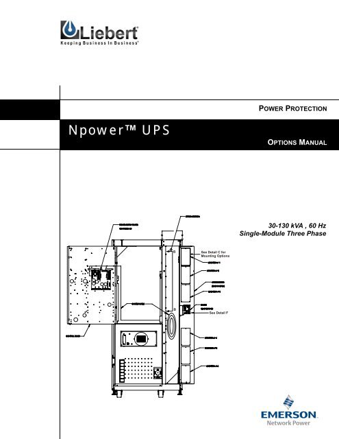
POWER PROTECTION<br />
Npower UPS<br />
OPTIONS MANUAL<br />
A<br />
A<br />
30-130 kVA , 60 Hz<br />
Single-Module Three Phase<br />
B<br />
See Detail C for<br />
Mounting Options<br />
B<br />
See Detail F
Table of Contents<br />
1.0 INTRODUCTION<br />
2.0 OPTION DESCRIPTIONS<br />
2.1 Open Comms - Discrete Output Option (OC-DO) (Programmable Relay Board) . . . . . . . . . . . . . . . . .3<br />
2.2 Open Comms – Discrete Input Option (OC-DI) (Input Contact Isolator) . . . . . . . . . . . . . . . . . . . . . . .3<br />
2.3 Option <strong>Power</strong> Supply (OPS) . . . . . . . . . . . . . . . . . . . . . . . . . . . . . . . . . . . . . . . . . . . . . . . . . . . . . . . . . .3<br />
2.4 Internal Modem . . . . . . . . . . . . . . . . . . . . . . . . . . . . . . . . . . . . . . . . . . . . . . . . . . . . . . . . . . . . . . . . . . . .3<br />
2.5 Remote Alarm Status Panel (RAS) . . . . . . . . . . . . . . . . . . . . . . . . . . . . . . . . . . . . . . . . . . . . . . . . . . . . .3<br />
2.6 Battery Circuit Breaker . . . . . . . . . . . . . . . . . . . . . . . . . . . . . . . . . . . . . . . . . . . . . . . . . . . . . . . . . . . . . .3<br />
2.7 <strong>Network</strong> Interface Card (NIC). . . . . . . . . . . . . . . . . . . . . . . . . . . . . . . . . . . . . . . . . . . . . . . . . . . . . . . . .4<br />
2.8 Multiple Battery Breaker Option. . . . . . . . . . . . . . . . . . . . . . . . . . . . . . . . . . . . . . . . . . . . . . . . . . . . . . .4<br />
2.9 AS/400 Signal Cable . . . . . . . . . . . . . . . . . . . . . . . . . . . . . . . . . . . . . . . . . . . . . . . . . . . . . . . . . . . . . . . .4<br />
2.10 AS/400 Extender Cable . . . . . . . . . . . . . . . . . . . . . . . . . . . . . . . . . . . . . . . . . . . . . . . . . . . . . . . . . . . . . .4<br />
2.11 Battery Ground Fault Detector . . . . . . . . . . . . . . . . . . . . . . . . . . . . . . . . . . . . . . . . . . . . . . . . . . . . . . . .4<br />
2.12 Auto Restart. . . . . . . . . . . . . . . . . . . . . . . . . . . . . . . . . . . . . . . . . . . . . . . . . . . . . . . . . . . . . . . . . . . . . . .4<br />
2.13 Input Trap Filter. . . . . . . . . . . . . . . . . . . . . . . . . . . . . . . . . . . . . . . . . . . . . . . . . . . . . . . . . . . . . . . . . . . .4<br />
2.14 Battery Supplement . . . . . . . . . . . . . . . . . . . . . . . . . . . . . . . . . . . . . . . . . . . . . . . . . . . . . . . . . . . . . . . . .4<br />
2.15 Battery Low Warning . . . . . . . . . . . . . . . . . . . . . . . . . . . . . . . . . . . . . . . . . . . . . . . . . . . . . . . . . . . . . . .5<br />
3.0 GENERAL INFORMATION CONCERNING 4 X 7 OPTION CARDS<br />
3.1 Option Locations and Mounting . . . . . . . . . . . . . . . . . . . . . . . . . . . . . . . . . . . . . . . . . . . . . . . . . . . . . . .6<br />
3.2 CANbus Termination. . . . . . . . . . . . . . . . . . . . . . . . . . . . . . . . . . . . . . . . . . . . . . . . . . . . . . . . . . . . . . .10<br />
4.0 GENERAL OPTION INSTALLATION INSTRUCTIONS<br />
5.0 ENABLING COMMUNICATION OPTIONS<br />
6.0 OPEN COMMS – DISCRETE OUTPUT OPTION (OC-DO) (PROGRAMMABLE RELAY BOARD)<br />
6.1 Introduction . . . . . . . . . . . . . . . . . . . . . . . . . . . . . . . . . . . . . . . . . . . . . . . . . . . . . . . . . . . . . . . . . . . . . .20<br />
6.2 Installing the OC-DO (Programmable Relay Board) . . . . . . . . . . . . . . . . . . . . . . . . . . . . . . . . . . . . . .23<br />
6.3 Programming the Open Comms – Discrete Output (OC-DO) . . . . . . . . . . . . . . . . . . . . . . . . . . . . . . .26<br />
6.3.1 Customer Alarm Interface . . . . . . . . . . . . . . . . . . . . . . . . . . . . . . . . . . . . . . . . . . . . . . . . . . . .26<br />
6.3.2 Configuring the Programmable Relay Boards . . . . . . . . . . . . . . . . . . . . . . . . . . . . . . . . . . . . .27<br />
6.4 Configuring the Programmable Relay Option to support an AS/400 Shutdown . . . . . . . . . . . . . . . . .30<br />
6.5 Configuring the Programmable Relay Option to support a Standard Set . . . . . . . . . . . . . . . . . . . . . . .33<br />
7.0 OPEN COMMS – DISCRETE INPUT OPTION (OC-DI) (INPUT CONTACT ISOLATOR)<br />
7.1 Introduction . . . . . . . . . . . . . . . . . . . . . . . . . . . . . . . . . . . . . . . . . . . . . . . . . . . . . . . . . . . . . . . . . . . . . .34<br />
i
7.2 Installation . . . . . . . . . . . . . . . . . . . . . . . . . . . . . . . . . . . . . . . . . . . . . . . . . . . . . . . . . . . . . . . . . . . . . . 34<br />
7.3 Programming the OC-DI (Input Contact Isolator Option). . . . . . . . . . . . . . . . . . . . . . . . . . . . . . . . . . 37<br />
8.0 OPTION POWER SUPPLY<br />
8.1 Installation . . . . . . . . . . . . . . . . . . . . . . . . . . . . . . . . . . . . . . . . . . . . . . . . . . . . . . . . . . . . . . . . . . . . . . 40<br />
9.0 REMOTE ALARM STATUS PANEL (RAS)<br />
9.1 Introduction . . . . . . . . . . . . . . . . . . . . . . . . . . . . . . . . . . . . . . . . . . . . . . . . . . . . . . . . . . . . . . . . . . . . . 45<br />
9.2 Installing the Remote Alarm Status Panel . . . . . . . . . . . . . . . . . . . . . . . . . . . . . . . . . . . . . . . . . . . . . . 48<br />
9.3 Interpreting the LED indicators . . . . . . . . . . . . . . . . . . . . . . . . . . . . . . . . . . . . . . . . . . . . . . . . . . . . . . 51<br />
9.4 The Lamp Test/Reset Push button . . . . . . . . . . . . . . . . . . . . . . . . . . . . . . . . . . . . . . . . . . . . . . . . . . . . 51<br />
9.5 Audio Reset Push button . . . . . . . . . . . . . . . . . . . . . . . . . . . . . . . . . . . . . . . . . . . . . . . . . . . . . . . . . . . 51<br />
10.0 INTERNAL MODEM<br />
10.1 Introduction . . . . . . . . . . . . . . . . . . . . . . . . . . . . . . . . . . . . . . . . . . . . . . . . . . . . . . . . . . . . . . . . . . . . . 52<br />
10.2 Installing the Internal Modem Option . . . . . . . . . . . . . . . . . . . . . . . . . . . . . . . . . . . . . . . . . . . . . . . . . 52<br />
10.3 Installation Instructions for the Internal Modem . . . . . . . . . . . . . . . . . . . . . . . . . . . . . . . . . . . . . . . . . 55<br />
10.4 Operating Instructions . . . . . . . . . . . . . . . . . . . . . . . . . . . . . . . . . . . . . . . . . . . . . . . . . . . . . . . . . . . . . 55<br />
10.4.1 Configuring the Modem to Accept Incoming Calls . . . . . . . . . . . . . . . . . . . . . . . . . . . . . . . . 59<br />
10.4.2 Using the Modem for Outgoing Calls. . . . . . . . . . . . . . . . . . . . . . . . . . . . . . . . . . . . . . . . . . . 63<br />
11.0 SITESCAN INTERFACE<br />
12.0 EXTERNAL MODEM<br />
12.1 Installation . . . . . . . . . . . . . . . . . . . . . . . . . . . . . . . . . . . . . . . . . . . . . . . . . . . . . . . . . . . . . . . . . . . . . . 65<br />
12.2 Modem Operation . . . . . . . . . . . . . . . . . . . . . . . . . . . . . . . . . . . . . . . . . . . . . . . . . . . . . . . . . . . . . . . . 65<br />
12.3 Dial Out Pager . . . . . . . . . . . . . . . . . . . . . . . . . . . . . . . . . . . . . . . . . . . . . . . . . . . . . . . . . . . . . . . . . . . 65<br />
13.0 RS 232 PORT<br />
13.1 Installation . . . . . . . . . . . . . . . . . . . . . . . . . . . . . . . . . . . . . . . . . . . . . . . . . . . . . . . . . . . . . . . . . . . . . . 68<br />
13.2 ASCII Terminal Operation. . . . . . . . . . . . . . . . . . . . . . . . . . . . . . . . . . . . . . . . . . . . . . . . . . . . . . . . . . 68<br />
14.0 MULTIPLE BATTERY BREAKER OPTION<br />
14.1 MBB Board . . . . . . . . . . . . . . . . . . . . . . . . . . . . . . . . . . . . . . . . . . . . . . . . . . . . . . . . . . . . . . . . . . . . . 70<br />
14.1.1 Kit Contents and Tools . . . . . . . . . . . . . . . . . . . . . . . . . . . . . . . . . . . . . . . . . . . . . . . . . . . . . . 70<br />
14.1.2 Installation and Wiring . . . . . . . . . . . . . . . . . . . . . . . . . . . . . . . . . . . . . . . . . . . . . . . . . . . . . . 71<br />
14.1.3 Wiring . . . . . . . . . . . . . . . . . . . . . . . . . . . . . . . . . . . . . . . . . . . . . . . . . . . . . . . . . . . . . . . . . . . 73<br />
14.1.4 Testing of MBB Board . . . . . . . . . . . . . . . . . . . . . . . . . . . . . . . . . . . . . . . . . . . . . . . . . . . . . . 73<br />
14.2 Input Contact Isolator (ICI or OC-DI) Board . . . . . . . . . . . . . . . . . . . . . . . . . . . . . . . . . . . . . . . . . . . 74<br />
14.2.1 Installation. . . . . . . . . . . . . . . . . . . . . . . . . . . . . . . . . . . . . . . . . . . . . . . . . . . . . . . . . . . . . . . . 74<br />
14.2.2 Wiring . . . . . . . . . . . . . . . . . . . . . . . . . . . . . . . . . . . . . . . . . . . . . . . . . . . . . . . . . . . . . . . . . . . 74<br />
14.2.3 Testing of ICI Board . . . . . . . . . . . . . . . . . . . . . . . . . . . . . . . . . . . . . . . . . . . . . . . . . . . . . . . . 76<br />
ii
14.2.4 Setting Number of Battery Cabinets. . . . . . . . . . . . . . . . . . . . . . . . . . . . . . . . . . . . . . . . . . . . .76<br />
14.2.5 Alarms . . . . . . . . . . . . . . . . . . . . . . . . . . . . . . . . . . . . . . . . . . . . . . . . . . . . . . . . . . . . . . . . . . .76<br />
15.0 OPEN COMMS – NETWORK INTERFACE CARD (NIC)<br />
15.1 Introduction . . . . . . . . . . . . . . . . . . . . . . . . . . . . . . . . . . . . . . . . . . . . . . . . . . . . . . . . . . . . . . . . . . . . . .77<br />
15.2 Specifications. . . . . . . . . . . . . . . . . . . . . . . . . . . . . . . . . . . . . . . . . . . . . . . . . . . . . . . . . . . . . . . . . . . . .77<br />
15.3 Installation . . . . . . . . . . . . . . . . . . . . . . . . . . . . . . . . . . . . . . . . . . . . . . . . . . . . . . . . . . . . . . . . . . . . . . .78<br />
15.4 User Connections. . . . . . . . . . . . . . . . . . . . . . . . . . . . . . . . . . . . . . . . . . . . . . . . . . . . . . . . . . . . . . . . . .81<br />
15.5 System Configuration - <strong>Network</strong> Interface Card. . . . . . . . . . . . . . . . . . . . . . . . . . . . . . . . . . . . . . . . . .81<br />
15.5.1 Dip Switch Settings . . . . . . . . . . . . . . . . . . . . . . . . . . . . . . . . . . . . . . . . . . . . . . . . . . . . . . . . .81<br />
15.5.2 Enabling the NIC Option . . . . . . . . . . . . . . . . . . . . . . . . . . . . . . . . . . . . . . . . . . . . . . . . . . . . .81<br />
15.5.3 Configuring the NIC on a Service Terminal (External Computer) . . . . . . . . . . . . . . . . . . . . .82<br />
15.6 Operation of the NIC Option. . . . . . . . . . . . . . . . . . . . . . . . . . . . . . . . . . . . . . . . . . . . . . . . . . . . . . . . .85<br />
15.6.1 SNMP . . . . . . . . . . . . . . . . . . . . . . . . . . . . . . . . . . . . . . . . . . . . . . . . . . . . . . . . . . . . . . . . . . . .85<br />
15.6.2 MIB. . . . . . . . . . . . . . . . . . . . . . . . . . . . . . . . . . . . . . . . . . . . . . . . . . . . . . . . . . . . . . . . . . . . . .86<br />
15.6.3 HTTP . . . . . . . . . . . . . . . . . . . . . . . . . . . . . . . . . . . . . . . . . . . . . . . . . . . . . . . . . . . . . . . . . . . .86<br />
15.6.4 Modbus RTU . . . . . . . . . . . . . . . . . . . . . . . . . . . . . . . . . . . . . . . . . . . . . . . . . . . . . . . . . . . . . .93<br />
15.6.5 System Reset . . . . . . . . . . . . . . . . . . . . . . . . . . . . . . . . . . . . . . . . . . . . . . . . . . . . . . . . . . . . . .93<br />
15.6.6 Diagnostics . . . . . . . . . . . . . . . . . . . . . . . . . . . . . . . . . . . . . . . . . . . . . . . . . . . . . . . . . . . . . . . .94<br />
15.7 Modbus Communications and Connectivity . . . . . . . . . . . . . . . . . . . . . . . . . . . . . . . . . . . . . . . . . . . . .95<br />
15.7.1 Implementation Basics . . . . . . . . . . . . . . . . . . . . . . . . . . . . . . . . . . . . . . . . . . . . . . . . . . . . . . .95<br />
15.7.2 Constraints . . . . . . . . . . . . . . . . . . . . . . . . . . . . . . . . . . . . . . . . . . . . . . . . . . . . . . . . . . . . . . . .95<br />
15.7.3 Transmission Format . . . . . . . . . . . . . . . . . . . . . . . . . . . . . . . . . . . . . . . . . . . . . . . . . . . . . . . .96<br />
15.7.4 Physical Connection . . . . . . . . . . . . . . . . . . . . . . . . . . . . . . . . . . . . . . . . . . . . . . . . . . . . . . . . .96<br />
15.7.5 Modbus Slave Functions . . . . . . . . . . . . . . . . . . . . . . . . . . . . . . . . . . . . . . . . . . . . . . . . . . . . .97<br />
15.8 NIC Setup and Testing. . . . . . . . . . . . . . . . . . . . . . . . . . . . . . . . . . . . . . . . . . . . . . . . . . . . . . . . . . . . .100<br />
15.8.1 Jumper Placements . . . . . . . . . . . . . . . . . . . . . . . . . . . . . . . . . . . . . . . . . . . . . . . . . . . . . . . . .100<br />
15.8.2 Testing the <strong>Network</strong> . . . . . . . . . . . . . . . . . . . . . . . . . . . . . . . . . . . . . . . . . . . . . . . . . . . . . . . .101<br />
15.8.3 Service Terminal Troubleshooting . . . . . . . . . . . . . . . . . . . . . . . . . . . . . . . . . . . . . . . . . . . . .101<br />
15.8.4 SNMP Troubleshooting . . . . . . . . . . . . . . . . . . . . . . . . . . . . . . . . . . . . . . . . . . . . . . . . . . . . .101<br />
15.8.5 Web Troubleshooting . . . . . . . . . . . . . . . . . . . . . . . . . . . . . . . . . . . . . . . . . . . . . . . . . . . . . . .101<br />
15.8.6 Modbus Troubleshooting . . . . . . . . . . . . . . . . . . . . . . . . . . . . . . . . . . . . . . . . . . . . . . . . . . . .102<br />
16.0 DC GROUND FAULT DETECTOR<br />
16.1 Introduction . . . . . . . . . . . . . . . . . . . . . . . . . . . . . . . . . . . . . . . . . . . . . . . . . . . . . . . . . . . . . . . . . . . . .103<br />
16.2 Installing the DC Ground Fault Detector . . . . . . . . . . . . . . . . . . . . . . . . . . . . . . . . . . . . . . . . . . . . . .103<br />
16.2.1 Field Installation: . . . . . . . . . . . . . . . . . . . . . . . . . . . . . . . . . . . . . . . . . . . . . . . . . . . . . . . . . .103<br />
16.2.2 Installation Procedure. . . . . . . . . . . . . . . . . . . . . . . . . . . . . . . . . . . . . . . . . . . . . . . . . . . . . . .104<br />
17.0 AUTO RESTART<br />
18.0 LOAD BUS SYNC<br />
18.1 System Description . . . . . . . . . . . . . . . . . . . . . . . . . . . . . . . . . . . . . . . . . . . . . . . . . . . . . . . . . . . . . . .111<br />
iii
18.2 General Description . . . . . . . . . . . . . . . . . . . . . . . . . . . . . . . . . . . . . . . . . . . . . . . . . . . . . . . . . . . . . . 111<br />
18.3 System Operation. . . . . . . . . . . . . . . . . . . . . . . . . . . . . . . . . . . . . . . . . . . . . . . . . . . . . . . . . . . . . . . . 112<br />
18.4 Load Bus Sync (LBS) Installation . . . . . . . . . . . . . . . . . . . . . . . . . . . . . . . . . . . . . . . . . . . . . . . . . . . 112<br />
18.4.1 Mechanical Installation of LBS Controller. . . . . . . . . . . . . . . . . . . . . . . . . . . . . . . . . . . . . . 113<br />
18.4.2 LBS Interface Option Installation Procedure . . . . . . . . . . . . . . . . . . . . . . . . . . . . . . . . . . . . 116<br />
18.4.3 LBS Wiring (Npower to Npower). . . . . . . . . . . . . . . . . . . . . . . . . . . . . . . . . . . . . . . . . . . . . 120<br />
18.4.4 LBS Wiring (Npower to Series 300). . . . . . . . . . . . . . . . . . . . . . . . . . . . . . . . . . . . . . . . . . . 120<br />
18.4.5 LBS Wiring (Npower to Series 600T) . . . . . . . . . . . . . . . . . . . . . . . . . . . . . . . . . . . . . . . . . 120<br />
18.4.6 LBS Option Enable Procedure . . . . . . . . . . . . . . . . . . . . . . . . . . . . . . . . . . . . . . . . . . . . . . . 123<br />
18.5 Operator Controls. . . . . . . . . . . . . . . . . . . . . . . . . . . . . . . . . . . . . . . . . . . . . . . . . . . . . . . . . . . . . . . . 123<br />
19.0 INPUT TRAP FILTER<br />
20.0 APPENDIX<br />
iv
List of Figures<br />
Figure 1 Npower Option Locations . . . . . . . . . . . . . . . . . . . . . . . . . . . . . . . . . . . . . . . . . . . . . . . . . . . . . . . . . . . . . . . .7<br />
Figure 2 Detail F and View B-B . . . . . . . . . . . . . . . . . . . . . . . . . . . . . . . . . . . . . . . . . . . . . . . . . . . . . . . . . . . . . . . . . . .8<br />
Figure 3 Option Location and Mounting Detail . . . . . . . . . . . . . . . . . . . . . . . . . . . . . . . . . . . . . . . . . . . . . . . . . . . . . . .9<br />
Figure 4 Diagram of a Basic Npower Without Options . . . . . . . . . . . . . . . . . . . . . . . . . . . . . . . . . . . . . . . . . . . . . . . .10<br />
Figure 5 Diagram of Npower with OPS and RAS Added . . . . . . . . . . . . . . . . . . . . . . . . . . . . . . . . . . . . . . . . . . . . . .11<br />
Figure 6 Diagram of Npower with Additional RAS Panel . . . . . . . . . . . . . . . . . . . . . . . . . . . . . . . . . . . . . . . . . . . . .12<br />
Figure 7 Diagram of Npower with Additional Options . . . . . . . . . . . . . . . . . . . . . . . . . . . . . . . . . . . . . . . . . . . . . . . .12<br />
Figure 8 Diagram of Npower with One or More Options Installed, and an OPS is not Installed . . . . . . . . . . . . . . . .13<br />
Figure 9 Jumper Removal. . . . . . . . . . . . . . . . . . . . . . . . . . . . . . . . . . . . . . . . . . . . . . . . . . . . . . . . . . . . . . . . . . . . . . .13<br />
Figure 10 Typical CANbus Connections . . . . . . . . . . . . . . . . . . . . . . . . . . . . . . . . . . . . . . . . . . . . . . . . . . . . . . . . . . . .15<br />
Figure 11 Operator Control Panel. . . . . . . . . . . . . . . . . . . . . . . . . . . . . . . . . . . . . . . . . . . . . . . . . . . . . . . . . . . . . . . . . .16<br />
Figure 12 Main Menu Screen . . . . . . . . . . . . . . . . . . . . . . . . . . . . . . . . . . . . . . . . . . . . . . . . . . . . . . . . . . . . . . . . . . . . .17<br />
Figure 13 Configuration Screen . . . . . . . . . . . . . . . . . . . . . . . . . . . . . . . . . . . . . . . . . . . . . . . . . . . . . . . . . . . . . . . . . . .17<br />
Figure 14 Systems Settings Screen. . . . . . . . . . . . . . . . . . . . . . . . . . . . . . . . . . . . . . . . . . . . . . . . . . . . . . . . . . . . . . . . .17<br />
Figure 15 System Settings Screen with COMM OPTIONS highlighted . . . . . . . . . . . . . . . . . . . . . . . . . . . . . . . . . . . .18<br />
Figure 16 Communications Options Screen . . . . . . . . . . . . . . . . . . . . . . . . . . . . . . . . . . . . . . . . . . . . . . . . . . . . . . . . . .18<br />
Figure 17 Password Screen. . . . . . . . . . . . . . . . . . . . . . . . . . . . . . . . . . . . . . . . . . . . . . . . . . . . . . . . . . . . . . . . . . . . . . .18<br />
Figure 18 Programmable Relay Screen . . . . . . . . . . . . . . . . . . . . . . . . . . . . . . . . . . . . . . . . . . . . . . . . . . . . . . . . . . . . .19<br />
Figure 19 OC-DO as the First Option. . . . . . . . . . . . . . . . . . . . . . . . . . . . . . . . . . . . . . . . . . . . . . . . . . . . . . . . . . . . . . .21<br />
Figure 20 Installing OC-DO with a Pre-Installed Option. . . . . . . . . . . . . . . . . . . . . . . . . . . . . . . . . . . . . . . . . . . . . . . .22<br />
Figure 21 Customer Connections . . . . . . . . . . . . . . . . . . . . . . . . . . . . . . . . . . . . . . . . . . . . . . . . . . . . . . . . . . . . . . . . . .24<br />
Figure 22 Customer Alarm Interface Screen . . . . . . . . . . . . . . . . . . . . . . . . . . . . . . . . . . . . . . . . . . . . . . . . . . . . . . . . .26<br />
Figure 23 Customer Alarm Interface Screen, page 2 . . . . . . . . . . . . . . . . . . . . . . . . . . . . . . . . . . . . . . . . . . . . . . . . . . .27<br />
Figure 24 Programmable Output Relay Board #1, AS400 Assignment . . . . . . . . . . . . . . . . . . . . . . . . . . . . . . . . . . . .27<br />
Figure 25 Relay Assignments . . . . . . . . . . . . . . . . . . . . . . . . . . . . . . . . . . . . . . . . . . . . . . . . . . . . . . . . . . . . . . . . . . . . .27<br />
Figure 26 Programmable Output Relay Board, Std. Set. . . . . . . . . . . . . . . . . . . . . . . . . . . . . . . . . . . . . . . . . . . . . . . . .28<br />
Figure 27 Programmable Output Relay Board, Std. Set, page 2 . . . . . . . . . . . . . . . . . . . . . . . . . . . . . . . . . . . . . . . . . .28<br />
Figure 28 Programmable Output Relay Board, User Defined . . . . . . . . . . . . . . . . . . . . . . . . . . . . . . . . . . . . . . . . . . . .28<br />
Figure 29 List of Alarm Faults Screen . . . . . . . . . . . . . . . . . . . . . . . . . . . . . . . . . . . . . . . . . . . . . . . . . . . . . . . . . . . . . .29<br />
Figure 30 Configuration of the AS/400 System. . . . . . . . . . . . . . . . . . . . . . . . . . . . . . . . . . . . . . . . . . . . . . . . . . . . . . .32<br />
Figure 31 Wire Routing for OC-DI. . . . . . . . . . . . . . . . . . . . . . . . . . . . . . . . . . . . . . . . . . . . . . . . . . . . . . . . . . . . . . . . .35<br />
Figure 32 Customer Hookups for ICI . . . . . . . . . . . . . . . . . . . . . . . . . . . . . . . . . . . . . . . . . . . . . . . . . . . . . . . . . . . . . . .36<br />
Figure 33 Alarm / Fault Name Screen . . . . . . . . . . . . . . . . . . . . . . . . . . . . . . . . . . . . . . . . . . . . . . . . . . . . . . . . . . . . . .37<br />
Figure 34 Set Alarm Parameters Screen . . . . . . . . . . . . . . . . . . . . . . . . . . . . . . . . . . . . . . . . . . . . . . . . . . . . . . . . . . . . .38<br />
Figure 35 Set Delay Time Screen . . . . . . . . . . . . . . . . . . . . . . . . . . . . . . . . . . . . . . . . . . . . . . . . . . . . . . . . . . . . . . . . . .38<br />
Figure 36 Contact Signal Assignment Screen . . . . . . . . . . . . . . . . . . . . . . . . . . . . . . . . . . . . . . . . . . . . . . . . . . . . . . . .39<br />
Figure 37 OPS Installation . . . . . . . . . . . . . . . . . . . . . . . . . . . . . . . . . . . . . . . . . . . . . . . . . . . . . . . . . . . . . . . . . . . . . . .41<br />
Figure 38 OPS Location and Details . . . . . . . . . . . . . . . . . . . . . . . . . . . . . . . . . . . . . . . . . . . . . . . . . . . . . . . . . . . . . . .42<br />
Figure 39 Customer Connections . . . . . . . . . . . . . . . . . . . . . . . . . . . . . . . . . . . . . . . . . . . . . . . . . . . . . . . . . . . . . . . . . .43<br />
Figure 40 Remote Alarm Status Panel Base and Cover . . . . . . . . . . . . . . . . . . . . . . . . . . . . . . . . . . . . . . . . . . . . . . . . .46<br />
Figure 41 RAS Details B and C . . . . . . . . . . . . . . . . . . . . . . . . . . . . . . . . . . . . . . . . . . . . . . . . . . . . . . . . . . . . . . . . . . .47<br />
Figure 42 RAS Detail D . . . . . . . . . . . . . . . . . . . . . . . . . . . . . . . . . . . . . . . . . . . . . . . . . . . . . . . . . . . . . . . . . . . . . . . . .47<br />
Figure 43 RAS Configuration Options . . . . . . . . . . . . . . . . . . . . . . . . . . . . . . . . . . . . . . . . . . . . . . . . . . . . . . . . . . . . . .50<br />
Figure 44 Installation of the Internal Modem. . . . . . . . . . . . . . . . . . . . . . . . . . . . . . . . . . . . . . . . . . . . . . . . . . . . . . . . .53<br />
Figure 45 Micro Monitor Board . . . . . . . . . . . . . . . . . . . . . . . . . . . . . . . . . . . . . . . . . . . . . . . . . . . . . . . . . . . . . . . . . . .54<br />
Figure 46 Internal Connections. . . . . . . . . . . . . . . . . . . . . . . . . . . . . . . . . . . . . . . . . . . . . . . . . . . . . . . . . . . . . . . . . . . .54<br />
Figure 47 Communication Options Screen. . . . . . . . . . . . . . . . . . . . . . . . . . . . . . . . . . . . . . . . . . . . . . . . . . . . . . . . . . .56<br />
Figure 48 Auto Dial Screen . . . . . . . . . . . . . . . . . . . . . . . . . . . . . . . . . . . . . . . . . . . . . . . . . . . . . . . . . . . . . . . . . . . . . .56<br />
Figure 49 Modem Selection Screen . . . . . . . . . . . . . . . . . . . . . . . . . . . . . . . . . . . . . . . . . . . . . . . . . . . . . . . . . . . . . . . .56<br />
v
Figure 50 Dial Out Phone Number Screen . . . . . . . . . . . . . . . . . . . . . . . . . . . . . . . . . . . . . . . . . . . . . . . . . . . . . . . . . . 57<br />
Figure 51 Auto Dial Screen, Second Page. . . . . . . . . . . . . . . . . . . . . . . . . . . . . . . . . . . . . . . . . . . . . . . . . . . . . . . . . . . 58<br />
Figure 52 Pager Support Screen. . . . . . . . . . . . . . . . . . . . . . . . . . . . . . . . . . . . . . . . . . . . . . . . . . . . . . . . . . . . . . . . . . . 66<br />
Figure 53 Multiple Battery Breaker Board Mounting Position . . . . . . . . . . . . . . . . . . . . . . . . . . . . . . . . . . . . . . . . . . . 72<br />
Figure 54 Schematic Diagram with Option Installed. . . . . . . . . . . . . . . . . . . . . . . . . . . . . . . . . . . . . . . . . . . . . . . . . . . 73<br />
Figure 55 Six Battery Cabinets Wiring Diagram. . . . . . . . . . . . . . . . . . . . . . . . . . . . . . . . . . . . . . . . . . . . . . . . . . . . . . 75<br />
Figure 56 Set Number of Battery Cabinets Screen . . . . . . . . . . . . . . . . . . . . . . . . . . . . . . . . . . . . . . . . . . . . . . . . . . . . 76<br />
Figure 57 Installing the NIC Option . . . . . . . . . . . . . . . . . . . . . . . . . . . . . . . . . . . . . . . . . . . . . . . . . . . . . . . . . . . . . . . 79<br />
Figure 58 Installing the NIC Option (Details) . . . . . . . . . . . . . . . . . . . . . . . . . . . . . . . . . . . . . . . . . . . . . . . . . . . . . . . . 80<br />
Figure 59 Communications Options, page 2 . . . . . . . . . . . . . . . . . . . . . . . . . . . . . . . . . . . . . . . . . . . . . . . . . . . . . . . . . 81<br />
Figure 60 NIC Configuration Menu Screen. . . . . . . . . . . . . . . . . . . . . . . . . . . . . . . . . . . . . . . . . . . . . . . . . . . . . . . . . . 83<br />
Figure 61 HTTP Home Page . . . . . . . . . . . . . . . . . . . . . . . . . . . . . . . . . . . . . . . . . . . . . . . . . . . . . . . . . . . . . . . . . . . . . 87<br />
Figure 62 HTTP Active Alarms screen . . . . . . . . . . . . . . . . . . . . . . . . . . . . . . . . . . . . . . . . . . . . . . . . . . . . . . . . . . . . . 88<br />
Figure 63 HTTP Bypass Screen. . . . . . . . . . . . . . . . . . . . . . . . . . . . . . . . . . . . . . . . . . . . . . . . . . . . . . . . . . . . . . . . . . . 88<br />
Figure 64 HTTP Input Screen. . . . . . . . . . . . . . . . . . . . . . . . . . . . . . . . . . . . . . . . . . . . . . . . . . . . . . . . . . . . . . . . . . . . 89<br />
Figure 65 HTTP Static Switch Screen . . . . . . . . . . . . . . . . . . . . . . . . . . . . . . . . . . . . . . . . . . . . . . . . . . . . . . . . . . . . . . 89<br />
Figure 66 HTTP Battery Screen. . . . . . . . . . . . . . . . . . . . . . . . . . . . . . . . . . . . . . . . . . . . . . . . . . . . . . . . . . . . . . . . . . . 90<br />
Figure 67 HTTP Rectifier Screen . . . . . . . . . . . . . . . . . . . . . . . . . . . . . . . . . . . . . . . . . . . . . . . . . . . . . . . . . . . . . . . . . 90<br />
Figure 68 HTTP Inverter Screen . . . . . . . . . . . . . . . . . . . . . . . . . . . . . . . . . . . . . . . . . . . . . . . . . . . . . . . . . . . . . . . . . . 91<br />
Figure 69 HTTP Load Screen . . . . . . . . . . . . . . . . . . . . . . . . . . . . . . . . . . . . . . . . . . . . . . . . . . . . . . . . . . . . . . . . . . . . 92<br />
Figure 70 HTTP “Other” Alarms Screen. . . . . . . . . . . . . . . . . . . . . . . . . . . . . . . . . . . . . . . . . . . . . . . . . . . . . . . . . . . . 93<br />
Figure 71 LED Locations. . . . . . . . . . . . . . . . . . . . . . . . . . . . . . . . . . . . . . . . . . . . . . . . . . . . . . . . . . . . . . . . . . . . . . . . 95<br />
Figure 72 Typical Maximum Installation. . . . . . . . . . . . . . . . . . . . . . . . . . . . . . . . . . . . . . . . . . . . . . . . . . . . . . . . . . . . 96<br />
Figure 73 Installation Exceeding Maximum Specifications . . . . . . . . . . . . . . . . . . . . . . . . . . . . . . . . . . . . . . . . . . . . . 97<br />
Figure 74 Npower UPS 100/130 KVA Front and Side Views . . . . . . . . . . . . . . . . . . . . . . . . . . . . . . . . . . . . . . . . . . . 105<br />
Figure 75 Npower UPS 80 - 130 KVA. . . . . . . . . . . . . . . . . . . . . . . . . . . . . . . . . . . . . . . . . . . . . . . . . . . . . . . . . . . . . 106<br />
Figure 76 Wiring Diagram for Battery Ground Fault Option . . . . . . . . . . . . . . . . . . . . . . . . . . . . . . . . . . . . . . . . . . . 107<br />
Figure 77 DC Ground Fault Wiring Connections . . . . . . . . . . . . . . . . . . . . . . . . . . . . . . . . . . . . . . . . . . . . . . . . . . . . 108<br />
Figure 78 Auto Restart Fuse Kit . . . . . . . . . . . . . . . . . . . . . . . . . . . . . . . . . . . . . . . . . . . . . . . . . . . . . . . . . . . . . . . . . 110<br />
Figure 79 Load Bus Sync (LBS) Control Panel. . . . . . . . . . . . . . . . . . . . . . . . . . . . . . . . . . . . . . . . . . . . . . . . . . . . . . 111<br />
Figure 80 LBS Mechanical Installation . . . . . . . . . . . . . . . . . . . . . . . . . . . . . . . . . . . . . . . . . . . . . . . . . . . . . . . . . . . . 113<br />
Figure 81 LBS Block Diagram . . . . . . . . . . . . . . . . . . . . . . . . . . . . . . . . . . . . . . . . . . . . . . . . . . . . . . . . . . . . . . . . . . 114<br />
Figure 82 LBS Assembly Diagram . . . . . . . . . . . . . . . . . . . . . . . . . . . . . . . . . . . . . . . . . . . . . . . . . . . . . . . . . . . . . . . 115<br />
Figure 83 Details of Connection to Terminal Block . . . . . . . . . . . . . . . . . . . . . . . . . . . . . . . . . . . . . . . . . . . . . . . . . . 116<br />
Figure 84 LBS Npower to Npower Wiring without Transformer Cabinet . . . . . . . . . . . . . . . . . . . . . . . . . . . . . . . . . 121<br />
Figure 85 LBS Npower to Npower Wiring with Transformer Cabinet . . . . . . . . . . . . . . . . . . . . . . . . . . . . . . . . . . . . 122<br />
Figure 86 10% Passive Filter Settings Screen . . . . . . . . . . . . . . . . . . . . . . . . . . . . . . . . . . . . . . . . . . . . . . . . . . . . . . . 125
List of Tables<br />
Table 1 Locations and Part Numbers . . . . . . . . . . . . . . . . . . . . . . . . . . . . . . . . . . . . . . . . . . . . . . . . . . . . . . . . . . . . . .6<br />
Table 2 Tabulation Contacts . . . . . . . . . . . . . . . . . . . . . . . . . . . . . . . . . . . . . . . . . . . . . . . . . . . . . . . . . . . . . . . . . . . .25<br />
Table 3 OC-DO Configuration for AS400 . . . . . . . . . . . . . . . . . . . . . . . . . . . . . . . . . . . . . . . . . . . . . . . . . . . . . . . . .30<br />
Table 4 Wire and Program Configuration . . . . . . . . . . . . . . . . . . . . . . . . . . . . . . . . . . . . . . . . . . . . . . . . . . . . . . . . .33<br />
Table 5 Remote Alarm Status Panel Wiring . . . . . . . . . . . . . . . . . . . . . . . . . . . . . . . . . . . . . . . . . . . . . . . . . . . . . . . .48<br />
Table 6 Remote Alarm Status DIP Switch Settings . . . . . . . . . . . . . . . . . . . . . . . . . . . . . . . . . . . . . . . . . . . . . . . . . .49<br />
Table 7 Service Terminal Commands . . . . . . . . . . . . . . . . . . . . . . . . . . . . . . . . . . . . . . . . . . . . . . . . . . . . . . . . . . . . .60<br />
Table 8 Connections to ICI Board. . . . . . . . . . . . . . . . . . . . . . . . . . . . . . . . . . . . . . . . . . . . . . . . . . . . . . . . . . . . . . . .69<br />
Table 9 Field Installation Kit, Contents. . . . . . . . . . . . . . . . . . . . . . . . . . . . . . . . . . . . . . . . . . . . . . . . . . . . . . . . . . . .70<br />
Table 10 LED Identifiers. . . . . . . . . . . . . . . . . . . . . . . . . . . . . . . . . . . . . . . . . . . . . . . . . . . . . . . . . . . . . . . . . . . . . . . .94<br />
Table 11 Exception Response . . . . . . . . . . . . . . . . . . . . . . . . . . . . . . . . . . . . . . . . . . . . . . . . . . . . . . . . . . . . . . . . . . . .99<br />
Table 12 Program Jumper Selection . . . . . . . . . . . . . . . . . . . . . . . . . . . . . . . . . . . . . . . . . . . . . . . . . . . . . . . . . . . . . .108<br />
Table 13 Selections . . . . . . . . . . . . . . . . . . . . . . . . . . . . . . . . . . . . . . . . . . . . . . . . . . . . . . . . . . . . . . . . . . . . . . . . . . .109<br />
Table 14 Alarms, Functions, and Corrective Actions . . . . . . . . . . . . . . . . . . . . . . . . . . . . . . . . . . . . . . . . . . . . . . . . .126<br />
vii
IMPORTANT SAFETY INSTRUCTIONS<br />
Save These Instructions.<br />
This manual contains important safety instructions that should be followed during installation and maintenance<br />
of the options packages for the Npower UPS. Before the installer begins the installation process for any option,<br />
we recommend that he read through the safety precautions and the option installation instructions, taking all necessary<br />
safety precautions to protect himself and the equipment he will be installing.<br />
!<br />
WARNING<br />
LETHAL VOLTAGES MAY BE PRESENT WITHIN THIS UNIT EVEN<br />
WHEN IT IS APPARENTLY NOT OPERATING. OBSERVE ALL<br />
CAUTIONS AND WARNINGS IN THIS MANUAL. FAILURE TO DO SO<br />
COULD RESULT IN SERIOUS INJURY OR DEATH.<br />
REFER UNIT TO QUALIFIED SERVICE PERSONNEL IF MAINTENANCE<br />
IS REQUIRED. NO ONE SHOULD WORK ON THIS EQUIPMENT UNLESS<br />
HE IS FULLY QUALIFIED TO DO SO. AN INSTALLER SHOULD NEVER<br />
WORK ALONE.<br />
!<br />
WARNING<br />
WHEN INSTALLING OPTIONS IN AN NPOWER UPS ALWAYS PUT THE<br />
UNIT ON MAINTENANCE BYPASS AND OPEN THE BATTERY CIRCUIT<br />
BREAKER. INSTRUCTIONS ON HOW TO DO THIS ARE IN THE<br />
FOLLOWING SECTIONS.<br />
!<br />
WARNING<br />
WHEN REMOVING POWER FROM THE UPS, ALLOW FIVE MINUTES<br />
FOR CAPACITORS TO DISCHARGE BEFORE WORKING ON THE<br />
EQUIPMENT.<br />
!<br />
CAUTION<br />
This equipment complies with the requirements in Part 15 of <strong>FC</strong>C rules for a<br />
Class A computing device. Operation of this equipment in a residential area may<br />
cause interference to radio and TV reception, requiring the operator to take<br />
whatever steps are necessary to correct the interference.<br />
!<br />
CAUTION<br />
Do not put option control wiring in the same conduit as the UPS input or output<br />
power cables.<br />
1
1.0 INTRODUCTION<br />
The Liebert Npower Uninterruptible <strong>Power</strong> System (UPS) protects valuable equipment, data, and processes from<br />
the consequences of disturbances in the utility power source. To enhance the flexibility and performance of the<br />
Npower UPS, Liebert offers several features and options that can be ordered as standard equipment or purchased<br />
separately and field-installed by a qualified Liebert Customer Service and Support technician or distributor. This<br />
manual describes the options available for the UPS and gives detailed installation and operating instructions for<br />
each.<br />
NOTE<br />
It will be helpful to have the Npower Operation and Maintenance Manual<br />
available during the installation process, as it contains information referred to<br />
here.<br />
2 Introduction
2.0 OPTION DESCRIPTIONS<br />
The NpowerUPS features an Option Door that covers the UPS input and output connection section. The general<br />
layout of the UPS and Option Door is shown in the illustration on the cover of this manual. With a few exceptions,<br />
most of the following options are installed on or near the Option Door. The required hardware and cabling<br />
to attach the boards to the UPS system are included. Additional cables and wiring required to connect to the customer’s<br />
equipment outside the UPS are to be supplied by others.<br />
2.1 Open Comms - Discrete Output Option (OC-DO) (Programmable Relay Board)<br />
The Npower UPS offers a Programmable Relay Board option allowing the Operator to program certain alarms or<br />
events to activate single or multiple output relays. In addition to the user-defined programming capability of the<br />
system, the Npower offers two pre-defined relay assignments: AS400, where only the first 3 relay assignments<br />
are pre configured (with the other 5 assignments available for user definition, and Standard Set, where the first 7<br />
relays are assigned with the remaining one left unprogrammed. (The 8th assignment is not available for user definition.)<br />
Programming of the output relays is performed through the LCD display of the UPS unit. Each relay output has<br />
two sets of Form-C dry contacts rated for 1 Amp @ 30 VDC or 250 mAmps @ 125 VAC.<br />
2.2 Open Comms – Discrete Input Option (OC-DI) (Input Contact Isolator)<br />
Provides an interface for up to eight user alarm or message inputs (normally open / dry contacts). The user can<br />
program the alarm messages through the LCD display of the UPS unit. The input alarm can also be configured to<br />
activate a programmable relay output on the OC-DO.<br />
2.3 Option <strong>Power</strong> Supply (OPS)<br />
An additional control power supply is required when a Remote Alarm Status Panel or Multiple Battery Circuit<br />
Breaker Option is to be installed.<br />
2.4 Internal Modem<br />
NOTE<br />
The above-listed options can be installed at the factory for new UPS modules or<br />
retrofitted in the field for existing UPS modules. The following options are not<br />
installed in the Npower UPS cabinet or are not installed in the Option Door<br />
location<br />
Provides a 2400-baud modem in the UPS capable of dialing out from the UPS or accepting incoming calls and<br />
connecting to a remote terminal, computer or PC. A command set allows the user to view the alarm status, event<br />
log status, history status and system settings. The modem can also be configured to dial out two different telephone<br />
numbers, a primary and a back up number as a result of a significant UPS event. The selection of Dial Out<br />
events is user programmable.<br />
2.5 Remote Alarm Status Panel (RAS)<br />
Includes individual alarm LEDs for: Load On UPS, Load On Bypass, Battery Discharge, Low Battery Reserve,<br />
Overload, Ambient Overtemp, System Summary, New Alarm, audible alarm, and lamp test/reset push button. It<br />
is provided in a NEMA 1 enclosure for wall mounting and can be located up to 1000 feet from the UPS. NOTE:<br />
An Option <strong>Power</strong> Supply (OPS) is also required.<br />
2.6 Battery Circuit Breaker<br />
Circuit breaker with Under Voltage Release (UVR) and auxiliary contacts in NEMA 1 enclosure for use with battery<br />
plants other than Liebert matching battery packs.<br />
Option Descriptions 3
2.7 <strong>Network</strong> Interface Card (NIC)<br />
Provides multiple connectivity options for the Liebert equipment. Provides standard Ethernet / IP connectivity to<br />
view status and alarm information via HTTP (web pages) and a full SNMP agent for <strong>Network</strong> Management System<br />
interaction. Ethernet cabling is the responsibility of the customer.<br />
2.8 Multiple Battery Breaker Option<br />
This option provides a multiple battery breaker kit harness that interfaces to the existing system control harness.<br />
The kit contains an Input Contact Isolator (ICI) board allowing the Npower system to sense multiple battery cabinets.<br />
2.9 AS/400 Signal Cable<br />
A 50-foot cable with a 9-PIN subminiature “D” shell plug (male) is provided to connect the alarm contacts from<br />
the UPS to the IBM AS/400.<br />
2.10 AS/400 Extender Cable<br />
Provides an additional 50 feet of interface signal cable with connectors on each end.<br />
2.11 Battery Ground Fault Detector<br />
The DC Ground Fault Detector circuit detects an unbalance in current on the two battery cables. An unbalance in<br />
current means the current is flowing to the ground. Detection of a ground fault condition will trigger an alarm.<br />
2.12 Auto Restart<br />
This option provides the Operator Fuse Kit that allows the Auto Restart feature to function. This feature automatically<br />
restarts the UPS without operator intervention after shutting down due to loss of input power and an endof-battery<br />
discharge shutdown. This option requires a battery cabinet with a motor-operated breaker.<br />
2.13 Input Trap Filter<br />
NOTE<br />
When three or more Battery Circuit Breakers are used, a Multiple Battery<br />
Breaker option must be installed.<br />
This feature allows the Operator to decide whether or not the input trap filter should be disconnected at light<br />
loads to prevent a leading power factor at the input. With this feature, the Operator can select the percent power<br />
level at which the input trap filter contactor is opened.<br />
2.14 Battery Supplement<br />
This feature allows the UPS to continue to supply power to the output from both the rectifier and the battery<br />
when the input voltage sags. This mode of operation will keep conditioned-uninterruptible power at the output<br />
for a longer period of time as compared to just turning off the rectifier when the input voltage sags.<br />
The feature is permanently enabled at the present time, and can be identified by an alarm reading “Battery Supplement<br />
Active”. The alarm will clear when the Input Undervoltage alarm clears and/or if the rectifier turns off<br />
and/or if the Battery Discharge alarm clears. There will be 1-second delay before setting or clearing this alarm.<br />
2.15 Battery Low Warning<br />
The Battery Low Warning Feature alerts the Operator to the battery time remaining in minutes. (See the Operation<br />
and Maintenance Manual.)<br />
4 Option Descriptions
3.0 GENERAL INFORMATION CONCERNING 4 X 7 OPTION CARDS<br />
The Npower cabinet has a dedicated area where option hardware must be installed. Figure 1 indicates the option<br />
area where the 4 x 7 option cards are installed. The Internal Modem, LBS, Battery Ground Fault Detector, Multiple<br />
Battery Circuit Breaker and Remote Status Panel install in different locations, as will be discussed in later<br />
sections of this manual.<br />
Options A, B, and C (Relay boards 1 and 2 and ICI board) can be installed in locations 1,2, 3 and 4, whereas<br />
Option D (the Optional <strong>Power</strong> Supply and Remote Gateway) can only be installed in location 5. Option E (<strong>Network</strong><br />
Interface Card or NIC) must be installed in Location 6. Installation details and drawings for each option are<br />
included in the section dedicated to that option.<br />
3.1 Option Locations and Mounting<br />
The following table shows locations and part numbers.<br />
Table 1 Locations and Part Numbers<br />
Option Door<br />
Location<br />
A<br />
Relay Board<br />
1<br />
B<br />
Relay Board<br />
2<br />
C<br />
ICI Board<br />
D<br />
OPS &<br />
Remote<br />
Gateway<br />
E<br />
NIC Board<br />
Part Number 37OP000PRB8 370P000PRB8 37OP000ICI8 37OP000OPS8 37OP000NIC8<br />
1 YES YES YES NO NO<br />
2 YES YES YES NO NO<br />
3 YES YES YES NO NO<br />
4 YES YES YES NO NO<br />
5 NO NO NO YES NO<br />
6 NO NO NO NO YES<br />
All of the Npower options require internal access to the unit for installation and wiring purposes. If multiple<br />
options will be installed, we recommend opening the unit once and installing all options at the same time. Before<br />
beginning the installation process, the installer must read through these instructions and the installation procedures<br />
for each option, taking all necessary safety precautions to protect himself and the equipment he is about to<br />
install.<br />
General information concerning 4 x 7 Option Cards 5
Figure 1<br />
Npower Option Locations<br />
A<br />
A<br />
B<br />
See Detail C for<br />
Mounting Options<br />
B<br />
See Detail F<br />
6 General information concerning 4 x 7 Option Cards
Figure 2<br />
Detail F and View B-B<br />
IFM<br />
02-810015-00<br />
TB 69<br />
TB 52<br />
1<br />
TB 51<br />
DCD<br />
RX<br />
TX<br />
1<br />
TX<br />
RX<br />
GND<br />
TB 70<br />
TB 53<br />
1<br />
DTR<br />
GND<br />
DSR<br />
P200A<br />
TB 54<br />
1<br />
RTS<br />
CTS<br />
RI<br />
TB 71<br />
TB 55<br />
1<br />
SS-<br />
SS+<br />
J1A<br />
TB 72<br />
TB 56<br />
1<br />
RX<br />
TX<br />
GND<br />
J1B<br />
DETAIL F<br />
TB 73<br />
VIEW B-B<br />
General information concerning 4 x 7 Option Cards 7
Figure 3<br />
Option Location and Mounting Detail<br />
3.2 CANbus Termination<br />
The CANbus in the Npower system is used to communicate system status, history data and commands to various<br />
logic boards in the system. To perform in a reliable manner the CANbus must be properly terminated on each end<br />
of the CANbus with a 120 ohm resistor. This is accomplished by connecting the terminating resistor in the first<br />
and last unit on the CANbus. There are different means to accomplish this depending on which option or logic<br />
board is on the end of the bus. The UPS Control Board is considered to be the first element on the bus and has a<br />
permanent termination resistor installed on it. In a standard system with no options installed the second terminator<br />
is installed via a jumper in the MicroMonitor board. The Remote Status Panel (RAS), Open Comms Discrete<br />
Input (OCDI) and Open Comms Discrete Output (OCDO) options have built in termination resistors that are<br />
enabled with a jumper.<br />
NOTE<br />
On a fully optioned Npower there will more than one CANbus utilized. Refer to<br />
Figure 4 for a diagram of a basic Npower without options.<br />
Figure 4<br />
Diagram of a Basic Npower Without Options<br />
UPSC<br />
MM<br />
PS<br />
TR TR TR<br />
Conn<br />
Figure 1<br />
In Figure 4 the CANbus is terminated on the UPS Control Board that connects to the MicroMonitor (MM) board<br />
and to the <strong>Power</strong> Supply. The <strong>Power</strong> Supply provides an electrical connection point for the CANbus in addition<br />
to power for the CANbus. It does not actively connect to it. The final CANbus termination is on the Micro Monitor<br />
board.<br />
8 General information concerning 4 x 7 Option Cards
Figure 5<br />
Diagram of Npower with OPS and RAS Added<br />
(OPS)<br />
See Section 8.0<br />
VIEW A-A<br />
OPTION PLATE ISOMERTIC DISPLAY<br />
HOLE LOCATION REF ONLY<br />
(1) TOP UNIT<br />
(1) BOTTOM UNIT<br />
5 6<br />
(NIC)<br />
DOES NOT CONNECT TO OTHER OPTIONS<br />
See Section 15.0<br />
General information concerning 4 x 7 Option Cards 9
UPSC<br />
MM<br />
PS<br />
TR TR TR<br />
OPS<br />
Conn<br />
Conn<br />
TR<br />
Conn<br />
RAS 1<br />
Figure 2<br />
TR<br />
In Figure 5 an Option <strong>Power</strong> Supply (OPS) and a Remote Status Panel (RAS) have been added to the CANbus.<br />
The Option <strong>Power</strong> Supply contains an isolated CANbus repeater so the CANbus in the OPS/RAS loop is considered<br />
to have originated at that point only to the RAS panel. The isolated output of the OPS is pre-configured with<br />
a terminator on the included terminal block.<br />
Notes For Figure 5<br />
1. CANbus cable for providing power and signals for the communication option is installed in the UPS and is<br />
coiled up in the option section.<br />
2. Connect the CANbus cable to P999 of the option located in Location 4. See Section 8 if option D, Option<br />
<strong>Power</strong> Supply is to be installed.<br />
3. Always insure that the CANbus cable originating from the power supply PWA gets connected to P999 of the<br />
bottom-most option of the group in Locations 1 through 5. (Option in Location 6 is not considered as part of<br />
this group.)<br />
4. Additional options can be cabled together using one of the CANbus jumper cables. The jumpers plug into<br />
connector P966 of the lower option and into connector P999 of the next option above.<br />
5. All user option connecting cables are to be provided by others and are to be 16 gauge 300V Min. tinned<br />
copper stranded wire. All option connections are made in the option section. Customer wires route through<br />
option plate.<br />
6. Option connection cables must be run in separate conduit from CANbus power cables.<br />
7. Use short CANbus jumper (PN 77-814000-04) to daisy chain options.<br />
8. Use long CANbus jumper (PN 77-814000-03) to connect P966 at Location 3 and 4.<br />
10 General information concerning 4 x 7 Option Cards
Figure 6<br />
Diagram of Npower with Additional RAS Panel<br />
UPSC<br />
MM<br />
PS<br />
TR TR TR<br />
OPS<br />
Conn<br />
Conn<br />
TR<br />
Conn<br />
RAS 1 RAS 2<br />
Figure 3<br />
TR<br />
TR<br />
Figure 6 shows an additional RAS panel and the termination jumper moved from RAS #1 to RAS #2. This is<br />
accomplished by removing the termination jumper from RAS #1 and installing the jumper in RAS #2.<br />
Figure 7<br />
Diagram of Npower with Additional Options<br />
UPSC<br />
MM<br />
PS<br />
Option 1<br />
Option 2<br />
TR TR TR<br />
TR<br />
TR<br />
OPS<br />
Conn<br />
Conn<br />
TR<br />
Conn<br />
Conn<br />
Figure 4<br />
RAS 1 RAS 2<br />
TR<br />
TR<br />
Figure 7 shows two additional options connected to the CANbus. These options could be an OCDO or an OCDI<br />
option. When these options are installed, the termination is enabled on the last unit on the CANbus.<br />
There is one other possible configuration that must be considered. When a system has one or more options<br />
installed and an OPS is not installed, then all termination is accomplished via board jumpers. If an OPS is later<br />
added it will always be installed inside the CANbus loop and will not require termination. (See Figure 8.)<br />
General information concerning 4 x 7 Option Cards 11
Figure 8<br />
Diagram of Npower with One or More Options Installed, and an OPS is not Installed<br />
UPSC<br />
MM<br />
PS<br />
Option 1<br />
Option 2<br />
TR TR TR<br />
TR<br />
TR<br />
Conn<br />
Conn<br />
Figure 5<br />
Figure 9<br />
Jumper Removal<br />
Jumper<br />
In<br />
PCB<br />
Jumper<br />
Out<br />
PCB<br />
Figure 5<br />
Figure 9 shows an example of jumper removal. Please consult the documentation with each option to determine<br />
the location of the termination resistor jumper.<br />
12 General information concerning 4 x 7 Option Cards
4.0 GENERAL OPTION INSTALLATION INSTRUCTIONS<br />
Using the Npower front control panel, put the Npower UPS to bypass and open the battery circuit breaker in<br />
accordance with instructions in the Operations and Maintenance Manual.<br />
With the Npower on bypass, unlock and open the front door of the Npower. See Figure 1.<br />
Use the rotary switch (at knee level) to mechanically set the Npower to Bypass. The rotary switch is located in<br />
the lower right front of the unit (Figure 1). Open the fuses for control power and fans, in accordance with the<br />
Operations and Maintenance Manual. With the switch in the Bypass position and the control power fuse open,<br />
the load will be supported by the utility but power will not be supplied to the option installation area in the<br />
Npower.<br />
With the front door open locate the option door on the right hand side of the cabinet. Loosen the two screws<br />
located on the left hand side of the option door. The option door will open to the right. See Figure 1. At the back<br />
of the option area are red composite shield panels, to prevent accidental contact with the input and output power<br />
terminals. Leave these shields in position.<br />
!<br />
CAUTION<br />
Do not remove the red I/O Protective Shields. Behind the shields are input and<br />
output power terminals that will remain energized.<br />
As a minimum there will be an communications interface module (IFM board) mounted on the side of the compartment<br />
near the mid-point on the door. Other options may also have been previously installed.<br />
The Option boards mount on the inside of the option door (See Figure 1). Options should be located in accordance<br />
with Table 1 in Section 3.1.<br />
If other options have been previously installed, install the new option in the next higher adjacent available position.<br />
When the installer has selected the proper mounting position, he should use the KEPNUTS supplied with the Kit<br />
to attach the Option to the inside of the Option Door (See Figure 3) mounted on the studs as indicated.<br />
If this is the first option, and is not the option power supply or the NIC, install in Location 4. The UPS will have<br />
an already installed (CANbus) interface harness that is coiled up and located in the center of the option door.<br />
Attach this harness to the connector marked P999 on the left hand side of the option board. (See Figure 3 and<br />
Figure 10.)<br />
If this option is being installed in a UPS system that has previously installed option boards, the UPS CANbus<br />
harness will already be routed to the existing Option board(s). Two jumper cables will be supplied with the<br />
installation kit. A long jumper, to be used if the new board to be installed is distant from the existing connected<br />
board, and a short jumper if the new board and existing board are to be installed adjacent to each other. The<br />
jumper cables are numbered 77-814000-03 (short) and 77-814000-04 (long). The short cable is 14 inches and the<br />
long cable is 27 inches.<br />
Attach the correct jumper cable to the previously installed option, using the connector labeled P966 on the lower<br />
left section of the previously installed option. Run the jumper to the connector labeled P999 on the left of the<br />
New Option. (See Figure 3 and Figure 10).<br />
Subsequent new options will be installed in a similar fashion. The option located in position 4 (bottommost)<br />
should receive the UPS CANbus harness. Subsequent options will be connected in a daisy chain fashion via the<br />
jumper cable 77-814000-03 or 04 depending upon required length.<br />
See Section 8 for the installation of the OPS and Section 15 for the installation of the NIC.<br />
General Option Installation Instructions 13
Figure 10 Typical CANbus Connections<br />
NEW INSTALLED OPTION<br />
E<br />
TB1<br />
TB2<br />
TB3<br />
TB4<br />
TB5<br />
TB6<br />
CUSTOMER HOOKUPS<br />
TB7<br />
TB8<br />
TBI-16<br />
Depending on location<br />
Use Jumper Pin 77-814000-03 Cable 77-8140-03 (Long)<br />
Or Jumper Pin 77-814000-04<br />
Cable 77-814000-04 (Short)<br />
TB1 TB2 TB3 TB4 TB5 TB6<br />
TB7<br />
TB8<br />
TB9<br />
TB10<br />
TB13 TB12 TB11<br />
TB16 TB15 TB14<br />
P966<br />
P999<br />
CANbus Cable<br />
UPS Connection<br />
PRE- INSTALLED OPTION<br />
14 General Option Installation Instructions
5.0 ENABLING COMMUNICATION OPTIONS<br />
The physical option must be installed and properly wired in the Npower before it can be enabled. If the option<br />
device is not installed and wired properly, the installer will be unable to configure or enable the option.<br />
Figure 11 Operator Control Panel<br />
1<br />
2<br />
3<br />
Item Description Function<br />
1 Emergency <strong>Power</strong> Off Button Turns power off in an emergency situation.<br />
2 Display Screen Enables Operator to monitor power flow and<br />
meter readings, receive reports, and execute operational<br />
procedures.<br />
3 Navigation Buttons Enables Operator to access menu screens and<br />
make selections.<br />
All communication options are enabled through the Operator Control Panel. The Operator Control Panel has 6<br />
buttons marked SELECT, UP, DOWN, ALARM RESET, ALARM SILENCE, and ESCAPE. Pressing the<br />
ESCAPE key will always return the Operator back to the default mimic display. ALARM RESET and ALARM<br />
SILENCE are self-explanatory. The UP and DOWN buttons allows the Operator to scroll through the various<br />
screens. If the screens scroll up or down these keys work as labeled. Some screens scroll right and left or in a circular<br />
fashion. UP can also be Left or Clockwise, and DOWN can also be Right or Counter-clockwise. Further<br />
information concerning the navigation structure of the Npower menus can be found in the Npower Operations<br />
and Maintenance Manual.<br />
To enable the option, begin by navigating to the MAIN MENU. The screen will appear as below.<br />
Enabling Communication Options 15
Figure 12 Main Menu Screen<br />
MAIN MENU<br />
STARTUP / SHUTDOWN<br />
STATUS REPORTS<br />
CONFIGURATION<br />
MANUAL TRANSFER<br />
BATTERY MANAGEMENT<br />
Using the arrow keys move the cursor (reverse video display) to CONFIGURATION. Press SELECT (enter).<br />
This will bring up the CONFIGURATION SCREEN shown below<br />
Figure 13 Configuration Screen<br />
CONFIGURATION<br />
SYSTEM RATINGS<br />
USER SETTINGS<br />
FACTORY SETTINGS<br />
ALARM MASK<br />
CUSTOMER ALARM INTERFACE<br />
EXIT<br />
Using the arrow keys, move the cursor to SYSTEM SETTINGS and press SELECT. This will bring up the SYS-<br />
TEM SETTINGS Screen as shown below.<br />
Figure 14 Systems Settings Screen<br />
SYSTEM SETTINGS<br />
DATE<br />
01/05/2001<br />
TIME<br />
11: 16: 441<br />
LANGUAGE<br />
ENGLISH<br />
ID NUMBER 00000000<br />
TAG NUMBER 00000000<br />
CANCEL<br />
SAVE & EXIT<br />
The cursor should have highlighted NEXT, but if it has not, use the arrow keys to highlight NEXT, press<br />
SELECT 2 times to scroll through the next setting screens to reach the screen containing the COMM OPTIONS<br />
selection as seen below.<br />
16 Enabling Communication Options
Figure 15 System Settings Screen with COMM OPTIONS highlighted<br />
SYSTEM SETTINGS<br />
SINGLE/DUAL INPUT<br />
OUTPUT TRANSFORMER BYP<br />
BYPASS AUTO TRANSFORMER T3<br />
OPTIONS...<br />
test<br />
SINGLE<br />
NO<br />
NO<br />
PREVIOUS<br />
CANCEL<br />
SAVE & EXIT<br />
Use the arrow keys to move to COMM OPTIONS and press SELECT. The next 3 screens will show the possible<br />
COMMUNICATIONS OPTIONS.<br />
Figure 16 Communications Options Screen<br />
COMMUNICATION OPTIONS<br />
MODEM<br />
DISABLED<br />
PROGRAMMABLE RELAY # 1 NO<br />
PROGRAMMABLE RELAY #2 NO<br />
INPUT CONTACT ISOLATOR NO<br />
REMOTE ALARM #1<br />
NO<br />
PREVIOUS<br />
CANCEL<br />
SAVE & EXIT<br />
Use the arrow keys to move through the option screens (3 total). When the Operator has located the option he<br />
wishes to enable, the right hand column will indicate the status of the option as either ENABLED (or YES) or<br />
DISABLED (or NO). If the option is not enabled, press SELECT. Unless asked for a password in the last 5 minutes<br />
(see the Operation and Maintenance Manual for this feature) the operator will have to enter the system password<br />
to be able to turn on this option. If a password is required, the following screen will appear.<br />
Figure 17 Password Screen<br />
ENTER PASSWORD<br />
Enabling Communication Options 17
For password information refer to the Npower Operation and Maintenance Manual, Section on Security Access<br />
and Passwords.<br />
Enter the password by using the UP and DOWN arrow keys to scroll through the number and letter in each location<br />
until the proper letter (number or character) appears. Press SELECT. This will move the cursor to the next<br />
digit. Repeat the process until the password is complete. Since it is not possible to go back, if an error is made in<br />
entering the password, continue to press SELECT until returned to the COMMUNICATIONS OPTION screen.<br />
Select the option to enable again and press SELECT. This action returns the Operator to the password screen for<br />
another try. When the password is entered correctly a screen will briefly appear indicating password access for<br />
the next 5 minutes. The operator will then be passed on to the screen for enabling the option. Example for PRO-<br />
GRAMMABLE RELAY #1<br />
Figure 18 Programmable Relay Screen<br />
PROGRAMMABLE RELAY # 1<br />
YES<br />
Use the UP and DOWN arrow keys to select YES or NO to enable this option. Once the selection is made Press<br />
SELECT. This will return the Operator to the COMMUNICATIONS OPTIONS screen. He may now enable or<br />
disable any of the other options he may be installing at this time. When all options to be installed have been<br />
enabled; from the COMMUNICATIONS OPTIONS screen select EXIT.<br />
This will return the Operator to the SYSTEM SETTING SCREEN. At this screen he must select SAVE & EXIT.<br />
If he does not, the setting changes will not be saved.<br />
NOTE<br />
ccat<br />
Operator must select SAVE & EXIT from the system setting screen or selections<br />
will not be saved.<br />
Once the Operator has enabled all of the options that are installed, he is ready to configure the options. If he is<br />
unable or prevented from configuring one of the following options, he must perform the following checks:<br />
Check to see if the device is enabled by going to the CONFIGURATION MENU and verifying that the<br />
option is enabled.<br />
Check the option board to see if there is a flashing green LED on the board. If the LED is not flashing,<br />
Have a trained service technician check the wiring to the board and to the power supply or other source.<br />
If no wiring problems are found, and the option is enabled but still cannot be configured, contact Liebert Global<br />
Services.<br />
18 Enabling Communication Options
6.0 OPEN COMMS – DISCRETE OUTPUT OPTION (OC-DO) (PROGRAMMABLE<br />
RELAY BOARD)<br />
6.1 Introduction<br />
The Npower Open Comms – Discrete Output Option (Programmable Relay Board) allows configuration of the<br />
dry contact interfaces on the relay board to provide notification of particular events at the UPS. With the OC-DO,<br />
the Operator can select which events or UPS states are assigned to the contacts on the relay board.<br />
In addition to the user-defined assignments, the Npower offers pre-assigned relays. (See “Customer Alarm<br />
Interface” on page 25.)<br />
If the OC-DO is the first option to be installed, then it should be positioned in Location #4. See Figure 3. Mount<br />
the OC-DO board in accordance with the instructions in Section4.0 - General Option Installation Instructions.<br />
If there is a pre-installed option, then mount and wire the OC-DO board in accordance with Figure 20 using the<br />
supplied jumper cable.<br />
The OD-DO uses eight single-pole, double-throw (SPDT) relays that are tied to external circuits to give immediate<br />
feedback. Each relay contact has an associated event list that affects the closure of the relay. Up to four definitions,<br />
or events can be specified to activate each relay.<br />
Each contact is rated for 0.25 Amps at 125 VAC or 1 Amp at 30 VDC and is electrically isolated from the UPS<br />
electronics and other contact sets.<br />
One or two OC-DO boards can be installed depending upon needs and the number of events or UPS states to be<br />
monitored. The following sections describe how to install and configure the OC-DO.<br />
Open COMMS – Discrete Output Option (OC-DO) (Programmable Relay Board) 19
Figure 19 OC-DO as the First Option<br />
CUSTOMER HOOKUPS<br />
P966<br />
POWER SUPPLY BOARD<br />
D<br />
TB1 TB2 TB3 TB4 TB5 TB6<br />
TB7<br />
TB8<br />
TB9<br />
TB10<br />
TB11<br />
TB12<br />
TB13<br />
TB14<br />
TB15<br />
TB16<br />
CANbus Cable UPS Connection<br />
OC-DO<br />
PROGRAMMABLE RELAY BOARD<br />
P999<br />
First Option<br />
20 Open COMMS – Discrete Output Option (OC-DO) (Programmable Relay Board)
Figure 20 Installing OC-DO with a Pre-Installed Option<br />
CUSTOMER HOOKUPS<br />
TBI-16<br />
Wiring Provided<br />
by Others<br />
TB1 TB2 TB3 TB4 TB5 TB6<br />
TB7<br />
TB8<br />
TB9<br />
TB10<br />
TB16 TB15 TB14 TB13 TB12 TB11<br />
Depending on Location<br />
Use PN 77-814000-03<br />
Or PN 77-814000-04<br />
P999<br />
Programmable Relay Board<br />
E<br />
TB1<br />
TB2<br />
TB3<br />
TB4<br />
TB5<br />
TB6<br />
TB7<br />
TB8<br />
CANbus<br />
UPS Connection<br />
P966<br />
P999<br />
Pre-Installed Option<br />
Open COMMS – Discrete Output Option (OC-DO) (Programmable Relay Board) 21
6.2 Installing the OC-DO (Programmable Relay Board)<br />
Before beginning the installation process, read through these instructions and take all necessary safety precautions<br />
for protection of the installer and the equipment to be installed. Observe all warnings and cautions listed in<br />
the front of this manual when wiring the OC-DO option.<br />
Once installed the OC-DO board needs to be connected to the CANbus. If it is the first option installed, utilize<br />
the system CANbus cable that is coiled in the center of the option area. If another option has been previously<br />
installed and connected to the system CANbus cable, use either the short (77-814000-03) or the long (77-<br />
814000-04) jumper cable as required.<br />
Two wires should be brought to each Terminal Block position on the OC-DO requiring a NO/NC output signal.<br />
Wire should be brought to the Npower via appropriately sized conduit and attached to either the top or bottom<br />
entry mounting plates. Wire should be routed down the right side of the Option area and then at a 90-degree<br />
angle to the Option board. (See Figure 21)<br />
All user option connecting cables are to be provided by others and are to be 16 gauge 300 V Min. tinned copper<br />
stranded wire. All option connections are made in the option section. Customer wires route through option plate.<br />
22 Open COMMS – Discrete Output Option (OC-DO) (Programmable Relay Board)
Figure 21 Customer Connections<br />
See previous Figures<br />
for Internal<br />
Connections<br />
Use Table on page 5 to<br />
d i i<br />
Open COMMS – Discrete Output Option (OC-DO) (Programmable Relay Board) 23
Table 2<br />
Tabulation Contacts<br />
Tabulation Contacts<br />
Channel 1<br />
Channel 2<br />
Channel 3<br />
Channel 4<br />
Channel 5<br />
Channel 6<br />
Channel 7<br />
Channel 8<br />
TB1 and TB2<br />
TB3 and TB4<br />
TB5 and TB6<br />
TB7 and TB8<br />
TB9 and TB10<br />
TB11 and TB12<br />
TB13 and TB14<br />
TB15 and TB16<br />
!<br />
CAUTION<br />
Do not put option wiring in the same conduit as the UPS input or output power<br />
cables.<br />
Make all necessary connections to customer-supplied equipment.<br />
All harnesses and cables should be dressed and secured via tie wraps to make sure they do not move when the<br />
option door is closed. Excess cabling should be neatly coiled and tie wrapped.<br />
24 Open COMMS – Discrete Output Option (OC-DO) (Programmable Relay Board)
6.3 Programming the Open Comms – Discrete Output (OC-DO)<br />
Follow the instructions in Section 5 to ENABLE the option. When the option is ENABLED continue with the<br />
following instructions to program the relays.<br />
6.3.1 Customer Alarm Interface<br />
The Npower UPS offers a Programmable Relay Board option allowing the Operator to program certain alarms or<br />
events to activate single or multiple output relays. (See Section 6 in the Options manual.) In addition to the<br />
user-defined programming capability of the system, the Npower offers two pre-defined relay assignments:<br />
AS400, where only the first 3 relay assignments are pre configured (with the other 5 assignments available for<br />
user definition, and Standard Set, where the first 7 relays are assigned with the remaining one left unprogrammed.<br />
(The 8th assignment is not available for user definition.)<br />
This means that the Operator can choose between the following three configurations for each of the two Programmable<br />
Relay Boards.<br />
• AS400<br />
• Standard Set<br />
• User Defined<br />
The default configuration is set at User Defined<br />
To access the proper screen for configuring the Programmable Relay Boards, navigate from the MAIN MENU to<br />
the CONFIGURATION screen.<br />
From the CONFIGURATION screen, use the arrow keys to highlight CUSTOMER ALARM INTERFACE and<br />
press SELECT.<br />
This action will bring up the following screen.<br />
Figure 22 Customer Alarm Interface Screen<br />
CUSTOMER ALARM INTERFACE<br />
RELAY BOARD # 1<br />
RELAY BOARD # 2<br />
CONTACT BOARD<br />
NEXT<br />
CANCEL<br />
SAVE & EXIT<br />
USER DEFINED<br />
NOT INSTALLED<br />
If there is no board, the “NOT INSTALLED” message is displayed.<br />
Pressing NEXT will bring up the second page.<br />
Open COMMS – Discrete Output Option (OC-DO) (Programmable Relay Board) 25
Figure 23 Customer Alarm Interface Screen, page 2<br />
CUSTOMER ALARM INTERFACE<br />
REMOTE LED BOARD # 1.....................................<br />
REMOTE LED BOARD # 2.....................................<br />
REMOTE LED BOARD # 3<br />
PREV<br />
CANCEL<br />
SAVE & EXIT<br />
6.3.2 Configuring the Programmable Relay Boards<br />
To access the Programmable Relay Board #1, highlight RELAY BOARD #1 from the first page of the CUS-<br />
TOMER ALARM INTERFACE screen and press SELECT to bring up the following screen.<br />
Figure 24 Programmable Output Relay Board #1, AS400 Assignment<br />
PROGRAMMABLE OUTPUT RELAY BOARD # 1<br />
RELAY ASSIGNMENTS...........................AS400<br />
PROGRAMMABLE RELAY # 1<br />
PROGRAMMABLE RELAY # 2<br />
PROGRAMMABLE RELAY # 3<br />
CANCEL<br />
BATTERY DISCHARGING<br />
LOW BATTERY WARNING<br />
LOAD ON UPS / BYPASS<br />
SAVE & EXIT<br />
The AS400 pre-assigned relays are shown in this screen.<br />
To change the relay assignment, select RELAY ASSIGNMENTS from the screen and press SELECT. The following<br />
screen will appear.<br />
Figure 25 Relay Assignments<br />
RELAY ASSIGNMENTS<br />
AS400<br />
STD SET<br />
USER DEFINED<br />
If you select STD SET, the following screen will be displayed.<br />
26 Open COMMS – Discrete Output Option (OC-DO) (Programmable Relay Board)
Figure 26 Programmable Output Relay Board, Std. Set<br />
PROGRAMMABLE OUTPUT RELAY BOARD # 1<br />
RELAY ASSIGNMENTS...........................STD SET<br />
PROGRAMMABLE RELAY # 1<br />
PROGRAMMABLE RELAY # 2<br />
PROGRAMMABLE RELAY # 3<br />
PROGRAMMABLE RELAY # 4<br />
CANCEL<br />
LOAD ON UPS<br />
LOAD ON BYPASS<br />
BATTERY DISCHARGE<br />
LOW BATTERY WARNING<br />
SAVE & EXIT<br />
Figure 27 Programmable Output Relay Board, Std. Set, page 2<br />
PROGRAMMABLE OUTPUT RELAY BOARD # 1<br />
RELAY ASSIGNMENTS...........................STD SET<br />
PROGRAMMABLE RELAY # 5<br />
PROGRAMMABLE RELAY # 6<br />
PROGRAMMABLE RELAY # 7<br />
OVERLOAD<br />
AMBIENT OVER TEMP<br />
SYS SUMMARY ALARM<br />
PREV<br />
SAVE & EXIT<br />
If the Operator selects USER DEFINED from the RELAY ASSIGNMENTS screen, the following screen will<br />
come up.<br />
Figure 28 Programmable Output Relay Board, User Defined<br />
PROGRAMMABLE OUTPUT RELAY BOARD # 1<br />
RELAY ASSIGNMENTS...........................USER DEFINED<br />
PROGRAMMABLE RELAY # 1<br />
PROGRAMMABLE RELAY # 2<br />
PROGRAMMABLE RELAY # 3<br />
PROGRAMMABLE RELAY #4<br />
CANCEL<br />
PROGRAMMABLE RELAY #5<br />
PROGRAMMABLE RELAY #6<br />
PROGRAMMABLE RELAY #7<br />
PROGRAMMABLE RELAY #8<br />
SAVE & EXIT<br />
All User Defined relays are programmable.<br />
Open COMMS – Discrete Output Option (OC-DO) (Programmable Relay Board) 27
NOTE<br />
Alarms have a separately programmable function that allows them to be latching or<br />
non-latching. If the alarm is latched, then the programmable relay will also latch<br />
until the alarm is reset.<br />
To begin programming the User Defined Relays, highlight the relay to be programmed and press the SELECT<br />
button. This action will bring up the List of Alarms/Faults screen. (Figure 29). Initially, the box beneath the relay<br />
will be empty.<br />
To attach alarms to each relay, follow the steps below under Navigating Protocol.<br />
!<br />
CAUTION<br />
Navigating through screens with additional navigational selections at the bottom<br />
of the display screen is slightly different from navigation involving only the<br />
navigation buttons below the display screen. Specific instruction is given below.<br />
Figure 29 List of Alarm Faults Screen<br />
ALARM / FAULT NAME<br />
BATT. FUSE FAIL<br />
BATT. LOW XFER<br />
DC OV TRANSIENT<br />
INP PHASE ROT ERROR<br />
RECT. FUSE FAIL<br />
RECT DRIVE 1 FAIL<br />
PROG RELAY # 1<br />
BATTERY FUSE FAIL<br />
UP<br />
DOWN<br />
ADD<br />
REMOVE<br />
CLEAR<br />
EXIT<br />
The alarm at the top of the screen will be flashing.<br />
NOTE<br />
If the Npower has Open Comms-Discrete Inputs (Input Contact Isolators, Section 2.2<br />
of the Options Manual, these will show up on the alarm list and can be selected to<br />
connect to a programmable output relay.<br />
NAVIGATING PROTOCOL<br />
For the screen above and others like it, the normal screen navigation rules are changed. It is important to differentiate<br />
between the selections at the bottom of the display screen (UP/DOWN/ADD/REMOVE/CLEAR/EXIT)<br />
and the navigation buttons or arrow keys below the display screen. To scroll up the Alarm/Fault list, use the<br />
arrow keys to highlight the UP selection at the bottom of the display screen. Next, press the SELECT navigation<br />
button. Continue this sequence until you have positioned the proper Alarm/Fault in the active position at the top<br />
of the list. To scroll down the list, use the arrow key to highlight the DOWN selection at the bottom of the display<br />
screen. Next, press the SELECT navigation. Continue until the proper alarm is positioned at the top of the list.<br />
When the selected Alarm/Fault is in the active position at the top of the list, it will be flashing. To attach this<br />
alarm to a Programmable Relay, use the arrow keys to highlight ADD at the bottom of the display screen. Press<br />
SELECT and your selection will now appear in the right hand box.<br />
28 Open COMMS – Discrete Output Option (OC-DO) (Programmable Relay Board)
You may attach up to four alarms to each relay by following this procedure. Since there are almost 200 alarms, it<br />
is advised that you review the entire list and note which alarms you want connected to each relay before beginning<br />
your selections. A complete list of alarms is located in Table 14 in the appendix. Keep in mind that if you<br />
attach more than 1 alarm to the relay, and the relay is triggered, you will not be advised which of the alarms is<br />
activated. You may be able to determine this through other diagnostic features of the Npower, but it will not be<br />
evident from this feature.<br />
If you decide to remove an alarm from the selected alarm set, scroll the list to put the alarm you want to remove<br />
in the top (flashing) position on the ALARM/FAULT NAME list. Use the arrow keys to move the cursor to<br />
REMOVE. Press SELECT to remove the alarm from the right hand (connected) list.<br />
If you wish to clear all the alarms and start over, move the cursor to CLEAR and press SELECT.<br />
After you have selected the alarms you want connected to PROG RELAY #1 use the arrow keys to move the cursor<br />
to EXIT, press SELECT. This will put you back to the PROGRAMMABLE OUTPUT RELAY BOARD #<br />
1screen. Follow the procedure above to program the next relay. When all of the relays you wish to program have<br />
been completed, highlight SAVE & EXIT and press SELECT.<br />
!<br />
CAUTION<br />
YOU MUST SELECT SAVE & EXIT FROM THE PROGRAMMABLE<br />
OUTPUT RELAY BOARD SCREEN OR YOUR SELECTIONS WILL NOT<br />
BE SAVED.<br />
If you have a second relay board installed, from the CUSTOMER ALARM INTERFACE screen, repeat the same<br />
procedures for RELAY BOARD # 2.<br />
6.4 Configuring the Programmable Relay Option to support an AS/400 Shutdown<br />
The IBM AS/400 ® System has a UPS monitoring feature to aid in the orderly shutdown of the AS/400 should<br />
the loss of input power become imminent. To make use of this feature, use the Npower Open Comms-DIS-<br />
Relay #1<br />
CRETE OUTPUT option and the AS/400 interconnection cable (part number 37OP000ASC8) to supply the<br />
required information to the AS/400 system.This cable must be field-installed. If the 50 ft. length of the AS 400<br />
option cable is inadequate, an optional AS/400 extender cable is available, part number 370P000ASE8.<br />
The AS/400 interconnection cable comes with a DB9 connector on one end. This end connects to the appropriate<br />
connector on the AS/400. The alternate end of the cable will have 5 wires that connect to common and to the TB1<br />
through TB5 on the OC-DO option. Each AS/400 connected will consume 4 relay alarm positions. Wire and program<br />
per following table:<br />
Table 3 OC-DO Configuration for AS400<br />
Program Relays at<br />
the Npower display<br />
Relay #1<br />
Relay #2<br />
...for the following<br />
alarms/faults<br />
Batt<br />
Discharging<br />
BATT LOW<br />
WARNING<br />
...and connect the AS400 wires to the following points on the relay board<br />
White wire to TB1 (or TB2), Pin 3 (NO)<br />
Red wire to TB3 (or TB4), Pin 3 (NO)<br />
Relay #3 LOAD ON BYPASS Black wire to TB5 (or TB6) Pin 3 (NO)<br />
Brown wire to TB5 (or TB6) Pin 2 (NC)<br />
Green wire to TB5 (or TB6) Pin 1(Common)<br />
TB1 (or TB2) Pin 1 to TB3 (or TB4) Pin 1 w/jumper wire<br />
TB3 (or TB4) Pin 1 to TB5 (or TB6) Pin 1 w/jumper wire<br />
Notes:<br />
1. Set dip switches on option card for SW1-5 on, all others off.<br />
2. Option must be enabled in the Npower display prior to programming relays:<br />
[CONFIGURATION], [SYSTEM SETTINGS], [COMM OPTIONS], [PROGRAMMABLE RELAY #1], [YES].<br />
Open COMMS – Discrete Output Option (OC-DO) (Programmable Relay Board) 29
1<br />
3<br />
2<br />
1<br />
1<br />
2<br />
3<br />
1<br />
2<br />
3<br />
1<br />
2<br />
3<br />
-<br />
-<br />
-<br />
-<br />
-<br />
-<br />
-<br />
-<br />
-<br />
-<br />
-<br />
-<br />
-<br />
-<br />
-<br />
-<br />
1<br />
1<br />
Figure 30 Connections for the AS/400 Configuration<br />
1<br />
2<br />
6<br />
3<br />
5<br />
4<br />
5<br />
6<br />
7<br />
8<br />
4<br />
REVISIONS<br />
2<br />
1<br />
6<br />
3<br />
7<br />
5<br />
ZONE REV DESCRIPTION ECO NO. DATE APPROVED<br />
1 NEW RELEASE RW 010484 05-21-01 DAS SA<br />
REVISED WIRING CONNECTIONS ON TB1 THRU<br />
E106840 07-21-03<br />
TB5 OF PROG RELAY BD & REVISED NOTE 2<br />
DAS<br />
FOR REF. ONLY<br />
PROGRAMMABLE RELAY BOARD HAS<br />
8 CHANNELS WITH 2 FORM C CONTACTS<br />
PER CHANNEL.<br />
4<br />
THE LIEBERT CORP. SUBSIDIARY OF EMERSON ELECTRIC<br />
COMPANY CLAIMS PROPRIETARY RIGHTS IN THE MATERIAL<br />
DISCLOSED HEREON. THIS DOCUMENT IS ISSUED FOR<br />
ENGINEERING INFORMATION ONLY. IT MAY NOT BE<br />
DISCLOSED TO OTHERS, NOR MAY THE INFORMATION HEREON<br />
BE USED FOR MANUFACTURING PURPOSES WITHOUT WRITTEN<br />
PERMISSION FROM LIEBERT CORP.<br />
D<br />
CHANNEL 1 - TB1 & TB2<br />
CHANNEL 2 - TB3 & TB4<br />
CHANNEL 3 - TB5 & TB6<br />
CHANNEL 4 - TB7 & TB8<br />
CHANNEL 5 - TB9 & TB10<br />
CHANNEL 6 - TB11 & TB12<br />
CHANNEL 7 - TB13 & TB14<br />
CHANNEL 8 - TB15 & TB16<br />
9 PIN D CONNECTOR<br />
OPTIONAL<br />
AS/400 EXTENDER<br />
CABLE<br />
D<br />
7<br />
FOR REF ONLY<br />
OPTION PLATE<br />
(1) TOP<br />
(1) BOTTOM<br />
PROGRAMMABLE RELAY BOARD<br />
PN 416181G1<br />
1<br />
2<br />
3<br />
2<br />
3<br />
GREEN - PIN 5<br />
BROWN - PIN 6<br />
RED - PIN 7<br />
BLACK - PIN 8<br />
WHITE - PIN 9<br />
FOR REF. ONLY<br />
2<br />
3<br />
1<br />
2<br />
TB7 TB8 TB9 TB10<br />
TB11<br />
TB6<br />
C TB12<br />
C<br />
TB5<br />
BROWN (ON BYPASS)<br />
BLACK (ON UPS)<br />
TB13<br />
TB14<br />
TB15<br />
TB16<br />
TB4 1<br />
AS/400 SIGNAL CABLE<br />
TB3<br />
RED (LOW BATT.)<br />
TB2<br />
GREEN (COMMON)<br />
WHITE (ON BATT.)<br />
TB1<br />
A<br />
COMMON<br />
B<br />
B<br />
DWG.<br />
NO.<br />
P966<br />
N.C.<br />
2<br />
REFER TO OPTIONS USER MANUAL FOR<br />
INSTALLING AND PROGRAMMING THE AS/400<br />
OPTION.<br />
8.<br />
88-812561-40<br />
P999<br />
FOR REF. ONLY<br />
N.O.<br />
3<br />
AS/400 OPTION REQUIRES A PROGRAMMABLE<br />
RELAY BOARD OPTION WHICH MUST BE<br />
ORDERED SEPARATELY. REFER TO DRAWING<br />
88-812561-05 OR OPTIONS USER MANUAL<br />
FOR INSTALLING AND PROGRAMMING THE<br />
PROGRAMMABLE RELAY OPTION.<br />
OPTION PLATE ISOMETRIC DISPLAY<br />
HOLE LOCATION REF ONLY<br />
(1) TOP UNIT<br />
(1) BOTTOM UNIT<br />
DETAIL A<br />
INTERNAL CANBUS CONNECTIONS ARE SHOWN<br />
FOR REF. ONLY.<br />
THIRD ANGLE PROJECTION<br />
OPTIONAL 50 FT. EXTENSION CABLE. PROVIDED<br />
IN KIT 37OP000ASE8.<br />
METRIC<br />
CUSTOMER CONNECTIONS CAN BE ROUTED THROUGH<br />
EITHER TOP OR BOTTOM OPTION PLATE. DO NOT RUN<br />
THIS CABLE ALONG WITH POWER CABLES.<br />
Format: SOLID EDGE<br />
UNLESS OTHERWISE SPECIFIED<br />
CONTRACT NO.<br />
DIMENSIONS ARE IN MILLIMETERS.<br />
TOLERANCES ARE:<br />
NPOWER<br />
A<br />
STANDARD 50 FT. AS/400 CABLE PROVIDED IN KIT.<br />
DECIMALS ANGLES<br />
DRAWN<br />
A<br />
(37OP000ASC8)<br />
AS/400 SIGNAL CABLE FACTORY INSTALLED<br />
.X ± 0.8<br />
± 2°<br />
RonWms 4-23-01<br />
.XX ± 0.25<br />
CHECK<br />
DO NOT SCALE DRAWING<br />
5-08-01 INSTALLATION PROCEDURE<br />
RELAY OPTION PWA CONNECTION SHOWN IS TYPICAL.<br />
37OPØØØASC8 AS/400 SIGNAL CABLE FIELD INSTALLED<br />
D. SALAETS<br />
MATERIAL<br />
DES APPD<br />
AS/400 OPTION<br />
R. WILLIAMS 5-09-01<br />
37OPØØØASE8 AS/400 EXTENDER CABLE<br />
PROJ APPD<br />
SIZE FSCM NO. DRAWING NO. REV<br />
WIRES PROVIDED IN KIT. (37O)000ASC8)<br />
FINISH<br />
K. DOAN 5-09-01<br />
88-812561-40 2<br />
NEXT ASSY USED ON<br />
NOTES: UNLESS OTHERWISE SPECIFIED.<br />
APPROVED<br />
5-09-01<br />
APPLICATION<br />
R. SUBRAMANIAN<br />
SCALE<br />
SHEET OF<br />
Liebert<br />
PART NUMBER TABULATION BOX<br />
37OPØØØASC2<br />
D 52414<br />
NONE<br />
30 Open COMMS – Discrete Output Option (OC-DO) (Programmable Relay Board)
6.5 Configuring the Programmable Relay Option to support a Standard Set<br />
Table 4<br />
Wire and Program Configuration<br />
Terminal Block<br />
TB1-1 Common<br />
TB1-2 Normally Closed<br />
TB1-3 Normally Open<br />
TB3-1 Common<br />
TB3-3 Normally Open<br />
TB5-1 Common<br />
TB5-3 Normally Open<br />
Load On UPS<br />
Load On Bypass<br />
Relay Contact<br />
On Battery (Battery<br />
Discharging)<br />
TB7-1 Common<br />
TB7-3 Normally Open<br />
TB9-1 Common<br />
TB9-3 Normally Open<br />
TB11-1 Common<br />
TB11-3 Normally Open<br />
TB13-1 Common<br />
TB13-3 Normally Open<br />
Low Battery Warning<br />
Overload (SBS or Inverter)<br />
UPS Ambient Overtemp<br />
Summary Alarm<br />
NOTE<br />
Channel 8 is left open to be programmed by Operator.<br />
Open COMMS – Discrete Output Option (OC-DO) (Programmable Relay Board) 31
7.0 OPEN COMMS – DISCRETE INPUT OPTION (OC-DI) (INPUT CONTACT<br />
ISOLATOR)<br />
7.1 Introduction<br />
This Option will allow the user to bring up to 8 outside signals into the Npower UPS. A customer contact closure<br />
(no voltage) is needed to activate the relay. The UPS can then be programmed to alarm on receipt of one or more<br />
of these signals and to display the user settable name of the signal source. In addition the signals can be set to<br />
trigger NO or NC relays on the Open Comms Discrete Output Option (OC-DO), Section 6, if the system is configured<br />
with this option.<br />
7.2 Installation<br />
Physically install the OC-DI board in the Npower UPS in accordance with the instructions in Section 4 of this<br />
manual. This option can be installed in Locations 1, 2, 3 or 4. Once installed, the OC-DI board needs to be connected<br />
to the CANbus. If it is the first option installed, install in location 4 (See Figure 3), and utilize the system<br />
CANbus cable that is coiled in the center of the option area. If another option has been previously installed and<br />
connected to the system CANbus cable, use either the short (77-814000-03) or the long (77-814000-04) jumper<br />
cable as required. Connect this system harness to the P966 connector on the left side of the OC-DI board.<br />
Bring up to 8 pairs of wires (one pair for each customer signal, up to 16 wires total) to the Npower UPS from the<br />
customers Normally Open or Normally Closed sources. These wires should be delivered to the Npower in appropriately<br />
sized conduit. The wires connect to the UPS through the cable landing area in the upper or lower front of<br />
the UPS (Figure 3). Wires should be routed down the right side of the option area and then at a 90 degree angle<br />
to the option board. Next, connect the wire pairs to TB1.<br />
All user connecting cables are to be provided by others and are to be 16 gauge 300 V Min. tinned copper stranded<br />
wire. All option connections are made in the option section. Customer wires route through option plate.<br />
32 Open COMMS – Discrete Input Option (OC-DI) (Input Contact Isolator)
Figure 31 Wire Routing for OC-DI<br />
CANbus Cable<br />
Open COMMS – Discrete Input Option (OC-DI) (Input Contact Isolator) 33
Figure 32 Customer Hookups for ICI<br />
To next option if<br />
installed<br />
To previously<br />
installed option or<br />
CANbus if<br />
first option<br />
OC-DI RELAY BOARD<br />
8 Channels<br />
Each channel requires a user contact<br />
to activate<br />
34 Open COMMS – Discrete Input Option (OC-DI) (Input Contact Isolator)
All harnesses and cables should be dressed and secured via tie wraps to make sure they do not move when the<br />
option door is closed. Excess cabling should be neatly coiled and tie wrapped<br />
NOTE<br />
Installation instructions are the same as for the OC-DO (Programmable Relay<br />
Board). See Section 6.<br />
7.3 Programming the OC-DI (Input Contact Isolator Option)<br />
Enable the OC-DI option by following the instructions in Section 5 and selecting INPUT CONTACT ISOLA-<br />
TOR from the options list in the COMMUNICATIONS OPTIONS screen and follow the instructions for<br />
enabling an option.<br />
When the OC-DI Option has been enabled go to the CUSTOMER ALARM INTERFACE screen from the CON-<br />
FIGRUATION menu. Use the arrow keys to move to CONTACT BOARD, press SELECT. The following screen<br />
will appear:<br />
Figure 33 Alarm / Fault Name Screen<br />
ALARM / FAULT NAME<br />
ALARM / FAULT NAME<br />
L D F E DELAY<br />
INPUT CONTACT # 1 Y Y N Y 0.0<br />
INPUT CONTACT # 2 Y Y N Y 0.0<br />
INPUT CONTACT # 3 Y Y N Y 0.0<br />
INPUT CONTACT # 4 Y Y N Y 0.0<br />
INPUT CONTACT # 5 Y Y N Y 0.0<br />
INPUT CONTACT # 6 Y Y N Y 0.0<br />
UP DOWN SELECT EXIT DESCRIPTION: L - Latching...D - Dial...<br />
The top line will be blinking, indicating it is the selected contact. To scroll through the contacts use the indicators<br />
at the bottom of the screen. To move down through the list use the arrow keys to move the reverse video cursor to<br />
DOWN and Press SELECT. This will move INPUT CONTACT #2 to the top position of the list and it will be<br />
blinking, indicating it is the active contact ready to be configured. To return to INPUT CONTACT # 1, use the<br />
arrow keys to move to the UP indicator and Press SELECT. #1 will now be active. Along the bottom right of the<br />
display will be scrolling text to the right and including the word DESCRIPTION: This is defining the letters<br />
L,D,F,E, and DELAY for times when these instructions are not at hand. The letters stand for:<br />
L= Latching When set to Y and an alarm occurs, that alarm will stay active in the UPS system until the alarm<br />
condition is no longer true and the ALARM RESET button on the front panel of the UPS has been pushed. When<br />
set to N, the alarm will disappear from the UPS when the alarm conditions are no longer true.<br />
D= Dial Out – When an alarm condition occurs, a modem-equipped system can dial out to a number in accordance<br />
with the Dial Out instructions set in the UPS.<br />
F=Freeze - This function is factory set up as N and does not affect the operation of this option.<br />
E= Event – If Y is selected for this contact, and an alarm occurs, that alarm will be entered into the UPS’s Event<br />
Log. If N is selected and this alarm occurs, the event will not be posted in the event log and there will be no history<br />
of the event once the alarm is reset or the alarm condition disappears.<br />
DELAY= a delay in seconds that must occur before the UPS recognizes this alarm function. The delay can be<br />
anywhere from 0 to 99.9 seconds in 0.1 second intervals. Some customer-created alarms may be transitory and<br />
Operator may not want to alarm immediately unless the alarm condition persists. Use this function to set the<br />
Open COMMS – Discrete Input Option (OC-DI) (Input Contact Isolator) 35
delay to the selected time period. If an alarm is set to Latch, it will only recognize the alarm and latch, after the<br />
delay period.<br />
To set the alarm parameters, select the CONTACT number to be configured and move it to the top position in the<br />
register. Using the arrow keys, move the cursor to Select, press SELECT. The following screen will appear.<br />
Figure 34 Set Alarm Parameters Screen<br />
ALARM / FAULT NAME<br />
INPUT CONTACT # 1<br />
LATCHING<br />
YES<br />
DIAL<br />
YES<br />
FREEZE (UPSC) NO<br />
EVENT LOG<br />
YES<br />
DELAY 0.0<br />
CANCEL<br />
SAVE & EXIT<br />
Use the arrow keys to move to the characteristic to be configured or changed and press SELECT. For Latching,<br />
Dial and Event log, pressing SELECT will allow the Operator to toggle between YES and NO and set the desired<br />
parameter. (Selecting FREEZE is an exception; it will remain on NO, and cannot be changed.) Pressing DELAY<br />
will open a new screen enabling the Operator to set the Delay time:<br />
Figure 35 Set Delay Time Screen<br />
DELAY<br />
MIN<br />
MAX<br />
0.0 99.9<br />
SEC<br />
The cursor ^ is located under the highlighted 00.0. To set the number of seconds use the arrow keys to increase or<br />
decrease the counter. Press SELECT to set the number and move the cursor to the next position. If you make a<br />
mistake or need to start over, press SELECT to return to the prior screen. After setting the Delay time accurately,<br />
continue to press SELECT until the ALARM/FAULT NAME screen appears. To give the Contact a custom<br />
name, use the arrow keys to highlight the words ALARM/FAULT NAME. Press SELECT. This action will move<br />
you to the following screen.<br />
36 Open COMMS – Discrete Input Option (OC-DI) (Input Contact Isolator)
Figure 36 Contact Signal Assignment Screen<br />
Again, the cursor will be under the first letter of the default name for this contact. By using the arrow keys, move<br />
through the alpha/numeric character string and select the letter, number or character desired for the name you<br />
want to assign to this contact signal. Press SELECT to choose the character shown and the cursor will move to<br />
the next position. Continue until each position has the appropriate character or space. Blank spaces come after<br />
the letter Z in the character scroll. Press SELECT until the last character is entered and the configuration screen<br />
appears. If an error is made, press Select repeatedly to return to the ALARM/FAULT NAME screen and start<br />
over. In the upper right of the ALARM/FAULT NAME screen the DEFAULT contact name and number (e.g.<br />
OPEN CONTACT #1) will be alternately blinking with the NEW name assigned to this contact. This will assist,<br />
should you ever wish to know what alarm is connected to which of the contact terminals. In the UPS alarm<br />
screens only the NEW alarm name will appear. When the first contact is properly configured, use the arrow keys<br />
to scroll to SAVE & EXIT. Press SELECT. This will save the configuration of Contact #1. Repeat this procedure<br />
for each of the contacts that are connected.<br />
NOTE<br />
Select SAVE & EXIT from the alarm / fault screen to save selections<br />
When all contacts are configured, select Exit from the Contact Table screen.<br />
Open COMMS – Discrete Input Option (OC-DI) (Input Contact Isolator) 37
8.0 OPTION POWER SUPPLY<br />
The Optional <strong>Power</strong> Supply (OPS) is required when either a Remote Alarm Status Panel or the Multiple Circuit<br />
Breaker Option is to be installed.<br />
The OPS option must be installed in Location 5. (See Figure 3 for option locations.)<br />
!<br />
CAUTION<br />
To install the Optional <strong>Power</strong> Supply the UPS will need to be in Maintenance<br />
Bypass and the battery circuit breaker(s) will need to be turned off. The Control<br />
<strong>Power</strong> and Fan fuses must be opened.<br />
8.1 Installation<br />
Install the OPS option in the Npower UPS per the instructions in Section 4 and in this section. Once installed,<br />
the OPS option needs to be connected to the CANbus. If it is the first option installed, utilize the system CANbus<br />
cable that is coiled in the center of the option area. If another option has been previously installed and connected<br />
to the system CANbus cable, disconnect the CANbus cable from the previously installed option at terminal P999<br />
and reconnect the CANbus cable into terminal P999 of the Option <strong>Power</strong> Supply as shown in Figure 37 and Figure<br />
38. Connect the jumper cable from OPS terminal P966 to the previously installed option terminal P999.<br />
Connect one end of harness 77-814000-04, supplied in this kit, to TB2 behind the lower front UPS panel as<br />
shown in Figure 37 and Figure 38, Detail B. Connect the other end to the bottom left side of the Option <strong>Power</strong><br />
Supply as shown in Figure 39<br />
See OPS Installation Notes at the end of this section.<br />
!<br />
CAUTION<br />
Do not run signal cable in the same conduit as the UPS input or output wiring.<br />
38 Option <strong>Power</strong> Supply
Figure 37 OPS Installation<br />
Detail<br />
DETAIL C<br />
Option Mounting<br />
Option <strong>Power</strong> Supply 39
Figure 38 OPS Location and Details<br />
40 Option <strong>Power</strong> Supply
Figure 39 OPS Customer Connections<br />
BLK<br />
RED<br />
DRAIN (BARE)<br />
BLU<br />
WHT<br />
CUSTOMER CONNECTIONS<br />
TB1<br />
-<br />
+<br />
GND<br />
CAN_L<br />
DETAIL D<br />
CAN_H<br />
LINE<br />
NEUT<br />
GND<br />
TERMINATION<br />
RESISTOR<br />
PN 77-812577-04<br />
BLK<br />
WHT<br />
P966<br />
See notes<br />
for connections<br />
P999<br />
FOR INTERNAL<br />
CONNECTIONS<br />
Option <strong>Power</strong> Supply 41
OPS INSTALLATION NOTES for Figure 37, Figure 38 and Figure 39.<br />
1. CANbus cable for providing power and signals for the communication option is installed in the UPS and is<br />
coiled up in the Option Section.<br />
2. Connect the CANbus cable to P999 of OPS, location 5.<br />
3. Always ensure that the CANbus cable originating from the power supply PWA gets connected to P999 of the<br />
bottom-most option of the group in location 1 through location 5. Option in location 6 is not considered to be<br />
part of this group.<br />
4. No option connection cables are to be run in conduit with power cables.<br />
5. Connect P966 from Option <strong>Power</strong> Supply to P999 of the option at Location 4.<br />
6. Cable 77-812577-04 is provided in the kit. Route the cable according to Figure 37<br />
7. Use Belden 3082F Devicenet Highflex thick cable provided by others for connection to optional Remote<br />
Alarm Status Panel.<br />
8. Cable originates from RAS option (PN 370P000RAS8). Refer to RAS option drawing for acceptable wiring<br />
configuration.<br />
9. Remove or retain termination resistor according to configuration chart in RAS option (See figure 40.)<br />
10. GRN/YEL connect to frame of option assembly.<br />
11. Observe polarity when connecting CANbus cable to option PIN 1 of CANbus cable. Must mate to PIN 1 of<br />
option cable.<br />
42 Option <strong>Power</strong> Supply
9.0 REMOTE ALARM STATUS PANEL (RAS)<br />
9.1 Introduction<br />
The Remote Alarm Status Panel (RAS) uses LED status indicators that allow the Operator to monitor the UPS.<br />
The RAS includes LED indicators for:<br />
1. Load on UPS (Green LED)<br />
2. Load on Bypass Alarm (Red LED)<br />
3. Battery Discharge Alarm (Red LED)<br />
4. Low Battery Reserve Alarm (Red LED)<br />
5. Overload (Red LED)<br />
6. Ambient Over Temp (Red LED)<br />
7. Sys. Summary Alarm (Red LED)<br />
8. New Alarm Condition (Red LED)<br />
The RAS also includes:<br />
1. An Audible Alarm<br />
2. Lamp Test/Reset Push button to test the LED indicators<br />
3. Audio Reset Push button to silence an audible alarm<br />
The Remote Alarm Status Panel is an external option and must be installed on a wall or column within 1000 feet<br />
of the Npower. The enclosure is NEMA Type 1. The panel interfaces with the UPS through CANbus cable<br />
between terminal strips on the Optional <strong>Power</strong> Supply Board and the Remote Alarm Status Panel. The CANbus<br />
cable must be Belden 3082F or equivalent, and is to be supplied by others.<br />
Remote Alarm Status Panel (RAS) 43
Figure 40 Remote Alarm Status Panel Base and Cover<br />
DIP SWITCH FUNCTION CHART<br />
)<br />
B<br />
1TB1<br />
2<br />
3<br />
4<br />
BASE<br />
83-812552-00<br />
C<br />
P999<br />
6<br />
P16<br />
Termination<br />
Resistor<br />
Shunt (Jumper)<br />
7<br />
DIP SWITCH<br />
See Settings in<br />
Table 3<br />
COVER<br />
44 Remote Alarm Status Panel (RAS)
Figure 41 RAS Details B and C<br />
RED<br />
1<br />
1<br />
RED (PWR (+) )<br />
BLK<br />
2<br />
2<br />
BLK (PWR (-) )<br />
BLU<br />
3<br />
3<br />
BLK (CAN_H)<br />
WHT<br />
4<br />
4<br />
WHT CAN_L)<br />
TB1<br />
WIRING TO NEXT RAS<br />
IF USED<br />
DETAIL B<br />
RED<br />
1<br />
BLK<br />
2<br />
1<br />
2<br />
RED<br />
BLK<br />
BLU<br />
WHT<br />
3<br />
4<br />
3<br />
4<br />
5<br />
BLK<br />
WHT<br />
CONNECTION TO NEXT OPTIONAL<br />
RAS IF USED<br />
P966<br />
DETAIL C<br />
Figure 42 RAS Detail D<br />
Remote Alarm Status Panel (RAS) 45
9.2 Installing the Remote Alarm Status Panel<br />
Before beginning the installation process, read through these instructions and take all necessary safety precautions<br />
to protect yourself and the equipment to be installed.<br />
The Remote Alarm Status Panel option cannot stand alone. It requires that an Optional <strong>Power</strong> Supply board be<br />
installed in the Npower. See the instructions for installing the OPS in Section 8.<br />
Observe all warnings and cautions listed in the front of this manual when wiring the Remote Alarm Status Panel<br />
option: Mount the Remote Alarm Status Panel in a convenient location such as on a wall or column near the<br />
UPS. The RAS should not be mounted more than 1000 feet from the UPS.<br />
Up to 3 RAS may be installed. (See Figure 43 - RAS Configuration Options, for optional methods of attaching<br />
multiple RAS.)<br />
The Remote Alarm Status Panel consists of two parts that will need to be disassembled to install. Remove the<br />
two screws in the top of the box and the two screws in the bottom of the box and separate the two halves. Proceed<br />
to locate and install the back panel at the wall location selected for the Remote Alarm Status Panel. Use the<br />
appropriate fasteners to attach the rear panel to the wall through the two keyhole slots.<br />
The back panel also has four knockouts in the back of the panel as well as knockouts in the top and bottom.<br />
Knockouts in the rear of the box are for cable access through the wall depending on the particular wiring configuration<br />
to be used, knock out the appropriate holes. Install the end fitting supplied with the conduit being used.<br />
On the back panel is a 4-position terminal block for the 4 communication wires that will run to the Optional<br />
<strong>Power</strong> Supply in the UPS. Use CANbus cable Belden 3082F. A detail of this is shown in Figure 42 - RAS Detail<br />
D.<br />
Table 5<br />
Remote Alarm Status Panel Wiring<br />
Optional <strong>Power</strong> Supply<br />
Located in the UPS<br />
Remote Alarm Status<br />
Panel<br />
Wall Mounted<br />
Wire Color<br />
TB1-1 TB1-2 Black<br />
TB1-2 TB1-1 Red<br />
TB1-3 No Connection No Connection<br />
TB1-4 No Connection Green<br />
TB1-5 TB1-3 Blue<br />
TB1-6 TB1-4 White<br />
!<br />
CAUTION<br />
Do not run signal cable in the same conduit as the UPS input or output wiring.<br />
Check to make sure the DIP Switches (See Figure 40) are set in accordance with the label on the back of the<br />
mounting plate. (See Table .)<br />
Up to 3 RAS may be installed. Set the switches accordingly. It does not matter which RAS is designated 1,2, or<br />
3, but switches must be set according to the label and Table .<br />
Reattach the cover of the RAS to the wall-mounted plate, being careful to reattach the wire harness (77-811678-<br />
00) from the terminal block to the Printed Circuit Board (PCB) by plugging the wire harness connector into P966<br />
on the PCB. Secure the top cover using the 4 supplied screws; two on the top and two on the bottom.<br />
46 Remote Alarm Status Panel (RAS)
Table 6<br />
Remote Alarm Status DIP Switch Settings<br />
Remote Alarm Status DIP Switch Setting<br />
Switch No. RAS #1 RAS #2 RAS #3<br />
1 OFF (0) ON (1) OFF (0)<br />
2 OFF (0) OFF (0) ON (1)<br />
3 OFF (0) OFF (0) OFF (0)<br />
4 OFF (0) OFF (0) OFF (0)<br />
5 ON (1) ON (1) ON (1)<br />
6 ON (1) ON (1) ON (1)<br />
7 ON (1) ON (1) ON (1)<br />
8 OFF (0) OFF (0) OFF (0<br />
RAS INSTALLATION NOTES for Figure 40, Figure 41, Figure 42 and Figure 43<br />
1. Remote Alarm Status option connects to Option <strong>Power</strong> Supply/Remote Gateway option located at Location<br />
5 of the Option Section. Refer to Section 8 for connections to Remote Gateway.<br />
2. A maximum of (3) RAS options can be connected to the external CANbus remote gateway. Connections are<br />
limited to the configurations shown in Figure 43.<br />
3. For reliable operation, configure termination resistors located at RAS option and Option <strong>Power</strong> Supply/<br />
Remote Gateway according to the configuration selected. Refer to Figure 39 - OPS Customer<br />
Connections for location of termination resistors on RAS option. Refer to Figure 39 for location of<br />
termination resistor on OPS/RG option.<br />
4. Use Belden 3082F DeviceNet Highflex thick cable or equivalent.(See Figure 42 - RAS Detail D.) Cable<br />
provided by others.<br />
5. No option connection cables are to be run in conduit with power cables.<br />
6. Remove shunt (jumper) P16 to disconnect termination resistor as required in configuration 2, 3 and 5 shown<br />
in Figure 43.<br />
7. See Figure 40 for DIP switch location. See Table for DIP switch settings.<br />
Remote Alarm Status Panel (RAS) 47
Figure 43 RAS Configuration Options<br />
48 Remote Alarm Status Panel (RAS)
9.3 Interpreting the LED indicators<br />
Because the main function of the Remote Status Panel option is to report the status of the load and the UPS, this<br />
section describes how to interpret the LED indicators when they are lit in response to a condition at the load or<br />
UPS.<br />
The following are the Remote Status Panel LED indicators when lit:<br />
1. Load on UPS (Green LED) - indicates that the load is fully protected and no alarm conditions are<br />
present. The UPS is supplying uninterrupted power to the load.<br />
2. Load on Bypass Alarm (Red LED) - indicates that power to the load is bypassing the UPS. The<br />
UPS is no longer supplying power to the load.<br />
3. Battery Discharge Alarm (Red LED) - indicates that the battery is providing power to the UPS.<br />
4. Low Battery Reserve Alarm (Red LED) - indicates that the battery capacity is low and has reached<br />
the low-battery alarm setting.<br />
5. Overload - Indicates that the system load has exceeded the system rating.<br />
6. Ambient Over Temp - Indicates that UPS inlet cooling air temperature has exceeded the specified<br />
limits.<br />
7. System Summary Alarm (Red LED) - indicates that an alarm situation has occurred at the UPS.<br />
8. New Alarm Condition (Red LED) - indicates that a second alarm condition has occurred at the<br />
UPS. The New Alarm Condition LED lights when the UPS Alarm Condition LED has been<br />
triggered and has not been reset.<br />
9.4 The Lamp Test/Reset Push button<br />
The Lamp Test/Reset push button is used to verify that each LED indicator is in working condition and to reset<br />
an LED indicator that has been triggered by a condition at the load or UPS.<br />
To test the LEDs, press the Lamp Test/Reset push button. This lights all of the LED indicators for visual inspection.<br />
If an LED indicator does not respond to the lamp test, contact the Liebert representative for assistance.<br />
To reset an activated LED, simply press the Lamp Test/Reset push button after having received and corrected the<br />
associated alarm condition.<br />
9.5 Audio Reset Push button<br />
The Audio Reset push button is used to silence an audible alarm that has been triggered and reset the alarm to<br />
activate on the next alarm condition.<br />
To reset the audible alarm after correcting the alarm condition, simply press the push button.<br />
After installing the Remote Alarm Status Panel, this option must be enabled. See Section 5 for instructions on<br />
how to enable an option. From the CUSTOMER ALARM INTERFACE screen, select REMOTE ALARM<br />
BOARD #1 and follow the instructions in Section 5 to enable an alarm. If additional RAS’s have been installed,<br />
it will be necessary to repeat this procedure to enable REMOTE ALARM BOARD #2 and then #3.<br />
There is no further action necessary for programming this option.<br />
Remote Alarm Status Panel (RAS) 49
10.0 INTERNAL MODEM<br />
10.1 Introduction<br />
The internal modem option allows the Liebert Npower to communicate with the “outside world” over any standard<br />
analog telephone line. This feature makes it possible for someone at a properly equipped remote computer<br />
or a “dumb” terminal with a modem (PC compatible or MAC) to be notified automatically when an event requiring<br />
attention takes place at the UPS or the load.<br />
The internal modem works with standard analog telephone lines and most standard telephone equipment. (RJ 11<br />
equipped telephone cable required.) The UPS internal modem option will not work with specialized digital (data)<br />
telephone lines designed for nonstandard telephone equipment.<br />
NOTE<br />
The modem requires a minimum No. 26 AWG telecommunication cord.<br />
The internal modem option offers several communication options. Its features include the following:<br />
1. Accept incoming calls from a remote computer, thereby serving as a monitoring station.<br />
2. Make outgoing calls to a computer in order to report an alarm condition.<br />
It may be necessary to purchase and install a communication software package on your computer. Several packages<br />
are available commercially including ProComm® and Telix®. You can even use the Microsoft Windows®<br />
Hyperterminal.<br />
10.2 Installing the Internal Modem Option<br />
Before beginning the installation process, read through these instructions and take all necessary safety precautions<br />
to protect the installer and the equipment. Observe all warnings and cautions listed in the front of this manual<br />
when wiring the modem.<br />
NOTE<br />
It should be noted that the modem can only be used to monitor information. No<br />
control functions are available via modem.<br />
50 Internal Modem
Figure 44 Installation of the Internal Modem<br />
(Rear)<br />
Internal Modem 51
Figure 45 Micro Monitor Board<br />
RS 232<br />
RJ<br />
11<br />
Modem<br />
Chip<br />
о о о P10051<br />
о о о P10052<br />
о о о P10053<br />
о о о P10054<br />
о о о P10055<br />
3 2 1 Position<br />
3 Pin Headers<br />
Pin Numbers<br />
Micro-Monitor Board<br />
02-810000-XX<br />
Figure 46 Internal Connections<br />
PN12-812570-01<br />
52 Internal Modem
10.3 Installation Instructions for the Internal Modem<br />
Some systems will come with the internal modem installed at the factory. If the internal modem is already<br />
installed, add the telephone cable to the UPS, route the telephone cable per Figure 46 and connect to the RJ-11<br />
jack (J1B) on the IFM board in the center of the option door. All harnesses and cables should be dressed and<br />
secured via tie wraps to make sure they do not move when the option door is closed. Excess cabling should be<br />
neatly coiled and tie wrapped.<br />
Once the telephone cable is attached, follow the Operating Instructions.<br />
If the unit did not come with an internal modem installed and the modem option kit (37OP000MOD8) was<br />
ordered later, follow these instructions to install the modem in the Npower UPS.<br />
1. Follow the instructions in Section 4 to put the unit on Maintenance Bypass.<br />
2. Locate the Micro-monitor board. Before working on this board make sure you are grounded using an<br />
appropriate type of wrist strap to discharge static electricity, or some other type of grounding to prevent<br />
damage to the Micro-monitor board due to static electricity.<br />
3. Using, Figure 45 - Micro Monitor Board, locate the line of 3 pin headers labeled P10051 through P10055.<br />
All of these headers will have a jumper connecting pin 2 and pin 3. Remove and replace these jumpers so<br />
that they connect pin 1 and pin 2 on ALL FIVE SETS of headers. (See note below.)<br />
4. Locate the socket for the Modem Chip as shown in Figure 45. The modem chip will have a dot on one side<br />
of the chip, near pin one. That dot should be on the “top” edge of the chip when it’s mounted in the socket.<br />
The board will also have a small triangle etched in the corner of the socket position, indicating pin one<br />
(indicated by the dot). Carefully insert the modem chip in the socket, making sure it is fully seated, and that<br />
no pins are bent during the insertion. The modem is now ready for use.<br />
5. Install telephone cable, 12-812570-00, from RJ11 on the Micro Monitor board to J1B connector on the IFM<br />
board as shown in Figure 44 and Figure 46.<br />
6. Re-close the front doors of the system and follow the operating instructions, to enable and use the internal<br />
modem. Remember the internal modem cannot be used if an external modem is also installed.<br />
NOTES<br />
1. The Npower cannot support both an external modem and an internal modem<br />
simultaneously.<br />
2. The default jumper setting for the external modem is connecting pins 2 and 3.<br />
For this reason, when installing the internal modem, it is essential to reset the<br />
jumpers to connect pins 1 and 2 on all five sets of headers.<br />
10.4 Operating Instructions<br />
From the Main Menu Screen, select the CONFIGURATION SCREEN. From this screen use the arrow keys to<br />
select SYSTEM SETTINGS and Press Select. When in the SYSTEM SETTINGS screens, select NEXT until the<br />
COMM OPTIONS screen appears. Highlight COMM OPTIONS by using the arrow keys and press SELECT.<br />
This will bring up the following screen.<br />
Internal Modem 53
Figure 47 Communication Options Screen<br />
COMMUNICATION OPTIONS<br />
MODEM<br />
DISABLED<br />
PROGRAMMABLE RELAY # 1 NO<br />
PROGRAMMABLE RELAY #2 NO<br />
INPUT CONTACT ISOLATOR NO<br />
REMOTE ALARM #1<br />
NO<br />
NEXT<br />
EXIT<br />
Use the arrow keys to select the MODEM line. Press SELECT. This will prompt for the password. Enter the system<br />
password to give access to the screens that will ENABLE the modem. For information on the Password see<br />
the Password Section 3.2 in the Operation and Maintenance manual. Successful entry of the password will bring<br />
up the following screen.<br />
Figure 48 Auto Dial Screen<br />
AUTO DIAL<br />
MODEM<br />
DISABLED<br />
PRIMARY LINE<br />
SECONDARY LINE<br />
INIT. STRING ATSO = 1<br />
AX. BAUD RATE 2400<br />
NEXT<br />
EXIT<br />
Use the arrow keys to move the highlight to the MODEM line and press SELECT. This leads to the selection<br />
screen.<br />
Figure 49 Modem Selection Screen<br />
DISABLED<br />
MODEM<br />
EXTERNAL<br />
INTERNAL<br />
DISABLED<br />
DISABLED<br />
54 Internal Modem
The default status of the Modem should be DISABLED. If one of the modem states is enabled it will be indicated<br />
at the top of the screen.<br />
Use the arrow keys to highlight the modem type to be used, EXTERNAL, INTERNAL or DISABLED. Press<br />
SELECT. Only one modem type can be used. If the INTERNAL MODEM is being used an EXTERNAL<br />
MODEM cannot be used. Once a modem has been enabled, the header at the top of the screen reflects the<br />
modem status.<br />
Selecting INTERNAL MODEM returns the AUTO DIAL screen. Use the arrow keys to highlight PRIMARY<br />
LINE. Depending on the time since last entry, Operator may be prompted for a password again. Successful entry<br />
of the password brings up the PRIMARY LINE screen.<br />
Figure 50 Dial Out Phone Number Screen<br />
PRIMARY LINE<br />
Enter the primary Dial Out number to be contacted in the event of a system alarm. Be sure to include all digits<br />
necessary to make an outside call, system access numbers, 1’s and area codes if necessary for the dial out line.<br />
Enter a (,) after a system access number such as an 8 or a 9. Spaces and dashes are not necessary. The (,) causes a<br />
2 second delay in most modems. See the modem manual if an external modem is being used.<br />
At each character position use the UP and DOWN keys to scroll through the alphanumeric character list until the<br />
correct character comes up. Press Select. This will move the cursor to the next position. Repeat this procedure<br />
until all the digits of the Dial Out number have been entered. Continue to press SELECT until the AUTO DIAL<br />
SCREEN returns. Follow the same procedure to enter the Secondary number. See the Alarm Mask Screen sections<br />
of the Operation and Maintenance Manual for setting Alarms to trigger the dial out function.<br />
After setting the secondary line return to the AUTO DIAL screen. The INIT STRING selection will be factory<br />
set for the internal modem. If an external modem is being installed, this string will need to be set in accordance<br />
with the dial out protocol for the external modem. See the modem instructions for this information. For external<br />
modems make sure to enable data compression and software flow control.<br />
The Baud rate selection is also factory set for the internal modem and cannot be changed from 2400 baud if Internal<br />
Modem is selected. If the installer is installing an external modem, he should select this line and enter the<br />
baud rate of the modem from this screen. Selections are 2400 and 9600. 9600 is the highest speed supported by<br />
the Npower. Higher speed modems (28.8, 38.4 and 56k) will adapt to the 9600 rate and can be used with no problem.<br />
For modems with baud rates higher than 9600, select 9600.<br />
When all selections have been made, use the arrow keys to highlight NEXT and press SELECT. This will bring<br />
up the AUTO DIAL screen, second page. The screen in Figure 51 will come up.<br />
NOTE<br />
Select SAVE & EXIT from the System Setting screen to save changes.<br />
Internal Modem 55
Figure 51 Auto Dial Screen, Second Page<br />
AUTO DIAL<br />
MODEM HEALTH CHECK<br />
AUTO MODEM DIAL IN<br />
AUTO DIAL OUT<br />
PAGER<br />
PREV.<br />
EVERY DAY<br />
NO DISABLED<br />
NO<br />
NO<br />
SAVE AND EXIT<br />
To set the Modem Health parameters, highlight MODEM HEALTH CHECK and press SELECT. A screen will<br />
appear allowing the Operator to set the time and day(s) for the Modem Health check.<br />
To enable or disable Dial In, use the arrow keys to select the AUTO DIAL IN line and press SELECT. This will<br />
bring up a screen with YES and NO as Options, use the arrow keys and highlight selection, Press SELECT. Perform<br />
the same operation to SELECT AUTO DIAL OUT and Select YES or NO. AUTO DIAL OUT will allow<br />
the UPS to dial a designated person or a service organization, and transmit the System ID, time stamp and system<br />
status in ASCII text. After having made the selections for AUTO DIAL IN and AUTO DIAL OUT, be sure to<br />
highlight SAVE & EXIT, to save these setting.<br />
NOTE<br />
Select SAVE & EXIT from the System Setting screen to save changes.<br />
The following sections provide information on using the internal modem option for incoming and outgoing calls.<br />
The internal modem can receive incoming calls from another modem any time the UPS control logic has power.<br />
Almost any ANSI-compatible terminal equipped with a modem can call into the Npower internal modem to<br />
monitor activity at the UPS.<br />
The internal modem can also receive incoming calls from a remote computer equipped with modem and communication<br />
software. Most communication software programs (such as ProComm and Microsoft Windows Terminal<br />
application) provide an ANSI terminal emulation mode that can make a call into a modem in an Npower UPS.<br />
Because a wide variety of terminals and communication software products are available, we cannot provide universally<br />
applicable, step-by-step instructions for dialing into the Npower internal modem from a remote modem.<br />
Consult the documentation that came with the communications software or terminal to find out how to connect to<br />
a remote host.<br />
10.4.1 Configuring the Modem to Accept Incoming Calls<br />
Before the internal modem will answer any incoming calls, the Dial In command must be enabled; see above.<br />
By default, the modem mode is set to NO<br />
The modem uses the following communication parameters:<br />
Data Rate (Baud Rate)2400<br />
Parity None<br />
Data Bits 8<br />
56 Internal Modem
Stop Bits 1<br />
Terminal Emulation<br />
ANSI is the most popular emulation; however, some communication software programs will work using VT-51,<br />
VT-52, VT-100, or other terminal emulation protocols. Feel free to try other emulations for the best option.<br />
The modem on the remote computer should also be configured with the same communication parameters to<br />
ensure accurate data transmission.<br />
Receiving Incoming Calls<br />
The internal modem in an Npower UPS receives incoming calls just as an online service such as CompuServe or<br />
a server on the Internet. In this case, the UPS is the host and the ANSI terminal (or PC) is the remote unit that<br />
receives data as it is transmitted from the UPS. When a connection is made, the Npower will send the prompt<br />
SVTP-MM>. Following this prompt Operator may enter the commands from the table below. These commands<br />
will allow the Operator to access the alarm and status information contained in the UPS. When the remote computer<br />
is no longer needed to monitor the UPS, the command to hang up and disconnect (QUIT) should be given<br />
from the remote computer.<br />
Table 7 below gives a list of Service Terminal Commands.<br />
? or<br />
HELP?<br />
Table 7<br />
NOTE<br />
The Order, Tag and ID number fields will not be “0” but will contain the unique<br />
numbers for your UPS system.<br />
Service Terminal Commands<br />
SVTP-MM>?<br />
Npower ORDER NUMBER:00000000 TAG NUMBER:00000000 ID NUMBER:00000000<br />
List of Service Terminal Commands:<br />
SPT?<br />
View Set points<br />
CA<br />
Clear Alarms<br />
DATE?<br />
Date Query<br />
EL?<br />
Event Log<br />
HELP? OR ? List of Commands<br />
HL1? History Log # 1<br />
HL2? History Log # 2<br />
HL? History Logs 1 & 2<br />
LANG?<br />
Language<br />
AA?<br />
Active Alarms<br />
AF?<br />
Active Faults<br />
CEL<br />
Clear Events Log<br />
CHL<br />
Clear History Log<br />
SR?<br />
Status Request<br />
SS?<br />
System Status<br />
TIME?<br />
Time Query<br />
UPMDR? Metering Data<br />
QUIT<br />
Hang Up*<br />
CNTRL-C ABORTS CNTRL-S PAUSES CNTRL-Q RESUMES<br />
*modem only<br />
Internal Modem 57
AA?<br />
AF?<br />
Active Alarms - Prints out an Identification Header followed by Alarm<br />
strings.<br />
SVTP-MM>AA?<br />
Npower ORDER NUMBER:00000000 TAG NUMBER:00000000 ID NUMBER:00000000<br />
Active Alarms<br />
(A) BATT DISCHARGING (<br />
(A) INPUT LINE FAIL<br />
(A) INPUT PHASE LOSS<br />
(A) INPUT OVERVOLTAGE<br />
(A) BYPASS SYNC ERROR<br />
(A) SBS OVLD PHASE A<br />
(A) INPUT OF/UF<br />
(A) INPUT UNDERVOLTAGE<br />
(A) INPUT OVERCURRENT<br />
(A) BYPASS LINE FAIL<br />
SVTP-MM><br />
Active Faults - Prints out an Identification Header followed by Fault<br />
strings.<br />
SVTP-MM>AF?<br />
Npower ORDER NUMBER:00000000 TAG NUMBER:00000000 ID NUMBER:00000000<br />
Active Faults<br />
(F) BATTERY OVERCHARGE (F) BATTERY FUSE FAIL<br />
(F) BATTERY LOW XFER (F) DC OV TRANSIENT<br />
(F) INP PHASE ROT ERROR(F) RECTIFIER FUSE FAIL<br />
(F) RECT DRIVE 1 FAIL (F) RECT DRIVE 2 FAIL<br />
(F) BYP FREQ ERROR (F) BYP OVLD SHUTDOWN<br />
(F) BYP PHASE ROT ERROR(F) IDC PEAK<br />
(F) IGBT DRIVE FAIL (F) INVERTER OVLD XFER<br />
(F) INVERTER FUSE FAIL (F) OUTPUT OV XFER<br />
SVTP-MM><br />
DATE?<br />
EL?<br />
SVTP-MM>DATE?<br />
11/03/00 (MM/DD/YYYY)<br />
SVTP-MM><br />
Entire Event Log, most recent event sent out first. The total size of the<br />
event log buffer is 512. Once full, it will be overwritten with new events<br />
starting from event 1 (circular buffer).<br />
SVTP-MM>EL?<br />
Npower ORDER NUMBER:00000000 TAG NUMBER:00000000 ID NUMBER:00000000<br />
There are 4 event log records available.<br />
ALARM ID# ALARM/FAULT TIME DATE EVENT#<br />
101 SBS OVLD PHASE C (A) 13:45:32 04/29/2011 4<br />
64 CTRL FAULT SBS ON (F) 13:45:32 03/29/2011 3<br />
40 OUTLET OVTEMP LIMIT (F) 13:45:32 02/29/2011 2<br />
0 BATTERY OVERCHARGE (F) 13:45:32 01/29/2011 1<br />
SVTP-MM><br />
58 Internal Modem
HLn?<br />
History Log 1, History Log 2, or both (with no argument). The size of each<br />
log is 64 frames.<br />
Npower ORDER NUMBER:00000000 TAG NUMBER:00000000 ID NUMBER:00000000<br />
History Log 1 Page 1-Metering 18:01:51 10/30/2000 Frame:-40<br />
OUT-V OUT IN-V IN LOAD LOAD DC FREQ<br />
(L-N) (I) (L-L) (I) (KVA) (KW) (HZ)<br />
A 124 40 215 27 5 5 541 V 60.0 O<br />
B 121 42 213 21 5 5 +11 A 60.0 I<br />
C 123 35 214 8 4 4 +21 deg C<br />
------------------------------------------------------------------------<br />
--------<br />
History Log 1 Page 2-Status 18:01:51 10/30/2000 Frame: -40<br />
Internal Maint. Switch: NORMAL<br />
External Maintenance Switch: OPEN<br />
Battery Breaker:<br />
OPEN<br />
Static Bypass Switch: OFF<br />
Rectifier:<br />
OFF<br />
Inverter:<br />
OFF<br />
LBS:<br />
OFF<br />
ON-GEN:<br />
OFF<br />
Static Switch Line Contactor:OPEN<br />
Static Switch Load Contactor:OPEN<br />
Input Delta Contactor: OPEN<br />
Output Contactor:<br />
OPEN<br />
Trap Filter Contactor: OPEN<br />
------------------------------------------------------------------------<br />
--------<br />
History Log 1 Page 3-Alarms/Faults 18:01:51 10/30/2000 Frame:-40<br />
(F) BATTERY LOW XFER<br />
(A) BYPASS SYNC ERROR (A) HEATSINK OVTEMP<br />
(A) SBS UNABLE<br />
(A) LOAD ON BYPASS<br />
LANG?<br />
SR?<br />
TIME?<br />
SVTP-MM>LANG?<br />
ENGLISH<br />
SVTP-MM><br />
Active Status Reports - The status of the following data points will be<br />
returned in response to this command:<br />
SVTP-MM>SR?<br />
Npower ORDER NUMBER:00000000 TAG NUMBER:00000000 ID NUMBER:00000000<br />
Active Status Report<br />
Internal Maint. Switch: NORMAL<br />
External Maintenance Switch: OPEN<br />
Battery Breaker:<br />
CLOSED<br />
Static Bypass Switch: ON<br />
Rectifier:<br />
ON<br />
Inverter:<br />
ON<br />
LBS:<br />
OFF*<br />
ON-GEN:<br />
OFF*<br />
Static Switch Line Contactor:CLOSED<br />
Static Switch Load Contactor:CLOSED<br />
Input Delta Contactor: CLOSED<br />
Output Contactor:<br />
OPEN<br />
Trap Filter Contactor: CLOSED*<br />
SVTP-MM><br />
* depending on the configuration, some status messages may not appear<br />
SVTP-MM>TIME?<br />
09:55:32<br />
SVTP-MM><br />
Internal Modem 59
10.4.2 Using the Modem for Outgoing Calls<br />
The modem can also make outgoing calls and initiate communication with a remote computer or terminal. This<br />
feature is especially useful when an alarm event requiring immediate attention happens. The UPS can be configured<br />
to notify someone about alarm conditions affecting the load or the UPS.<br />
The modem can be configured to dial one of two telephone numbers. Either of these telephone numbers can be<br />
another modem. The modem will dial out on the primary line. If that line is busy or does not answer, the modem<br />
will wait 45 seconds and then attempt to dial out again on the Primary Line. If the Primary Line continues to be<br />
busy or does not answer, the Modem will wait 45 seconds and then try Line One a third time. If it gets a continued<br />
busy or no answer, the modem will dial the Secondary Line up to (3) times with 45-second wait intervals.<br />
Following the third cycle the modem will revert back to the Primary Line and cycle through 3 attempts on this<br />
line. The modem will continue in this pattern until it reaches one of the numbers or is disabled. If the Modem is<br />
configured as Dial Out, the Npower Internal Modem attempts an outgoing call whenever a critical event occurs.<br />
The outgoing call initiates a communication link so the UPS can transmit notification to a responsible party. In<br />
the Alarm Mask screen the Operator can set the Npower’s reaction to each event. See Section 3.2.5.5 of the<br />
Operation and Maintenance Manual. In this Screen, for each of the over 190 events, the Operator can set the<br />
alarm to Dial Out and he can select a delay (among other settings), before the system recognizes the alarm. If<br />
the Operator has selected the Dial Out setting for any events, the Modem will automatically dial out using the<br />
above priority procedure any time one of the selected Dial Out events occurs.<br />
On connection with the modem the UPS will send the following ASCII information:<br />
Date & Time Stamp of 1 st Alarm:<br />
18:01:51 11/22/2000<br />
Unit ID information:<br />
ORDER NUMBER:0000000 TAG NUMBER:00000000 ID NUMBER:000000<br />
Snapshot of the alarms that occurred with the 1 st alarm:<br />
Active Alarms<br />
(A) BATT DISCHARGING<br />
(A) INPUT LINE FAIL<br />
(A) INPUT PHASE LOSS<br />
(A) INPUT OVERVOLTAGE<br />
If there has been a change in the alarm status between the time of the 1 st alarm and the time of the modem connection,<br />
the system will send the current alarm status, including the time stamp, system ID and updated alarm<br />
status.<br />
Following the sending of the second alarm information data the system will disconnect.<br />
60 Internal Modem
11.0 SITESCAN INTERFACE<br />
SiteScan can be connected to the IFM board on the option door of the Npower UPS. Bring the SiteScan interconnecting<br />
cables from the source to the Npower using the appropriate size conduit. Land the conduit in the signal<br />
conduit landing areas in the top or bottom of the Npower (Figure 1 and Figure 3). Route the cable from the landing<br />
to the IFM board. Connect the SiteScan SS+ connection to TB55-1 and the SiteScan SS- wire to TB55-2 of<br />
the IFM board.<br />
Refer to the SiteScan operation manual for information on how to utilize SiteScan with the Npower UPS.<br />
NOTE<br />
SiteScan cannot be installed if there is a NIC card installed.<br />
SiteScan Interface 61
12.0 EXTERNAL MODEM<br />
The Npower comes equipped with an external modem connection for sending alarm messages or receiving calls<br />
via RS232 Terminal emulation or service diagnostics using a customer-supplied modem. DIAL IN operations are<br />
password protected. The External modem cannot be utilized if the system is configured with an internal modem.<br />
12.1 Installation<br />
Bring the standard 9 wire Modem cable from the external Modem location to the Npower UPS via appropriately<br />
sized conduit. Conduit can be landed in the lower or upper front customer cable landing areas. Route the wiring<br />
to the IFM board in the center of the option area.<br />
Connect the modem to TB52 as follows:<br />
TB52-1 DCD<br />
TB52-2 TX<br />
TB52-3 RX<br />
TB53-1 GND<br />
TB53-2 DTR<br />
TB53-3 RTS<br />
TB54-1 DSR<br />
TB54-2 CTS<br />
TB54-3 RI<br />
12.2 Modem Operation<br />
Refer to Section 10.4 - Operating Instructions for the Internal Modem. The set up screens for the External<br />
Modem are the same, however it is necessary to select External modem type in the enabling screen. Primary and<br />
Secondary dial out number instructions are exactly the same as for the Internal Modem. The Init String will need<br />
to be changed to correspond to the required string for the modem. Refer to the modem instructions for this information.<br />
As a minimum the string will require ATS0=1.<br />
It is necessary to select the Baud rate that your modem supports. The Npower supports up to 9600 Baud. Faster<br />
modems will operate, but will negotiate to the 9600 baud rate. Remember to follow the instructions to Save &<br />
Exit to make sure the modem selections are saved.<br />
Other information on receiving and making calls will be the same as for an internal modem.<br />
12.3 Dial Out Pager<br />
NOTE<br />
If an internal modem is not installed, the jumper configuration on the Micro<br />
Monitor PWA is set to connect pins 1 and 2 which is the default setting. With<br />
pins 1 and 2 jumpered, the Npower is set to use an external modem. If an<br />
internal modem is installed, however, the jumpers will have been reset to connect<br />
pins 2 and 3. (See Section 10.3).<br />
The Dial Out Pager requires the modem option to be installed. It is supported by both external and internal<br />
modems. The function of the Dial Out Pager is to provide pager support (alphanumeric and numeric) for the<br />
Npower system. The Dial Out Pager supports Skytel Compatible pagers only.<br />
The Pager Support Screen can be accessed by starting at the MAIN MENU, and navigating through the following<br />
screens: CONFIGURATION, SYSTEM SETTINGS, COMMUNICATION OPTIONS, and MODEM. At the<br />
MODEM screen, highlight PAGER and press SELECT. The following screen will appear.<br />
62 External Modem
Figure 52 Pager Support Screen<br />
PAGER SUPPORT CONFIGURATION<br />
PAGER ENABLED<br />
: YES<br />
PAGER PHONE NUMBER : 8003433433<br />
PIN NUMBER : 11111111<br />
EXIT<br />
From this screen the Operator can enable or disable the pager, as well as set the pager phone number and the pin<br />
number required for alphanumeric paging on Skytel.<br />
The PAGER ENABLED field can be set to YES or NO. This is interlocked with the modem option. Pager support<br />
requires the modem.<br />
The PAGER PHONE NUMBER: can have a maximum of 20 digits. This entry is blank when the NVRAM is<br />
first initialized.<br />
The PIN NUMBER can have a maximum of 20 digits. The default pin number is 00000000<br />
NOTE<br />
Changes to these pager parameters aren’t saved into NVRAM until the<br />
Operator selects “Save & Exit” after exiting the configuration menu screens.<br />
PROTOCOL<br />
Since the pager option uses the same modem that the modem option uses, careful thought has gone into the sharing<br />
of one modem. For example, incoming connections take precedence over dial-out alarms or pager alarms.<br />
When a dial-out alarm is articulated, each number is tried at least 3 times before giving up. After giving up, the<br />
pager module gains access to the modem, and will begin trying to send the alarm to a pager. If modem dial out is<br />
disabled but pager dial out is enabled, the pager alarm will skip the modem dial out module and proceed immediately<br />
to the pager module dial out.<br />
The pager module will use the Telocator Alphanumeric Protocol (TAP) which is used for SkyTel pagers. This<br />
protocol is included with the dial out pager option package.<br />
When an alarm message is sent to the pager, it includes a system header and a data portion that looks like the following:<br />
System ID# 00000000 System Tag # 00000000<br />
BATTERY FUSE FAIL 5/11/01 3:22 PM<br />
The table of alarms, alarm masks and corrective actions is shown in Operation and Maintenance Manual.<br />
The Alarm Mask sets parameters for all alarms that affect the UPS and output channels. The programmable<br />
attributes are described below. The letters L,D,F and E refer to these features, allowing the Operator to determine<br />
their status.<br />
LATCHING<br />
External Modem 63
This option latches the alarm when it occurs. Latching alarms will not automatically clear from the screen when<br />
the alarm condition ends, and must be cleared from the screen by the Operator.<br />
DIAL<br />
When an alarm condition occurs, and the system has an Auto Dial option, the system will dial out to a designated<br />
number in accordance with the Dial Out (Auto Dial) instructions set in the UPS. See the section on Auto Dial in<br />
the Operations and Maintenance Manual for more information on this feature.<br />
FREEZE<br />
This feature will freeze the History Log Buffer(s) if an alarm is detected. This feature is used mainly for diagnostic<br />
purpose by LGS and Engineering.<br />
EVENT LOGGING<br />
The list of alarms that can be masked are shown in Table 14. Events are automatically logged into the Event History<br />
Buffer. Those which can be selected or deselected by the user are:<br />
Input Line Fail<br />
Input Under Voltage<br />
Input Over Voltage<br />
Bypass Sync Error<br />
Bypass Voltage Out of Tolerance<br />
Bypass Line Fail<br />
Input Contact Alarms (if this option is installed)<br />
When the Alarm / Fault Name Screen is displayed, the highlighted alarm will be flashing. The DESCRIPTION at<br />
the bottom of the screen defines the letters L, D, F, and E. The DESCRIPTION scrolls forward, allowing the<br />
Operator to see the entire list of features. Operator can press SELECT to determine the status of the Latching,<br />
Dial, Freeze, and Event Log Mask features.<br />
64 External Modem
13.0 RS 232 PORT<br />
As a standard feature the Npower comes equipped with an RS-232 port, which can be used to connect a dumb<br />
ASCII Terminal. The same information as available on a modem connection will be available to the ASCII terminal.<br />
Use Table 7 - Service Terminal Commands, the list of ASCII commands, in this manual, to communicate<br />
with the Npower.<br />
13.1 Installation<br />
Bring the 3-wire ASCII TERMINAL cable from the terminal location to the Npower UPS via appropriately sized<br />
conduit. Conduit can be landed in the lower or upper front customer cable landing areas (Figure 31). Route the<br />
wiring to the IFM board in the center of the option area per (Figure 1).<br />
Connect the ASCII Terminal to TB51 as follows:<br />
TB51-1 TX<br />
TB51-2 RX<br />
TB51-3 GND<br />
All harnesses and cables should be dressed and secured via tie wraps to make sure they do not move when the<br />
option door is closed. Excess cabling should be neatly coiled and tie wrapped<br />
13.2 ASCII Terminal Operation<br />
See Table 7 for the list of ASCII Terminal commands. If the terminal is properly connected the Operator should<br />
be receive a prompt: SVTP-MM> For a list of available terminal commands type HELP? Or?<br />
RS 232 Port 65
14.0 MULTIPLE BATTERY BREAKER OPTION<br />
This option allows for the installation of more than two battery cabinets for the Npower UPS system. The option<br />
consists of a Multiple Battery Breaker (MBB) board that mounts on the control door (See Figure 53) and an<br />
Input Contact Isolator (ICI) board that mounts in the option area (See Section 4.0 - General Option Installation<br />
Instructions.<br />
The ICI board allows the Npower system to sense multiple battery cabinets, and the MBB board allows the UPS<br />
to support multiple battery cabinets by supplying power to the UVR coil of additional battery cabinets.<br />
The retrofit kit for field installation (Part No. 370P000MBB) includes all the necessary parts and installation<br />
instructions required to retrofit and test the Multiple Battery Breaker Option in a Liebert Npower UPS System. It<br />
is recommended that a qualified Liebert Global Service Customer Engineer perform the installation of this<br />
option. Please call 1-800-LIEBERT for service.<br />
With more than two battery cabinets connected, the following conditions apply.<br />
1. All battery cabinets must be wired according to Figure 55.<br />
2. Only one battery cabinet will have its BIB board connected to the UPS to monitor battery voltage, battery<br />
temperature and status of its circuit breaker.<br />
3. Input Contact Isolator Board (02-810012-00) is required for detecting status of battery circuit breakers of all<br />
the other battery cabinets (battery cabinets 3 to 6).<br />
4. Use the following connections for connecting N/O (normally open) contacts of the battery circuit breaker<br />
Aux contacts to the Input Contact Isolator (ICI) Board<br />
Table 8<br />
Connections to ICI Board<br />
Battery<br />
Cabinet No.<br />
Battery<br />
Cabinet BIB<br />
ICI Board<br />
(UPS)<br />
3 TB1-7 TB1-2<br />
3 TB1-6 TB1-1<br />
4 TB1-7 TB2-2<br />
4 TB1-6 TB2-1<br />
5 TB1-7 TB3-2<br />
5 TB1-6 TB3-1<br />
6 TB1-7 TB4-2<br />
6 TB1-6 TB4-1<br />
66 Multiple Battery Breaker Option
14.1 MBB Board<br />
14.1.1 Kit Contents and Tools<br />
Table 9<br />
Field Installation Kit, Contents<br />
Contents of Kit Part Number Quantity<br />
Instruction sheet 91-812561-55 1<br />
Multiple UVR Control PWA 02-810044-00 1<br />
Wire Harness Assembly with Quick-disconnect Crimp<br />
Lugs (male and female)<br />
77-812561-47 1<br />
PWA Mounting Standoffs (Black Plastic--1 spare) 12-811751-38 4<br />
Reference Drawing 88-812561-55 1<br />
Quick-disconnect female Crimp Lug (Spare) 12-714250-02 1<br />
Quick-disconnect male Crimp Lug (Spare) 12-714251-02 1<br />
Test Procedure MBB Option 94-812561-55 1<br />
!<br />
CAUTION<br />
This equipment contains lethal voltages. Remove all power and verify that there<br />
is no stored energy in the equipment before proceeding with the installation<br />
Multiple Battery Breaker Option 67
14.1.2 Installation and Wiring<br />
To install the Multiple Battery Breaker Option, follow the steps below.<br />
1. Verify Kit Contents.<br />
2. Refer to 88-812561-55 (sheet 2 -- figure #1) to determine the location for the Multiple Battery UVR Control<br />
PWA (part #02-810044-00).<br />
NOTE<br />
When the four 1/4 inch diameter mounting holes are not in the locations<br />
specified, follow the instructions below.<br />
1. Using the assembly, mark the control door to match-drill the 4 mounting holes.<br />
!<br />
CAUTION<br />
There may be wires behind the door where the holes are to be drilled.<br />
2. Open the control Door and move or protect wires to prevent damage. Cover the other circuit boards<br />
on the door to prevent accidental damage.<br />
3. Drill ¼ inch diameter holes (4) in Control Door (with door open to prevent removed material from<br />
entering the unit.<br />
4. Remove drilling burrs.<br />
3. Install a PWA Standoff (black plastic) in each hole and secure by pushing in slotted end until the other end<br />
expands. Hint: the Standoff is the same type that is used to mount the other PWAs on the Control door.<br />
4. Install PWA (02-810044-00) on the Standoffs and secure by turning the slotted part of the standoff a ¼ turn<br />
clockwise.<br />
5. Install the wire harness between P1 (PWA) and P14024 (<strong>Power</strong> Supply) using the connector identification<br />
(on the Harness). Route the harness using 88-812561-55 (sheet 2 figure #2).<br />
6. Disconnect the male and female lugs to modify the wiring between the P116-1 (Switchgear PWA -- 02-<br />
810010-00) and TB69-1(terminal block that connects control wires from UPS to Battery Cabinet) to match<br />
drawing 88-812561-55 (sheet 2, figure 3, detail A).<br />
NOTE<br />
When the quick disconnect male and female lugs are not in the locations<br />
specified, follow the instructions below.<br />
1. Cut the wire between P116-1 (Switchgear PWA) and the large hole (where the wire harness<br />
transverses to the back side of the Control door). Allow enough length to easily crimp on the Quick<br />
Disconnect<br />
2. Strip each end of the cut wire. Insert and crimp the wire in the Mating Quick Disconnect (found on<br />
the option harness) or remove the Quick Disconnect Mate before inserting and crimping.<br />
The finished wiring must match the schematic diagram in Figure 53.<br />
68 Multiple Battery Breaker Option
Figure 53 Multiple Battery Breaker Board Mounting Position<br />
CONTROL DOOR FRONT VIEW<br />
SYSTEM CONTROL<br />
HARNESS<br />
CONTROL DOOR REAR VIEW<br />
P14024<br />
Multiple Battery Breaker Option 69
14.1.3 Wiring<br />
Figure 54 Schematic Diagram with Option Installed<br />
Option<br />
Harness<br />
Wires<br />
P1<br />
02-810044-00<br />
Option PWA<br />
P116<br />
02-810010-00<br />
SWGR PWA<br />
1<br />
2<br />
3<br />
4<br />
5<br />
1<br />
2<br />
M<br />
F<br />
1<br />
2<br />
3<br />
4<br />
5<br />
F<br />
M<br />
P14024<br />
02-810006-00<br />
Pwr Supply<br />
PWA<br />
Quick<br />
disconnect<br />
Mates<br />
(Supplied<br />
with<br />
harness)<br />
Newer units will have quick<br />
disconnects Wiring between as P116-1 shown. & Older<br />
units TB69-1 will after require cutting cutting wire, the<br />
wire stripping between & Crimping P116 and in TB 69-1<br />
to attach Quick the Disconnects quick disconnects.<br />
Terminal<br />
Block in<br />
UPS to<br />
Battery<br />
Cabinet<br />
TB69<br />
1<br />
2<br />
3<br />
Schematic Diagram with Option Installed<br />
14.1.4 Testing of MBB Board<br />
NOTE<br />
When field testing the MBB option remove all power to UPS and verify that<br />
there is no stored energy in the equipment before proceeding.<br />
1. Disconnect wire at TB69-1 (the wire between TB69-1 and Battery Cabinet).<br />
2. Apply power to the UPS to create Control <strong>Power</strong>.<br />
3. Using a General Purpose VOM, verify approximately 22 to 28VDC between TB69-1and TB69-9.<br />
4. Activate Local EPO (on front door).<br />
5. Using the meter, verify that there is no voltage between TB69-1 and TB69-2.<br />
6. Reset EPO by depressing the Momentary Push-Button Switch (located near the top of the Switchgear PWA).<br />
7. Using a meter, verify approximately 24VDC between TB69-1and TB69-9.<br />
8. Remove power to the UPS and reconnect wire that was disconnected in Step 1 (above).<br />
70 Multiple Battery Breaker Option
14.2 Input Contact Isolator (ICI or OC-DI) Board<br />
The ICI board is an important component of the Multiple Battery Breaker option because it is needed to detect<br />
the status of battery circuit breakers in multiple battery cabinets.<br />
The ICI Board is Part No. OC-DI.<br />
14.2.1 Installation<br />
Install the ICI board exactly as described in Section 7 of the Options Manual.<br />
14.2.2 Wiring<br />
NOTE<br />
It is important to set the address for the OC-DI board on S2 (position 1 - 8)<br />
“10001000”<br />
With more than two battery cabinets connected, the ICI board will detect the status of battery circuit breakers of<br />
multiple battery cabinets.<br />
See Table 8, “Connections to ICI Board,” on page 66 for proper connections of the battery circuit breakers to the<br />
ICI board.<br />
Multiple Battery Breaker Option 71
Figure 55 Wiring Diagram, Six Battery Cabinets<br />
UPS<br />
TB69<br />
9<br />
10<br />
11<br />
12<br />
1<br />
2<br />
3<br />
4<br />
5<br />
6<br />
7<br />
8<br />
TB73<br />
11<br />
12<br />
TB70<br />
1<br />
2<br />
ICI # 2<br />
TB1<br />
TB2<br />
TB3<br />
TB4<br />
1<br />
2<br />
1<br />
2<br />
1<br />
2<br />
1<br />
2<br />
24V Batt Breaker UV Trip<br />
24V Rtn Batt Breaker UV Trip<br />
24V Batt Motor Operator Relay<br />
Motor Operator ON<br />
Motor Operator OFF<br />
Batt Breaker Aux Contact (N/O)<br />
Batt Breaker Aux Contact (Com)<br />
Batt Breaker Aux Contact (N/C)<br />
24V Common<br />
(+) Battery Sense<br />
(-) Battery Sense<br />
Motor Operator <strong>Power</strong> 120V AC<br />
Motor Operator <strong>Power</strong> Neutral<br />
Temperature Sensor<br />
Sensor Return<br />
Batt #3 Breaker Aux Contact (N/O)<br />
Batt #3 Breaker Aux Contact (Com)<br />
Batt #4 Breaker Aux Contact (N/O)<br />
Batt #4 Breaker Aux Contact (Com)<br />
Batt #5 Breaker Aux Contact (N/O)<br />
Batt #5 Breaker Aux Contact (Com)<br />
Batt #6 Breaker Aux Contact (N/O)<br />
Batt #6 Breaker Aux Contact (Com)<br />
Multiple Battery Cabinets Wiring Diagram<br />
Battery<br />
Cabinet 1<br />
Battery<br />
Cabinet 2<br />
Battery<br />
Cabinet 3<br />
Battery<br />
Cabinet 4<br />
Battery<br />
Cabinet 5<br />
Battery<br />
Cabinet 6<br />
TB1 TB2<br />
9<br />
10<br />
11<br />
12<br />
1<br />
2<br />
3<br />
4<br />
5<br />
6<br />
7<br />
8<br />
9<br />
10<br />
11<br />
12<br />
1<br />
2<br />
3<br />
4<br />
5<br />
6<br />
7<br />
8<br />
TB1 TB2<br />
9<br />
10<br />
11<br />
12<br />
1<br />
2<br />
3<br />
4<br />
5<br />
6<br />
7<br />
8<br />
9<br />
10<br />
11<br />
12<br />
1<br />
2<br />
3<br />
4<br />
5<br />
6<br />
7<br />
8<br />
TB1 TB2<br />
9<br />
10<br />
11<br />
12<br />
1<br />
2<br />
3<br />
4<br />
5<br />
6<br />
7<br />
8<br />
9<br />
10<br />
11<br />
12<br />
1<br />
2<br />
3<br />
4<br />
5<br />
6<br />
7<br />
8<br />
TB1 TB2<br />
9<br />
10<br />
11<br />
12<br />
1<br />
2<br />
3<br />
4<br />
5<br />
6<br />
7<br />
8<br />
9<br />
10<br />
11<br />
12<br />
1<br />
2<br />
3<br />
4<br />
5<br />
6<br />
7<br />
8<br />
TB1 TB2<br />
9<br />
10<br />
11<br />
12<br />
1<br />
2<br />
3<br />
4<br />
5<br />
6<br />
7<br />
8<br />
9<br />
10<br />
11<br />
12<br />
1<br />
2<br />
3<br />
4<br />
5<br />
6<br />
7<br />
8<br />
TB1 TB2<br />
9<br />
10<br />
11<br />
12<br />
1<br />
2<br />
3<br />
4<br />
5<br />
6<br />
7<br />
8<br />
9<br />
10<br />
11<br />
12<br />
1<br />
2<br />
3<br />
4<br />
5<br />
6<br />
7<br />
8<br />
TB6<br />
1<br />
2<br />
TB4<br />
1<br />
2<br />
TB6<br />
1<br />
2<br />
TB4<br />
1<br />
2<br />
TB6<br />
1<br />
2<br />
TB4<br />
1<br />
2<br />
TB6<br />
1<br />
2<br />
TB4<br />
1<br />
2<br />
TB6<br />
1<br />
2<br />
TB4<br />
1<br />
2<br />
TB6<br />
1<br />
2<br />
TB4<br />
1<br />
2<br />
TB7<br />
1<br />
2<br />
TBx TBx TBx TBx TBx TBx<br />
1<br />
2<br />
3<br />
4<br />
5<br />
6<br />
7<br />
8<br />
1<br />
2<br />
3<br />
4<br />
5<br />
6<br />
7<br />
8<br />
1<br />
2<br />
3<br />
4<br />
5<br />
6<br />
7<br />
8<br />
1<br />
2<br />
3<br />
4<br />
5<br />
6<br />
7<br />
8<br />
1<br />
2<br />
3<br />
4<br />
5<br />
6<br />
7<br />
8<br />
1<br />
2<br />
3<br />
4<br />
5<br />
6<br />
7<br />
8<br />
72 Multiple Battery Breaker Option
14.2.3 Testing of ICI Board<br />
1. Perform Auto Start Up. When prompted, close Manual Battery Cabinet Circuit Breakers. Verify the Mimic<br />
Display shows Normal <strong>Power</strong> Flow.<br />
2. Open Battery Cabinet #3 Circuit Breaker. After 2 minutes the System Status box will flash on mimic screen<br />
and display alarm “LOW BATT CAPACITY”. When this alarm is detected the horn will sound. Press the<br />
Alarm Silence Button. Perform Manual Start Up.<br />
3. When prompted, close Battery Cabinet #3 Circuit Breaker. Verify the Mimic Display shows Normal <strong>Power</strong><br />
Flow. Press Alarm Reset on the display panel to clear active alarms and horn.<br />
4. Open all Battery Cabinet Circuit Breakers. System Status box flashes on mimic screen, and displays “BATT<br />
CB OPEN.” When alarm is detected the horn will sound; press Alarm Silence Button. Perform Manual Start<br />
Up. When prompted, close Manual Battery Cabinet Circuit Breakers. Verify the Mimic Display shows<br />
Normal <strong>Power</strong> Flow. Press Alarm Reset on the display panel; active alarms clear and horn stops.<br />
14.2.4 Setting Number of Battery Cabinets<br />
To access the screen for setting the number of battery cabinets in the system, navigate from the MAIN MENU to<br />
CONFIGURATION to SYSTEM SETTINGS, page 3. Select NUMBER OF BATTERY CABINETS to bring up<br />
the following password-protected screen.<br />
Figure 56 Set Number of Battery Cabinets Screen<br />
NUMBER OF BATTERY CABINETS<br />
MIN<br />
MAX<br />
1 6<br />
Set the number of battery cabinets by changing the number in the highlighted box.<br />
To save the number you input, press SELECT. This action saves the information and returns you to the SYSTEM<br />
SETTINGS screen.<br />
14.2.5 Alarms<br />
If one battery cabinet is installed and an open battery circuit breaker is detected, an alarm reading “Batt CBs<br />
Open” will be posted in the Alarm/Faults status box.<br />
If two or more battery cabinets are installed, and one or more open battery circuit breakers are detected, alarms<br />
reading “Batt CBs Open” and “Low Batt Capacity” will be posted in the Alarm/Faults status box.<br />
Multiple Battery Breaker Option 73
15.0 OPEN COMMS – NETWORK INTERFACE CARD (NIC)<br />
15.1 Introduction<br />
The Liebert OpenComms <strong>Network</strong> Interface Card provides multiple connectivity options for your Liebert equipment.<br />
The OpenComms <strong>Network</strong> card transforms Liebert units to intelligent managed nodes on your network, enabling<br />
in-band communications with network management systems (NMS). The OpenComms <strong>Network</strong> card can also<br />
easily integrate to your existing Building Management System (BMS) or out-of-band monitoring system using a<br />
standard, well-defined multi-drop protocol.<br />
The OpenComms family of interface cards communicates with external systems via the following industry-standard<br />
open protocols:<br />
• Modbus RTU over EIA-485<br />
• SNMP v1<br />
• HTTP v1.1<br />
The OpenComms <strong>Network</strong> card is designed to provide redundant paths for communications. It is possible to connect<br />
to your existing BMS system using Modbus while simultaneously communicating to your NMS through<br />
SNMP and HTTP.<br />
Additionally, these protocols allow simple integration into the network and building management systems, thus<br />
leveraging prior investment and established procedures. Even without an installed monitoring system, Liebert<br />
units may be monitored “on-demand” via a web browser, from anywhere network access is permitted.<br />
15.2 Specifications<br />
Electrical Requirements:<br />
Voltage:<br />
18VAC to 24VAC<br />
50/60 Hz, Single Phase<br />
12VDC to 36VDC<br />
<strong>Power</strong>:<br />
6VA maximum<br />
Environmental Conditions:<br />
Operating Ambient Temperature:<br />
5°C to 40°C<br />
41°F to 104°F<br />
Storage Ambient Temperature:<br />
-20°C to 60°C<br />
-4°F to 140°F<br />
Relative Humidity:<br />
10% to 90% RH<br />
(Non-condensing)<br />
74 Open Comms – <strong>Network</strong> Interface Card (NIC)
Dimensions:<br />
Net:<br />
178mm x 102mm x 38mm 0.2kg<br />
7.0” x 4.0” x 1.5” 0.4lbs<br />
As shipped:<br />
248mm x 178mm x 64mm 0.6kg<br />
9.75” x 7.0” x 2.5" 1.3 lbs<br />
Environmental Compatibility:<br />
• Advanced Microprocessor / Graphics<br />
• Standard Microprocessor<br />
• MiniMate2 (1.5 – 5 ton & 8 ton)<br />
• Level 10<br />
• Level 00 / 05<br />
3-Phase UPS Compatibility:<br />
• N<strong>Power</strong><br />
• 7200 Series<br />
15.3 Installation<br />
The OpenComms NIC card may be ordered as a factory-installed option, or in a kit for field retrofit to existing<br />
Liebert units, or as a self-contained unit in its own enclosure.<br />
As a retrofit kit, the circuit board is secured to a metal mounting plate. The mounting plate then is attached to a<br />
flat metal surface in a section of the UPS.<br />
As a minimum there will be an IFM board (communications interface) mounted at the mid-point on the door.<br />
Other options may have been previously installed.<br />
The option boards mount on the inside of the option door. See Figure 57 and Figure 58. The Open Comms -<br />
<strong>Network</strong> Interface Card is to be mounted in the lowermost position (position 6).<br />
After mounting the NIC card in the proper position, route the wire harness 77-814000-02 from TB3 on the lower<br />
left of the NIC card to P999 on the power supply board on the back of the control door. Follow the routing path<br />
indicated in Figure 58 - Installing the NIC Option (Details).<br />
Connect the 2-wire harness 77-814000-01 from TB1 on the bottom center of the NIC card to TB55 on the IFM<br />
card. The board is now ready to connect customer inputs, which should be routed from either the top or bottom<br />
cable entry points.<br />
The customers network (Ethernet) cable (to be provided by others), should be attached to the NIC card via J3<br />
(RJ45) receptacle in the upper center of the NIC Board. See Figure 58.<br />
INSTALLATION NOTES<br />
1. User option connecting cables are to be provided by others and are to be twisted pair 16 gauge 300 V Min.<br />
tinned copper stranded wire. All option connections are made in the option section. Customer wires route<br />
through option conduit plate.<br />
2. Run signal cables in separate conduit from power cables.<br />
Open Comms – <strong>Network</strong> Interface Card (NIC) 75
Figure 57 Installing the NIC Option<br />
76 Open Comms – <strong>Network</strong> Interface Card (NIC)
Figure 58 Installing the NIC Option (Details)<br />
Wiring to be<br />
Supplied by Others<br />
Open Comms – <strong>Network</strong> Interface Card (NIC) 77
Liebert Global Services can attach a service terminal at P18 (DB9) on the top right side of the board.<br />
All harnesses and cables should be dressed and secured via tie wraps to make sure they do not move when the<br />
option door is closed. Excess cabling should be neatly coiled and tie wrapped.<br />
15.4 User Connections<br />
Since the OpenComms NIC can use simultaneous connections, up to 3 user connections may be required: a permanent<br />
network connection, a Modbus 485 connection and a temporary serial connection for configuration/<br />
setup.<br />
Confer with the network administrator or other responsible party for arranging a network drop to the Liebert<br />
equipment. The OpenComms <strong>Network</strong> card communicates via standard 10baseT Ethernet network connection.<br />
Route the 10baseT cable to the Liebert unit and connect to J3, the RJ45 jack on the interface card. The Open-<br />
Comms <strong>Network</strong> card will operate with any 10baseT Ethernet, regardless of operating system used.<br />
The Modbus 485 connection will use the terminals marked “Repeater.” (TB2) The Modbus server uses RTU protocol<br />
and will allow for a maximum of 32 units on 4000ft. of wire on a common line. EIA-485 repeaters may be<br />
necessary in order to accommodate additional units or cable length. Point availability may be referenced in the<br />
document, “NIC Reference Library,” which may be downloaded at www.liebert.com under the OpenComms<br />
product family.<br />
A serial connection to the interface card is necessary for configuration and setup, but does not need to be permanently<br />
installed. Using a DB9F-DB9F null-modem serial cable, connect the “DTE Serial Port” P18 to an ASCII<br />
terminal or computer running terminal emulation application. Proceed to configuration as detailed in Section 3.<br />
Disconnect the serial connection when configuration is completed. Hyperterminal® and Procomm® are examples<br />
of terminal emulation applications running on Microsoft Windows® operating systems. All trademarks are<br />
property of their respective owners.<br />
15.5 System Configuration - <strong>Network</strong> Interface Card<br />
15.5.1 Dip Switch Settings<br />
A four-position DIP switch is provided, but no user configuration via DIP switches is necessary at this time.<br />
15.5.2 Enabling the NIC Option<br />
To enable the NIC option, navigate to the Communications Options Screen. See Section “Enabling Communication<br />
Options” on page 15. Select NEXT to go to page 2. The following screen will come up.<br />
Figure 59 Communications Options, page 2<br />
COMMUNICATION OPTIONS<br />
REMOTE ALARM #2<br />
NO<br />
REMOTE ALARM # 3<br />
NO<br />
SITE SCAN<br />
NO<br />
N I C<br />
NO<br />
NEXT<br />
PREV.<br />
EXIT<br />
Highlight NIC and press SELECT. A password screen will appear. After entering the correct password and pressing<br />
SELECT, the NIC enablement screen will come up, giving the Operator the option to enable the NIC. Highlighting<br />
YES and pressing SELECT will enable this option.<br />
78 Open Comms – <strong>Network</strong> Interface Card (NIC)
15.5.3 Configuring the NIC on a Service Terminal (External Computer)<br />
Configuration of the NIC takes place on a Service Terminal consisting of either an ASCII terminal or a PC which<br />
is running terminal emulation software configured for 9600 Baud, no parity, 8 data bits, and 1 stop bit.<br />
The first step is to connect the service terminal to the NIC board. A user-supplied DB9F-DB9F null modem<br />
serial cable will be necessary. Connect the service terminal to DB9 connector P18 at the top of the NIC Board.<br />
Disconnect the serial connection when configuration is completed. Hyperterminal® and Procomm® are examples<br />
of terminal emulation applications running on Microsoft Windows® operating systems. All trademarks are property<br />
of their respective owners. The Open Comms NIC supports Static, BOOTP and DHCP network address configurations.<br />
After connecting to the Open Comms NIC card, press the space bar or ENTER key to activate the service terminal<br />
session. If no response is apparent, and you have verified connections, cycle power on the Open Comms NIC<br />
and the service terminal session should open automatically.<br />
After pressing ENTER, a screen will appear that looks like Figure 60 but will contain only the seven main menu<br />
items.<br />
Figure 60 NIC Configuration Menu Screen<br />
Main Menu<br />
1. System Information<br />
1.1 Name<br />
1.2 Contact<br />
1.3 Location<br />
1.4 Description<br />
2. <strong>Network</strong> Interface<br />
2.1 Speed / Duplex [fixed]<br />
2.2 Boot Mode<br />
2.2.1 Static<br />
2.2.2 BootP<br />
2.2.3 DHCP<br />
2.3 IP Address<br />
2.4 NetMask<br />
2.5 Default Gateway<br />
3. SNMP Communications<br />
3.1 Enable SNMP agent [y/n]<br />
3.2 Enable Authentication Traps [y/n]<br />
3.3 Display / Modify Communities<br />
3.4 Display / Modify Trap Communities<br />
4. Web Server<br />
4.1 Enable Web Server [y/n]<br />
4.2 Change User Name / Password<br />
4.2.1 Enter User Name (prompt)<br />
4.2.2 Enter New Password (prompt)<br />
4.2.3 Verify Password (prompt)<br />
5. Firmware Updates<br />
5.1 Initiate Xmodem Session<br />
6. Factory Settings<br />
6.1 Reset to Factory Defaults [y/n]<br />
6.1.1 Manufacture Date<br />
6.1.2 MAC Address<br />
6.1.3 Serial Number<br />
7. Auxiliary Communications<br />
7.1 Enable Application [y/n]<br />
7.1.1 None<br />
7.1.2 Modbus Server<br />
7.2 Enter Server ID<br />
7.3 Communication Rate<br />
Open Comms – <strong>Network</strong> Interface Card (NIC) 79
15.5.3.1 System Information Menu<br />
The System Information menu holds descriptive input enabling the unit to be identified. This data can be<br />
obtained via SNMP queries.<br />
NOTE<br />
The (“) character is not permitted in any of the descriptive fields.<br />
15.5.3.2 <strong>Network</strong> Interface Menu<br />
The <strong>Network</strong> Interface Menu configures network parameters essential for proper network opera-tion. The network<br />
administrator or other personnel responsible for the network should be consulted for the proper parameters<br />
to be entered.<br />
Refer to Figure 60 for the following third-level submenus. In the static mode, the IP address is entered. Use the<br />
standard four-part dotted decimal format. The Netmask and Default Gateway should also be entered in dotted<br />
decimal format. The Netmask, also known as subnet mask, delineates devices on the same physical network segment,<br />
versus devices that require the services of a network router for access to other networks. The Default Route<br />
is the address of default router on the local segment.<br />
NOTE<br />
Consult your network administrator to determine the parameters appropriate to<br />
your network.<br />
15.5.3.3 SNMP Communications Menu<br />
The SNMP (Simple <strong>Network</strong> Management Protocol) Communications Menu specifies parameters particular to<br />
the SNMP interface. Communities are used as a means of security for SNMP v1; only specified hosts with the<br />
appropriate community name(s) are allowed to perform particular SNMP operations.<br />
Up to 20 different communities can be assigned. For each community, specify the dotted decimal IP address of<br />
the remote host, the privilege level (read or read/write), and community name.<br />
Trap Communities specify the recipient(s) of SNMP trap messages generated by the Open-Comms <strong>Network</strong><br />
Interface Card. Typically, the recipient is the management station of the NMS. Specify the destination IP address,<br />
and the community name for that host. Up to 20 trap communities can be assigned.<br />
For Communities and Trap Communities, the information can be entered as a “complex” line — all parameters<br />
space-delimited on the command line. Otherwise, the menu items will prompt for each individual parameter.<br />
NOTE<br />
SNMP v1 communities are transmitted in plain (unencrypted) text across the<br />
network.<br />
Authentication failure traps may be enabled, so that the network management system can be warned when unauthorized<br />
access (i.e., incorrect community name) is attempted.<br />
15.5.3.4 Firmware Update Menu<br />
The Firmware Update Menu is intended for Liebert service personnel only. No user configurable parameters are<br />
accessed in this selection. If entered, to escape, power must be cycled on the card.<br />
80 Open Comms – <strong>Network</strong> Interface Card (NIC)
15.5.3.5 Factory Settings Menu<br />
The Factory Settings Menu displays the manufacture date, serial number and MAC address of the card. These<br />
parameters are read-only.<br />
Once all parameters have been entered, press to return to the Main Menu; then press to save configuration,<br />
exit and reboot to enable the new configuration. All parameters are stored in non-volatile flash memory.<br />
Alternately, pressing after will abort all changes. Neither selection is case sensitive.<br />
15.5.3.6 BOOTP and DHCP Mode<br />
The Open Comms NIC supports DHCP & BOOTP. To use this ability, a DCHP or BOOTP server must exist on<br />
the network. When this feature is enabled, at bootup the card will perform a DHCP or BOOTP request for configuration<br />
information, including automatic assignment of IP address. If the card receives the information, then<br />
no further requests are made. If, at bootup, a response is not received, the card will continue to send a request<br />
once approximately every 30 seconds until a response is received. When this condition is encountered, pushing<br />
the enter key returns the unit to the service terminal mode<br />
15.5.3.7 Web Server<br />
The Web Server section will allow the user to disable / enable the HTTP session for the card. Disabling the Web<br />
Server means that web browsers will not be able to access the devices status graphical page (GUI).<br />
15.5.3.8 Auxiliary Communications<br />
The Auxiliary Communications Menu allows the user to set up the parameters necessary for Modbus communications.<br />
The user can enable / disable the Modbus sessions as well as assign the slave ID.<br />
Once all parameters have been entered, press ESCAPE to return to the Main menu; then press to save configuration,<br />
exit and reboot using the new configuration. All parameters are stored in non-volatile flash memory.<br />
Alternately, will abort all changes. Both selections are not case-sensitive<br />
To begin configuring the NIC, click on the first item on the menu, System Information. This action brings up the<br />
following submenus:<br />
1. Name<br />
2. Contact<br />
3. Location<br />
4. Description<br />
Open each of these submenus and enter the appropriate information. Press ENTER on the keyboard to confirm<br />
your entry.<br />
The ESCAPE key will cancel the current menu item and redisplay the menu one level up.<br />
Next, proceed to the next item on the menu and follow the same procedure until all fields have been properly<br />
configured.<br />
The System Information Menu seeks descriptive input to enable the unit to be identified. This data is readable via<br />
SNMP queries. The (“) character is not permitted in any of the descriptive fields.<br />
NOTE<br />
Consult your network administrator to determine the parameters appropriate to<br />
your network.<br />
Open Comms – <strong>Network</strong> Interface Card (NIC) 81
15.6 Operation of the NIC Option<br />
15.6.1 SNMP<br />
The Open Comms <strong>Network</strong> Interface Card supports “get,” “getnext,” “set,” “response” and “trap” packets of<br />
SNMP (Simple <strong>Network</strong> Management Protocol). The Open Comms NIC supports MIB-II, R<strong>FC</strong>1628 and Liebert<br />
Global Products MIBs. The terms, “alarms” and “conditions” will be used interchangeably through out this<br />
description.<br />
Alarms are generated and maintained through the R<strong>FC</strong> 1628 UPS MIB. Conditions are generated and maintained<br />
through the Liebert Global Products MIB. The R<strong>FC</strong> 1628 UPS MIB provides information for the supported UPS<br />
devices. The Liebert Global Products MIB provides information for the supported environmental devices. All<br />
conditions that are listed are dependent upon what the unit itself supports.<br />
When a condition occurs within the unit, it is logged into the condition table within the appropriate MIB and a<br />
unique ID is assigned. A description of the condition along with the value of the system up-time when the condition<br />
was generated is placed into the table as well. A trap is then sent out to the monitoring system.<br />
15.6.1.1 Liebert Global Products MIB<br />
Environmental units log conditions in the Liebert Global Products MIB. Traps for the environmental units are<br />
generated out of the Liebert Global Products MIB. Currently, there are only two traps that are sent for environmental<br />
units through the MIB: Event Condition Entry Added and Event Condition Entry Removed.<br />
The Event Condition Entry Added is sent each time a condition is inserted into the conditions table. This trap<br />
provides the condition ID, the condition description, and the condition time.<br />
The Event Condition Entry Removed is sent each time a condition is removed from the conditions table. This<br />
trap provides the condition ID, the condition description, and the condition time.<br />
15.6.1.2 R<strong>FC</strong> 1628 UPS MIB<br />
UPS units log alarms in the R<strong>FC</strong> 1628 UPS MIB. Traps for the UPS units are generated out of the R<strong>FC</strong> 1628<br />
UPS MIB. There are four traps that may be sent for the UPS units: Trap On Battery, Trap Test Completed, Trap<br />
Alarm Entry Added and Trap Alarm Entry Removed.<br />
The Trap on Battery is sent when the UPS is operating on battery power. This trap will be sent once per minute<br />
until the UPS either shuts down or is no longer running on battery power. This trap provides the Estimated Minutes<br />
Remaining on Battery, the Seconds on Battery and the Configured Low Battery Time.<br />
The Trap Test Completed is sent when a UPS diagnostic test is completed. This trap provides the Test ID of the<br />
test that has been performed, the Test Spin Lock, the Test Results Summary, the Test Results Detail, the Test Start<br />
Time and the Test Elapsed Time.<br />
The Trap Alarm Entry Added is sent when an alarm is placed into the alarm table and provides the alarm ID and<br />
the alarm description. This trap is not sent on the following alarms: On Battery and Test In Progress. The Trap<br />
Alarm Entry Removed is sent when an alarm is removed from the alarm table and provides the alarm ID and the<br />
alarm description. This trap is not sent out when the Test In Progress alarm is removed from the alarm table.<br />
15.6.2 MIB<br />
The Management Information Base (MIB) is a formal document declaring the specifics of the information supported<br />
by the SNMP implementation. The administrator for the NMS (or other applications utilizing SNMP to<br />
communicate with the Liebert units) will need the MIB in order to integrate the Liebert units into the monitoring<br />
system. The MIBs for the Open Comms <strong>Network</strong> Interface Card are available for download on the Liebert Web<br />
site, www.liebert.com. Navigate through Products, then Site Monitoring & Software and proceed to the Open<br />
Comms support information area. The RCF 1628 MIB can be downloaded at www.ietf.org (the Internet Engineering<br />
Task Force).<br />
Physical media containing MIB files do not ship with the hardware.<br />
82 Open Comms – <strong>Network</strong> Interface Card (NIC)
15.6.3 HTTP<br />
Status and alarm information can be queried by Web browsers via HTTP v1.1 (Hyper Text Trans-fer Protocol).<br />
The data is shown in an intuitive graphical format, akin to the unit’s front bezel con-trols. Currently, the following<br />
browsers have been tested and are supported:<br />
• Microsoft Internet Explorer, versions 5.x and later<br />
• Netscape Navigator/Communicator, version 4.x and later<br />
Font sizing may need to be adjusted on your browser for optimal viewing. With appropriate NMS software and<br />
configuration, HTTP pages may be initiated on receipt of SNMP traps in order to view the overall operating status<br />
of the unit or HTTP may be used on its own to monitor “on-demand” the unit operation. HTTP pages will<br />
automatically refresh (reload) approximately every 20 seconds.<br />
By means of the Internet, the NIC card can establish a communication link with the Liebert<br />
device.The IP address for accessing information is proprietary and must be obtained by a system administrator.<br />
An error message indicates a faulty communication.<br />
The home page is shown in Figure 61. On this screen all active alarms are shown at the bottom of the page in<br />
red. Normal power flow is shown in green. Yellow indicates marginal/fault, and grey means the power flow is<br />
absent.<br />
The Operator can access screens for input, static switch, battery, rectifier, inverter and load by clicking on the<br />
appropriate box or on the folders on the lower left. These screens are shown in the figures following Figure 61.<br />
The top frame in these screens presents status/metering information. The second frame an associated list of<br />
alarms.Active alarms are indicated in red on these screens.<br />
Clicking on “Other” at the bottom of the list of general alarms excluding the individual alarms generated by the<br />
UPS. (See Figure 70.) General alarms differ from critical alarms and faults in that they are usually of lesser<br />
importance.<br />
Figure 61 HTTP Home Page<br />
Open Comms – <strong>Network</strong> Interface Card (NIC) 83
Figure 64 HTTP Input Screen<br />
Figure 65 HTTP Static Switch Screen<br />
Open Comms – <strong>Network</strong> Interface Card (NIC) 85
Figure 66 HTTP Battery Screen<br />
Figure 67 HTTP Rectifier Screen<br />
86 Open Comms – <strong>Network</strong> Interface Card (NIC)
Figure 68 HTTP Inverter Screen<br />
Open Comms – <strong>Network</strong> Interface Card (NIC) 87
Figure 69 HTTP Load Screen<br />
88 Open Comms – <strong>Network</strong> Interface Card (NIC)
Figure 70 HTTP “Other” Alarms Screen<br />
NOTE<br />
The figure above shows only the top half of the screen. To view the rest of the<br />
alarms and their respective status it will be necessary to scroll down.<br />
15.6.4 Modbus RTU<br />
See Section 15.7 for a complete explanation of the Modbus slave.<br />
15.6.5 System Reset<br />
The Open Comms <strong>Network</strong> card contains an on-board real time clock and watchdog circuitry. The card is sel<strong>fm</strong>onitoring<br />
and self-correcting. Nevertheless, a push button is provided in the event that a manual system reset is<br />
desired. The Reset push button is labeled S1 on the interface card. Press and hold for 3 seconds before releasing<br />
to initiate a hardware reset.<br />
15.6.6 Diagnostics<br />
A number of LEDs are provided on the interface card to provide diagnostic information according to the following<br />
table.<br />
Open Comms – <strong>Network</strong> Interface Card (NIC) 89
Table 10 LED Identifiers<br />
LED Identifier<br />
DS1<br />
DS2<br />
DS3<br />
DS4<br />
DS5<br />
DS6<br />
DS7<br />
DS8<br />
DS9<br />
DS10<br />
DS11<br />
DS12<br />
DS13<br />
DS14-19<br />
Description<br />
Ethernet Port Collision<br />
Ethernet Port Receive<br />
Ethernet Port Transmit<br />
Ethernet Port Link<br />
Not used<br />
Not used<br />
IGM Repeater Port Receive<br />
IGM Port Receive<br />
Microprocessor in Operation<br />
Serial Port Receive<br />
Serial Port Transmit<br />
IGM Repeater Port Transmit<br />
IGM Port Transmit<br />
Not used<br />
90 Open Comms – <strong>Network</strong> Interface Card (NIC)
Figure 71 LED Locations<br />
15.7 Modbus Communications and Connectivity<br />
This section describes the Modbus communications protocol as supported by the OpenComms NIC card. It<br />
includes information on how to pass information to and from the OpenComms NIC card via Modbus. It is also<br />
intended to help facilitate answering questions regarding supported types, frame format, function code support,<br />
etc.<br />
15.7.1 Implementation Basics<br />
The OpenComms NIC module is configured to act as a slave device on a common network. The common network<br />
is a multi-drop or “daisy chain” configuration over EIA-485, where multiple slaves reside on a common<br />
wire or loop.<br />
15.7.2 Constraints<br />
The OpenComms NIC communicates with local database and therefore is subject to the time delay resulting<br />
from the local database updating policies. Use of “Preset Multiple Holding Registers” and “Preset a single Holding<br />
Register” functions requires accessing the Liebert device connected and to the OpenComms NIC card database<br />
service. Users should be aware that the Modbus application coexists with other on-board application servers<br />
(HTTP and SNMP specifically) and competes for the database service and CPU time. This may lead to uncer-<br />
Open Comms – <strong>Network</strong> Interface Card (NIC) 91
tainty of responding time of the OpenComms NIC. The user or third party integrator may have to compensate for<br />
the delay time if HTTP, SNMP and Modbus are going to be utilized simultaneously.<br />
15.7.3 Transmission Format<br />
The OpenComms NIC module supports Modbus RTU (Remote Terminal Unit) transmission modes. The Open-<br />
Comms NIC communication rate is fixed at 9600 baud, 8 data bits, No parity, 1 Stop bit. The communication<br />
media is fixed using EIA-485 standards.<br />
15.7.4 Physical Connection<br />
A Modbus network should consist of one, and only one, host client, and up to 255 slaves uniquely identifiable by<br />
their slave ID. The slave ID of each Open Comms NIC is set through the service terminal (configuration) port.<br />
(See SectionSystem Configuration - <strong>Network</strong> Interface Card for more details.) The Open Comms NIC supports<br />
multi-drop connection over RS485. On the Open Comms NIC, a client should connect to the Open Comms<br />
NIC as a multi-drop connection via the RS485 “Repeater” port (TB2), (Pin1 as minus and Pin2 as plus. J28-1 and<br />
J28-2 should be shorted.)<br />
The Open Comms NIC card is designed to reside on a maximum common line of 32 devices with a total cable<br />
length of 4000 feet. In a “normal environment” all devices should be connected in “daisy-chain” fashion, with<br />
“star configurations” or branches, being used at a minimum. See Figure 72 - Typical Maximum Installation for<br />
details. A “normal environment” consists of an installation where noise or electrical interference is minimal. This<br />
is typical of communication wiring run in properly grounded conduit or in areas where high voltage or radio<br />
transmissions are not present. Otherwise, these conditions are designated as “noisy.”<br />
Figure 72 Typical Maximum Installation<br />
92 Open Comms – <strong>Network</strong> Interface Card (NIC)
Figure 73 Installation Exceeding Maximum Specifications<br />
The recommended cable characteristics are:<br />
Normal Environments:<br />
•18-22 gauge, twisted-pair, stranded (non- shielded)<br />
Typical type is: Belden 8442<br />
Noisy Environments:<br />
•18-22 gauge, twisted-pair, stranded (shielded)<br />
Typical type is: Belden 9461<br />
The maximum specification may be exceeded if measures are taken to drive or boost the EIA-485 communication<br />
line. Two wire EIA485 repeaters are available through the Liebert Corporation. SiteScan’s “REPOPT” will<br />
work sufficiently for this application. Consult the SiteScan price book for pricing schedule and alternative solutions.<br />
15.7.5 Modbus Slave Functions<br />
Data Type<br />
The OpenComms NIC supports data in a register block as one of the following types: Signed integer (16 bit) /<br />
Unsigned integer (16 bit) / Signed long (32 bit); IEEE floating-point (32 bit); Null terminated String.<br />
A datum should consist of one or multiple registers. The leftmost byte contains the MSB and the rightmost byte<br />
contains the LSB.<br />
Open Comms – <strong>Network</strong> Interface Card (NIC) 93
Function Code Support<br />
The OpenComms NIC implements the following Modbus functions. However, integrators will use function code<br />
0x03, and 0x06 most often due to the type of data to be acquired.<br />
0x01 Read Coil Status<br />
0x02 Read Input Status<br />
0x03 Read Holding Registers<br />
0x04 Read Input Registers<br />
0x06 Write Single Holding Register<br />
0x0F Force Multiple Coils<br />
0x10 Preset Multiple Holding Registers<br />
Read/Write Holding Registers (0x03, 0x06, 0x10)<br />
A holding register is a 16-bit message unit. In principle, a message in a holding register is write / readable, but<br />
holding registers can be used by read-only data as well. Holding registers are mapped into 40001- 49999 logic<br />
address range.<br />
Holding registers can be read by function code 0x03. A maximum of 125 registers can be read by a single query.<br />
Function code 0x06 requests the server to change the content of a single holding register, and function code 0x10<br />
requests server to change the contents of multiple holding registers adjacent to each other.<br />
Read Input Registers (0x04)<br />
The input register block contains read-only data accessible to the user. A datum in the input register block occupies<br />
one or multiple registers such as described in the previous section. The input registers are mapped into<br />
30000-39999 of the logic address range.<br />
Up to 125 input registers can be read by a single query using function code 0x04.<br />
Read, Set Coil Status (0x01, 0x05, 0x0F)<br />
Coil status contains bit-mapped status accessible to the users. In principle, a coil status can be read, set or cleared<br />
by the host client. Multiple coil status can be read by specifying the index of bits of the first coil and the number<br />
of consecutive coils in a single query.<br />
Coil status can be read by function code 0x01.<br />
Function code 0x05 set or clear a single coil, and function code 0x0F set or clear multiple coils.<br />
Read Input Status (0x02)<br />
The input status block contains read-only status accessible to the users. It can be read by using function code<br />
0x02 in the same as reading coil status.<br />
Error Handling<br />
According to the Modbus specification, the Open Comms NIC composes the following exception responses to<br />
the client if an exception or error occurs.<br />
94 Open Comms – <strong>Network</strong> Interface Card (NIC)
Server<br />
Address<br />
Table 11<br />
Function<br />
Code (0x80)<br />
Exception Response<br />
Exception<br />
code<br />
16 bit CRC<br />
1 byte 1 byte 1 byte 2 bytes<br />
Exception code is one of the following:<br />
01: Unsupported Function code<br />
02: Out-of-range data addresses<br />
03: Out-of-range data value (write to holding registers)<br />
04: There is currently no LMD device connected to the server<br />
05: Server is composing response but cannot response to the client within the time limit required by Modbus<br />
specification.<br />
Modbus Packet Formats<br />
Each Modbus packet consists of the following fields:<br />
• Device Address<br />
• Function Code<br />
• Data Field(s)<br />
• Error Check Field<br />
Device Address:<br />
The address field immediately follows the beginning of the frame and consists of 8-bits. These bits indicate the<br />
user assigned address of the slave device that is to receive the message sent by the attached master device.<br />
Each slave OpenComms NIC must be assigned a unique address and only the addressed slave will respond to a<br />
query that contains its address.<br />
Function Code:<br />
The function code field tells the addressed slaves what function to perform. Function codes are specifically<br />
designed invoke a specific action by the slave device. The function code range is from 1 to 127. However, the<br />
OpenComms NIC module primarily uses Function Code 3 (Read Holding Registers) and Function Code 6 (Preset<br />
Single Register).<br />
Data Field(s):<br />
The data field varies in length depending on whether the message is a request or a response to a packet. This field<br />
typically contains information required by the slave device to perform the command specified or to pass back<br />
data to the master device.<br />
Error Check Field:<br />
The Error Check Field consists of a 16-bit (2 byte) Cyclical Redundancy Check (CRC16). It allows the receiving<br />
device to detect a packet that has been corrupted with transmission errors.<br />
Open Comms – <strong>Network</strong> Interface Card (NIC) 95
RTU Framing Examples<br />
READ REGISTERS (FUNCTION CODE 0X03 & 0X04)<br />
Query: For reading holding /input registers (requested by a client)<br />
Server Address<br />
Function Code<br />
(0x3/0x4)<br />
Index of<br />
starting<br />
register<br />
Number of<br />
registers to be<br />
read<br />
16 bit CRC<br />
1 byte 1 byte 2 bytes 2 bytes 2 bytes<br />
Response: for reading holding/input registers (response by the server)<br />
Server<br />
Address<br />
Function<br />
Code<br />
(0x3/0x4)<br />
Byte<br />
Count<br />
Data from registers<br />
16 bit CRC<br />
1 byte 1 byte 1 bytes 2*m bytes (= Byte Count) 2 bytes<br />
WRITE SINGLE HOLDING REGISTER (FUNCTION CODE 0X06)<br />
Query: for writing a single holding register (requested by a client)<br />
Server<br />
Address<br />
Function<br />
Code (0x06)<br />
Index of the<br />
register<br />
16 bit value to be<br />
written<br />
16 bit CRC<br />
1 byte 1 byte 2 bytes 2 bytes 2 bytes<br />
Response: for writing a holding registers (response by the server)<br />
Server<br />
Address<br />
Function<br />
Code (0x06)<br />
Index of the<br />
register<br />
16 bit value been<br />
written<br />
16 bit CRC<br />
1 byte 1 byte 2 bytes 2 bytes 2 bytes<br />
15.8 NIC Setup and Testing<br />
The NIC has a specific setup that must be in place before the card will function properly. There are jumpers on<br />
the board that must be in the correct locations. The positions of these jumpers are numbered on the board itself. A<br />
small triangle silk screened on the board represents pin 1 for each set of pins to which jumpers may be applied.<br />
15.8.1 Jumper Placements<br />
J13, J14, and J18 on the board must have jumpers installed on them.<br />
J32 must have a jumper installed on pins 2 and 3.<br />
J28 jumper positions will apply to future capabilities, but are not currently usable on the NIC.<br />
Your card was shipped with the jumpers properly installed.<br />
96 Open Comms – <strong>Network</strong> Interface Card (NIC)
15.8.2 Testing the <strong>Network</strong><br />
“Ping” is a tool used to test the network. At the command prompt, type, “ping ”. Ping will<br />
respond that it received a reply from the card if the card is functioning properly on the network.<br />
If the card is not functioning properly or is not connecting to the network, ping will respond that the request it<br />
sent to the card has timed out.<br />
If the ping request times out, go to the Service Terminal to verify that the card initialized the network when it<br />
powered up. If the card is sitting at the text “Initializing network…” then the card has not connected to the network.<br />
Hit to go into the Service Terminal. Select number 2 for the <strong>Network</strong> Interface Menu. Verify that<br />
you have the boot mode set up correctly. If you choose a static IP Address, verify that the IP Address is valid for<br />
your network.<br />
If you obtain your network information from a BootP or DHCP server, verify that the server is valid and that it is<br />
responding to requests. Once the information has been verified, press to return to the main menu and<br />
select “x” to exit out of the card. Then, reboot the card. The card may be rebooted by pressing switch S1 on the<br />
card for approximately 2 seconds until the DS9 link light turns off.<br />
If the card still does not connect to the network, or ping still does not receive a reply from the card, verify proper<br />
set up on the card itself. DS4 should be illuminated if the card detects the network. Verify that the network cable<br />
is connected to Ethernet port J3 and that the hub/router/switch to which the card is connected is operating correctly.<br />
Once this information is verified, reboot the card.<br />
15.8.3 Service Terminal Troubleshooting<br />
If the card does not bring up a Service Terminal, check link light DS9. DS9 should be illuminated within approximately<br />
0.5 seconds of application of power. If DS9 is not illuminated and no other LEDs are on, verify that<br />
power has been applied to the card. If power has been applied, verify wiring connected to TB3 is correct. TB3<br />
should have 24VAC or 12 VDC applied. Reboot the card once the power to the card has been verified.<br />
15.8.4 SNMP Troubleshooting<br />
If SNMP is not functioning, first make sure that the card powers up, the Service Terminal is functioning and the<br />
card is connected to the network (verified by using ping). If all of those conditions are met, verify that the community<br />
strings are set up correctly. To do this, go into the Service Terminal and select number 3 for SNMP Communications.<br />
Then, select number 2 for Display/Modify<br />
Communities. Verify that the IP Addresses listed are valid for your network. Verify that you are typing in the correct<br />
community name when trying to access SNMP. The community name is case sensitive.<br />
Once this information is verified, reboot the card and try to access SNMP again.<br />
15.8.5 Web Troubleshooting<br />
If the card does not serve up a web page, but the Service Terminal is functioning, SNMP is functioning, and the<br />
card is connected to the network (verified through ping), then reboot the card. In this case, the web server has<br />
been lost and needs to be restarted.<br />
If the card serves up a web page, but the web page only displays “Discovering connected device…” verify that<br />
the card is connected to the desired device. Verify that the link lights DS13 and DS8 are blinking on and off.<br />
DS13 indicates that the card is receiving from the connected device. DS8 indicates that the card is transmitting to<br />
the connected device.<br />
If neither of the link lights is blinking, check the connection between TB1 and P3. TB1 is used to interface to the<br />
Environmental units and to some UPS’s. P3 is used to interface with some UPS’s. If DS13 is blinking and DS8 is<br />
not, this indicates a communication problem between the card and the connected device. Replace the NIC card<br />
and retry connecting to the web. If the problem persists, change the card in the device that the NIC card is trying<br />
to interface with. Try to reconnect to the web.<br />
Open Comms – <strong>Network</strong> Interface Card (NIC) 97
15.8.6 Modbus Troubleshooting<br />
If the card does not respond to Modbus requests, verify that DS7, “repeater port receive” is flashing during a<br />
request. In proper communications DS12 will also be flashing indicating, “repeater port transmit”<br />
Verify proper wiring on the EIA 485 network. OpenComms NIC cards should observe a “plus to plus” and<br />
“minus to minus” daisy chain configuration.<br />
Also verify that the proper slave ID has be set in service terminal. Refer to Section 3 for initiating a service terminal<br />
session<br />
98 Open Comms – <strong>Network</strong> Interface Card (NIC)
16.0 DC GROUND FAULT DETECTOR<br />
16.1 Introduction<br />
The DC Ground Fault Detector circuit senses any imbalance in current on the two battery cables. An imbalance<br />
in current indicates that the current is flowing to the ground.<br />
When programmed for the Normal Sensitivity, a warning signal is generated if the unbalance current exceeds<br />
0.015 Amps. For reduced sensitivity the warning signal is generated when the unbalance current exceeds 0.03<br />
Amps. A jumper J5 is provided (See Table 12) to adjust the fault current sensitivity level.<br />
When the system is operated from the battery with input power off and the rectifier phased off, one ground fault<br />
at the battery cells would not cause any ground fault current to flow and therefore would not be detected. The<br />
same is also true when the UPS has an input isolation transformer.<br />
The assembly has two Form C dry relay contacts. One Form A contact is used to interface with the Switchgear<br />
PCB and the other Form C contact is available for the customer.<br />
16.2 Installing the DC Ground Fault Detector<br />
!<br />
WARNING<br />
BEFORE YOU BEGIN THE INSTALLATION PROCESS, PLEASE READ<br />
THROUGH AND TAKE ALL NECESSARY SAFETY PRECAUTIONS<br />
LISTED IN THE INSTALLATION MANUAL TO PROTECT YOURSELF<br />
AGAINST LETHAL VOLTAGES AND OTHER EXTREME HAZARDS<br />
ASSOCIATED WITH THE POWER CONVERSION PRODUCTS WHICH<br />
COULD CAUSE SERIOUS INJURY, BURNS, OR DEATH. DO NOT<br />
PERFORM THIS INSTALLATION UNTIL YOU ARE AUTHORIZED TO DO<br />
SO AND HAVE READ AND UNDERSTAND ALL PERTINENT SAFETY<br />
INSTRUCTIONS.<br />
16.2.1 Field Installation:<br />
Perform the following steps for field installation of this option.<br />
1. De-energize the DC bus:<br />
• When the UPS is operating normally supplying load through its inverter, power down the load or transfer it<br />
to EXTERNAL MAINTENANCE BYPASS cabinet (if present) before de-energizing the DC BUS.<br />
!<br />
WARNING<br />
DO NOT TRY TO INSTALL THIS OPTION BY TRANSFERRING LOAD TO<br />
INTERNAL MAINTENANCE BYPASS SWITCH AS THE CUSTOMER<br />
INPUT, SINCE OUTPUT AND THE BYPASS BUS BARS WILL HAVE HIGH<br />
VOLTAGE PRESENT ON THEM AND IT IS NOT SAFE TO WORK ON THE DC<br />
BUS CONNECTIONS THAT ARE SURROUNDED BY THE HIGH VOLTAGE<br />
BUS BARS.<br />
2. <strong>Power</strong> down the UPS:<br />
• Navigate to the UPS shutdown instruction screen on the mimic panel and perform UPS shutdown. Turn off<br />
the load breaker downstream of the UPS.<br />
• Make sure the battery breaker is off to disconnect the battery from the UPS.<br />
• Turn off the input and bypass breakers upstream of the UPS.<br />
• Wait 5 minutes for all AC and DC capacitors to discharge.<br />
DC Ground Fault Detector 99
!<br />
WARNING<br />
ENSURE THAT ALL CUSTOMER BUS BAR CONNECTIONS HAVE NO DC<br />
OR AC VOLTAGE ON THEM BEFORE CONTINUING.<br />
16.2.2 Installation Procedure<br />
1. Install the DC Ground Fault Detector assembly on the back of the control door. (See Figure 74 and<br />
Figure 75.)<br />
2. Install the battery ground fault CT:<br />
a. Disconnect the battery cables connected to the UPS Busbar_Bat positive and negative terminals. Push<br />
the disconnected cables through the battery ground fault CT hole and reconnect them to the terminals.<br />
Make sure the five colored CT wires are facing in a direction away from the Busbars as shown below in<br />
Figure 77.<br />
b. Connect the five wires from the CT to the DC Ground fault PWA as follows:<br />
• CT wires should be separated from DC sense wires going to TB1-1 and TB1-3 on Ground Fault Detector<br />
PWA. All CT wires should also be separated from all power cables as much as possible.<br />
• Connect the Orange wire to TB2-6.<br />
• Connect the Yellow wire to TB2-5.<br />
• Connect the Black wire to TB2-4.<br />
• Connect the Wht/Blk wire to TB2-3.<br />
• Connect the White wire to TB2-2.<br />
3. Wire the DC Ground Fault PWA to the <strong>Power</strong> Supply PWA (02-810006-00).<br />
a. Connect a red wire (provided) from TB2-1 on the DC Ground Fault to P42 -1 on the <strong>Power</strong> Supply.<br />
b. Connect a white wire (provided) from TB3-6 on the DC Ground Fault to P42 - 5 on the power supply.<br />
4. Wire the DC Ground Fault PWA to the System Switchgear PWA (02-810010-00):<br />
a. Connect a red wire (provided) from TB3-1 on the DC Ground Fault Detector to P117-1 on the System<br />
Switchgear PWA.<br />
b. Connect a white wire (provided) from TB3-2 on the DC Ground Fault Detector to P117-3 on the System<br />
Switchgear PWA.<br />
100 DC Ground Fault Detector
Figure 74 Npower UPS 100/130 KVA Front and Side Views<br />
DC Ground Fault Detector 101
Figure 75 Npower UPS 80 - 130 KVA<br />
102 DC Ground Fault Detector
Figure 76 Wiring Diagram for Battery Ground Fault Option<br />
RED<br />
77-812561-46<br />
22 AWG<br />
WHT<br />
TB3<br />
77-812561-45<br />
WHT<br />
18 AWG<br />
RED<br />
TB2<br />
WHT<br />
WHT/BLK<br />
BLK<br />
YEL<br />
CT<br />
ORN<br />
HARNESS<br />
DETAIL D<br />
DC GROUND FAULT OPTION<br />
PN 02-792221-00<br />
SWITCH GEAR BOARD<br />
PN 02-810010-00<br />
P117<br />
D<br />
TB3<br />
TB2<br />
BATTERY FUSE<br />
F10<br />
DC GROUND FAULT OPTION<br />
PN 02-792221-00<br />
(PROVIDEDINKIT)<br />
POWER SUPPLY BOARD<br />
02-810006-00<br />
P42<br />
WIRING DIAGRAM FOR BATTERY GROUND FAULT OPTION<br />
4<br />
3<br />
2<br />
1<br />
DC POWER<br />
BUSBARS<br />
FIELD WIRING<br />
SECTION<br />
CUT AND TRIM CT CONTROL WIRES TO LENGTH REQUIRED<br />
FOR APPLICATION.<br />
CONTROL WIRE CABLES MUST BE ROUTED AS SHOWN ON<br />
SHEET 2 OR SHEET 3.<br />
CT SHOULD BE MOUNTED WITH WIRES FACING AWAY FROM<br />
DC BUSBARS FOR PROPER OPERATION.<br />
INSTALL DC GROUND FAULT CT AND PWA AT LOCATION<br />
SHOWNONSHEET2ORSHEET3.<br />
1<br />
2<br />
3<br />
4<br />
5<br />
6<br />
1<br />
2<br />
3<br />
4<br />
5<br />
6<br />
DC Ground Fault Detector 103
Figure 77 DC Ground Fault Wiring Connections<br />
3<br />
J5<br />
1<br />
DC Ground Fault<br />
J3<br />
J4<br />
1<br />
3<br />
1<br />
3<br />
3<br />
1<br />
22<br />
TB3<br />
TB2<br />
18<br />
1<br />
J2<br />
ORN<br />
YEL<br />
BLK<br />
WHT/BLK<br />
WHT<br />
3<br />
J1<br />
(+)<br />
CUSTOMER<br />
COMPARTME<br />
NT<br />
P117 1 2 3<br />
02-810010-<br />
00<br />
+24<br />
CO<br />
1<br />
5<br />
Existing UPS<br />
Battery cables<br />
P 42<br />
02-810006-00<br />
POWER<br />
CT<br />
(-)<br />
BUSBAR<br />
5. Configure the program jumpers on the DC Ground Fault Detector as follows:<br />
Table 12<br />
Program Jumper Selection<br />
For DC Bus J1 J2 J3 J4 J5<br />
540 VDC 3-4 3-4 3-4 3-4 Normal Sensitivity: 3-4<br />
Reduced Sensitivity: 1-2<br />
104 DC Ground Fault Detector
6. Before restoring load on the UPS, with control power on, navigate to the Battery Gnd Fault screen in the<br />
UPS Configuration- System Settings- Options screen on the mimic panel and select Yes for the option. Also<br />
navigate to the Battery Gnd Fault Breaker Trip screen in the User Settings and select YES.<br />
Table 13 Selections<br />
Configuration Default Selected Range<br />
System Settings<br />
Options<br />
Battery Ground Fault Yes Yes Yes --- No<br />
User Setting<br />
Batt Gnd Fault Breaking Trip Yes Yes Yes --- No<br />
DC Ground Fault Detector 105
17.0 AUTO RESTART<br />
The Auto Restart feature allows the UPS to restart without operator intervention after shutting down due to loss<br />
of input power and complete discharge of the batteery. When the utility is restored, this feature directs an automatic<br />
restart, delivering the load power through the inverter, connecting the batteries to the DC bus, and recharging<br />
the batteries. To utilize this feature your system must have a Liebert Auto Restart Battery Motor Fuse Kit and<br />
a motorized Battery Breaker.<br />
To enable and operate the Auto Restart feature, see the section on Auto Restart in the Operation and Maintenance<br />
Manual.<br />
Figure 78 Auto Restart Fuse Kit<br />
F22, F23<br />
1<br />
F22, F23<br />
30 - 80KVA<br />
100 - 130KVA<br />
INSTALLATION NOTES<br />
1. Insert fuses (provided in kit) at location F22 and F23.<br />
2. Motor operator fuse kit is required only if motorized battery cabinets are used. Motorized battery cabinets<br />
are required for the Auto Restart option.<br />
3. Refer to Operation and Maintenance Manual for safety precautions before inserting fuses. Always replace<br />
with same type and fuses of same rating.<br />
4. Refer to Operation and Maintenance Manual for instructions to enable the Auto Restart option.<br />
5. Fuse Liebert part number is 12-714092-19 BUSSMAN part number FNQ2.5.<br />
6. No other fuse is required.<br />
7. Place new fuse label (in kit) over label 12-813534-00 on fuse block assembly.<br />
106 Auto Restart
18.0 LOAD BUS SYNC<br />
18.1 System Description<br />
The Liebert Load Bus Sync (LBS) option keeps the output of two independent Uninterruptible <strong>Power</strong> Systems<br />
(UPSs) in sync, even when the two UPSs are operating from two different power sources. Any UPS will typically<br />
sync to its bypass source. As long as both UPSs are tied to the same input and bypass sources, they will<br />
automatically stay in sync. However, if the UPSs are operating on batteries, on different backup generators or<br />
asynchronous bypass sources, their outputs will tend to drift out of sync.<br />
Maintaining sync is critically important for installations with dual power distribution systems. These sites typically<br />
feature Liebert Precision <strong>Power</strong> Centers (PPC) with Liebert Static Bus Transfer Switches (STS’s). Each<br />
STS has dual inputs: it can receive power from either UPS, and switch seamlessly between the two as long as the<br />
UPS outputs are held in close synchronization. This provides redundancy down to the PPC level. It also permits<br />
one entire half of the distribution system (upstream of the STS) to be taken offline for maintenance or repairs.<br />
The Load Bus Sync option consists of interface modules in each UPS plus one LBS Controller installed between<br />
the UPSs. The Controller includes an LBS Control Panel and may include a separate LBS Transformer Cabinet<br />
or just an LBS Control Panel depending upon the application.<br />
The Load Bus Sync (LBS) Option enables the Npower UPS to synchronize its output to that of another<br />
Npower UPS or to a Series 300 or Series 600 Liebert UPS module. The LBS interface module can be installed at<br />
the factory for new UPS modules or retrofitted in the field for existing UPS modules.<br />
Figure 79 Load Bus Sync (LBS) Control Panel<br />
18.2 General Description<br />
The Liebert Load Bus Sync (LBS) option works by switching the internal sync reference signal from the UPS<br />
bypass to the Critical Bus of the other UPS. Furthermore, the LBS is dormant until the two UPSs drift more than<br />
a predetermined amount out of sync.<br />
Load Bus Sync 107
The LBS Control Panel contains circuits that fit into a compact 20x24 inch enclosure. Front panel controls are<br />
simple and fault tolerant. They enable the operator to select:<br />
• Whether the circuit will function automatically or be “Off,” and<br />
• Whether UPS #1 or UPS #2 will be the Designated Master System (DMS). The other UPS system then<br />
becomes the Designated Slave System (DSS) unless it is On Bypass.<br />
The LBS Transformer Cabinet contains transformers that compensate for Bypass voltages that are Phase shifted<br />
30 degrees from the UPS Output or that are Phase shifted 30 degrees and also different in magnitude from the<br />
UPS Output.<br />
18.3 System Operation<br />
The LBS option performs the following functions:<br />
• Continuously senses the phase relationship between the outputs of the two UPSs that make up the system.<br />
• If the two systems lose sync with each other for more than a predetermined period of time (adjustable 0.1 to<br />
5 seconds), the LBS will sync the Designated Slave System (DSS) to the Designated Master System (DMS)<br />
if the Auto/Off switch is in the Auto position. DSS and DMS are selected manually via the master system<br />
select switch. If the DSS is on bypass and unable to sync to the DMS, the DMS will then sync to the output<br />
bus of the DSS. This re-selection of master will be accomplished automatically.<br />
• Continuously monitors the quality and sync of the bypass input voltage to both systems. Once quality and<br />
sync between the two have been re-established for five seconds, the LBS will revert to separate sync for both<br />
systems, each synchronized to its own bypass.<br />
• Failure of any part of the LBS controls will not cause system failure. The worst case effect of a failure in the<br />
LBS will be a failure of the two systems to synchronize with each other during times when both systems are<br />
not synchronized to utility power.<br />
18.4 Load Bus Sync (LBS) Installation<br />
Before you begin the installation process, read through these instructions and take all necessary safety precautions<br />
to protect yourself and the equipment you are about to install. Observe all warnings and cautions listed in<br />
the front of this manual when wiring the System.<br />
These instructions cover the installation of the LBS interface board in the Npower UPS and installation of the<br />
LBS wall-mounted Controller (wall mounted LBS Control Panel and wall-mounted LBS Transformer Cabinet, if<br />
applicable). If synchronizing two Npowers, the LBS Interface board installation instructions will be the same for<br />
each unit. LBS kits for Controller and Interface cards are ordered separately. Each LBS System requires one<br />
Controller (wall mounted) and an Interface Option installed in each UPS. If a S300 Interface option or S600<br />
interface option is ordered it will come with instructions on how to install the option in that unit.<br />
In order to install the LBS Controller and/or LBS Interface Option, both UPS systems to be synchronized must<br />
be totally de-energized. This is because of high voltage lines wired between UPSs. To shut down the Npower see<br />
Section 3.2.4 of the Npower Operation and Maintenance Manual. From the Main Menu screen select the<br />
Startup/Shutdown Screen. Select System Shut Down. From the Shut down screen Select Critical Load Shut<br />
Down. Press OK. You will be warned that this procedure will dump the critical load. Proceed with the shutdown.<br />
When the Npower is shut down, turn off the battery breaker to make sure the unit is fully de-energized. It is a<br />
good idea to wait 5 minutes to make sure all the system capacitors have discharged to a safe level. Locate and<br />
turn off the circuit breaker on the input line to the UPS. This may be part of a Maintenance Bypass Cabinet, wrap<br />
around bypass or upstream feeder breaker. If the other UPS to be synchronized is an Npower, follow the same<br />
procedure with that unit, including shutting off its battery circuit breaker. If the other unit is not an Npower, follow<br />
the instructions in its Operation Manual to completely de-energize the system, again opening its battery circuit<br />
breaker.<br />
108 Load Bus Sync
!<br />
WARNING<br />
BOTH UPS SYSTEMS TO BE SYNCHRONIZED MUST BE COMPLETELY<br />
DE-ENERGIZED, INCLUDING OPENING THE SYSTEM BATTERY<br />
BREAKERS, AND THE UPSTREAM FEEDER OR BYPASS BREAKERS<br />
BEFORE YOU ATTACH THE INTER-CONNECTION WIRING BETWEEN<br />
THE UNITS AND THE CONTROL MODULE.<br />
The LBS option consists of the Wall Mounted Controller (and in some applications an additional wall mounted<br />
LBS Transformer Cabinet) and LBS Interface option for each of the modules to be sync’d together. If you<br />
ordered the LBS option from the factory, the LBS Interface option will already be mounted in the unit. The LBS<br />
Controller will ship with the UPS in a separate box, as will the LBS Transformer Cabinet.<br />
18.4.1 Mechanical Installation of LBS Controller<br />
Figure 80 LBS Mechanical Installation<br />
L. V. Conduit Syst #1<br />
L. V. Conduit Syst #2<br />
H. V. Conduit Syst #1<br />
H. V. Conduit Syst #2<br />
conduit<br />
TB 1<br />
TB 2<br />
LBS Control Panel<br />
Transformer<br />
Cabinet<br />
LBS Mechanical Installation<br />
To install the LBS Control Panel, refer to Drawing # 88-813540-00, enclosed in the LBS Controller shipping<br />
box. Use the provided key and open the door to the LBS Control Box. Locate a wall or pillar that is on the path<br />
between the two modules to be synchronized. Keep the two runs as equal as possible. Do not exceed 500 feet for<br />
either run. Mount the Controller on the wall or pillar using the appropriate type of attachment hardware for the<br />
class of wall material. Use the 2 keyhole slots in the top back of the Control box to mount the Controller unit.<br />
Once the wall mount unit is hung, use the two holes at the bottom of the box to secure the unit.<br />
Load Bus Sync 109
To install the LBS Transformer Cabinet, refer to Drawing # 88-812571-00, enclosed in the LBS Transformer<br />
Cabinet shipping box. Use the provided key and open the door to the LBS Transformer Cabinet. Locate a wall or<br />
pillar that is close to the LBS Control Panel. Mount the LBS Transformer Cabinet on the wall or pillar using the<br />
appropriate type of attachment hardware for the class of wall material. Use the two keyhole slots in the top back<br />
of the LBS Transformer Cabinet to mount the unit. Once the wall mount unit is hung, uses the two holes at the<br />
bottom of the box to secure the unit.<br />
Run two appropriately sized conduits from the Control Panel to each UPS. One conduit should assigned to high<br />
voltage. The other conduit should be assigned to low voltage control. All wires should be # 14 AWG. Do not mix<br />
high and low voltage wires in the same conduit.<br />
The other end of the conduit(s) should be landed on the UPS(s) in the area designated to land control wiring. On<br />
the Npower this is either the top front or bottom front signal wire landing areas.<br />
Run one appropriately sized conduit (if applicable) between the LBS Control Panel and the LBS Transformer<br />
Cabinet. This will be used to carry high-voltage wires:<br />
• between the LBS Transformer Cabinet and the Control Panel and<br />
• between the LBS Transformer Cabinet and the UPS(s).<br />
Figure 81 LBS Block Diagram<br />
UPS<br />
#<br />
1<br />
LBS<br />
Control<br />
Box<br />
UPS<br />
#<br />
2<br />
Low Voltage<br />
High Voltage<br />
110 Load Bus Sync
Figure 82 LBS Assembly Diagram<br />
Load Bus Sync 111
Figure 83 Details of Connection to Terminal Block<br />
18.4.2 LBS Interface Option Installation Procedure<br />
!<br />
WARNING<br />
BOTH UPS SYSTEMS TO BE SYNCHRONIZED MUST BE COMPLETELY<br />
DE-ENERGIZED, INCLUDING CLOSING THE SYSTEM BATTERY<br />
BREAKERS, AND THE UPSTREAM FEEDER OR BYPASS BREAKERS<br />
BEFORE YOU INSTALL THE LBS INTERFACE BOARD AND ATTACH<br />
THE INTER-CONNECTION WIRING BETWEEN THE UNITS AND THE<br />
CONTROL MODULE.<br />
112 Load Bus Sync
A LBS Interface Option is required in each Npower UPS. If the option was not factory installed, then the Printed<br />
Wiring Assembly (PWA), wire harnesses, and the mounting hardware (supplied with the kit 83-813556-00)has to<br />
be installed. Refer to Installation Drawing 88-812561-30; supplied with the Kit. Mount the PWA on the back of<br />
the control door as shown in the Installation drawing. Route the wire from the LBS Interface PWA to the Terminal<br />
blocks as shown in the installation drawing. Also route the supplied ribbon cable as shown in the figure, from<br />
the LBS Interface PWA on the back of the control door through the slot to connect up with the VIT board on the<br />
front of the control door. Attach both ends of the ribbon cable at the plug labeled P24073 on both boards. On the<br />
VIT board move the jumpers on J1 through J6 from position 1&2 to position 2&3.<br />
Using harness Part Number 77-813556-00, route the harness as indicated in installation drawing, from the LBS<br />
Interface Board to the Fuse control assembly. Connect the wires per the following table:<br />
Load Bus Sync 113
Control Fuse Assembly<br />
LBS Interface Board<br />
F26-2 (Load Side) P4-3<br />
F27-2 (Load Side) P4-4<br />
Using Harness Part Number 77-813556-00, route the harness as indicated in the installation drawing, from the<br />
LBS Interface Board to the Customer Terminal block. Connect the wires per the following table:<br />
Customer Terminal Block<br />
LBS Interface Board<br />
TB72-1 P7-1<br />
TB72-3 P7-4<br />
TB72-5 P7-8<br />
TB72-7 P6-1<br />
TB72-9 P6-4<br />
TB72-11 P6-8<br />
TB73-1 P8-1<br />
TB73-3 P8-4<br />
TB73-5 P8-8<br />
TB73-7 P3-2<br />
TB73-8 P3-1<br />
Using Harness Part Number 77-813556-00, route the harness as indicated in the installation drawing, from the<br />
LBS Interface Board to the Bypass Bus Bars Connect the wires per the following table:<br />
Bypass Bus Bars<br />
LBS Interface Board<br />
Phase A P2-1<br />
Phase B P2-4<br />
Phase C P2-8<br />
Using Harness Part Number 77-813556-00, route the harness as indicated in the installation drawing, from the<br />
LBS Interface Board to the Output Bus Bars. Connect the wires per the following table:<br />
Output Bus Bar’s<br />
LBS Interface Board<br />
114 Load Bus Sync
Phase A P1-1<br />
Phase B P1-4<br />
Phase C P1-8<br />
Using Harness Part Number 02-812569-26, route the harness as indicated in the installation drawing, from the<br />
LBS Interface Board to the Switchgear PWA (02-810010-00). Attach both connectors to the connector (labeled<br />
P17122) on the PWA’s. The attached harness with connector will make the following connections:<br />
Switchgear PWA<br />
LBS Interface Board<br />
P17122-1 P17122-1<br />
P17122-2 P17122-2<br />
P17122-3 P17122-3<br />
P17122-4 P17122-4<br />
P17122-5 P17122-5<br />
P17122-6 P17122-6<br />
Using Harness Part Number 77-813556-00, route the harness as indicated in the installation drawing, from the<br />
LBS Interface Board to the Customer Terminal Block. The connector end connects to pins P5-1 to P5-6 on the<br />
LBS interface Board. The Customer Terminal Block end is connected per the following table:<br />
Customer Terminal Block<br />
LBS Interface Board<br />
TB71-1 P5-1<br />
TB71-2 P5-2<br />
TB71-3 P5-3<br />
TB71-4 P5-4<br />
TB71-5 P5-5<br />
TB71-6 P5-6<br />
Make sure all of the control wires are properly routed, tire wrapped and excess wire is coiled out of the way.<br />
Make sure none of the wiring is pinched or otherwise interferes with the operation of the control door.<br />
This completes the installation of the LBS interface Option. The following section contains information on different<br />
wiring configurations, followed by instructions for enabling the LBS Option.<br />
!<br />
CAUTION<br />
If the LBS option is not enabled the LBS feature will not operate.<br />
Load Bus Sync 115
Close and re-latch the control door. Follow the instructions in Section 3.2.3 of the Npower Operation and Maintenance<br />
Manual to restart the system.<br />
18.4.3 LBS Wiring (Npower to Npower)<br />
Use Figure 84 - LBS Npower to Npower Wiring without Transformer Cabinet for the Npower UPS Systems<br />
when there is no phase shift between the UPS Bypass and the UPS Output. Alternatively use drawing 88-<br />
813561-00 included with the documents shipped with Controller 83-813561-XX.<br />
Use wiring that includes a Transformer Cabinet (Figure 85) when there is a 30 degree phase shift between the<br />
UPS Bypass and the UPS Output. Alternatively use drawing 88-813561-00 included with the documents shipped<br />
with Controller 83-813561-XX.<br />
18.4.4 LBS Wiring (Npower to Series 300)<br />
Wire without a Transformer Cabinet (Figure 84) when there is no phase shift between the UPS Bypass and the<br />
UPS Output. Use drawing 88-813562-00 included with the documents shipped with Controller 83-813562-XX.<br />
Wire including a Transformer Cabinet (Figure 85) where there is a 30 degree phase shift between the UPS<br />
Bypass and the UPS Output. Use drawing 88-813562-00 included with the documents shipped with Controller<br />
83-813562-XX.<br />
18.4.5 LBS Wiring (Npower to Series 600T)<br />
Wire without a Transformer Cabinet (Figure 84) when there is no phase shift between the Npower Bypass<br />
Source and the Npower Output. Use drawing 88-813563-00 included with the documents shipped with Controller<br />
83-813563-XX.<br />
Wire including a Transformer Cabinet (Figure 85) where there is a 30 degree phase shift between the Npower<br />
Bypass Source and the Npower Output. Use drawing 88-813563-00 included with the documents shipped with<br />
Controller 83-813563-XX.<br />
116 Load Bus Sync
Figure 84 LBS Npower to Npower Wiring without Transformer Cabinet<br />
SYSTEM # 1<br />
Npower (Any Kva)<br />
#14 AWG 2-Wire (twisted,<br />
stranded, tinned copper)<br />
TB71 (Low Voltage)<br />
Sync To Other<br />
System Signal from<br />
LBS Controller<br />
1<br />
2<br />
Disable Static Switch<br />
Signal from LBS Controller<br />
5<br />
6<br />
Bypass Status Signal<br />
To LBS Controller<br />
3<br />
4<br />
TB72 (HighVoltage)<br />
A<br />
1<br />
Local Bypass To<br />
LBS Controller<br />
Local Critical Bus To<br />
LBS Controller<br />
3<br />
5<br />
7<br />
9<br />
11<br />
B<br />
C<br />
A<br />
B<br />
C<br />
#14 AWG 3-Wire (twisted,<br />
stranded, tinned copper)<br />
BLK<br />
WHT<br />
RED<br />
BLK<br />
WHT<br />
RED<br />
TB73 (HighVoltage)<br />
1<br />
Alternate Bypass Sync<br />
3<br />
from LBS Controller<br />
5<br />
A<br />
B<br />
C<br />
BLK<br />
WHT<br />
RED<br />
BLK<br />
7<br />
120Volt Control <strong>Power</strong><br />
WHT<br />
to LBS Controller 8<br />
#14 AWG 2-Wire (twisted,<br />
stranded, tinned copper)<br />
BLK<br />
WHT<br />
BLK<br />
WHT<br />
BLK<br />
WHT<br />
TB3<br />
1<br />
2<br />
3<br />
4<br />
5<br />
6<br />
TB1<br />
1<br />
2<br />
BLK<br />
WHT<br />
RED<br />
TB1-1<br />
TB1-2<br />
TB1-3<br />
TB1-4<br />
Remote LBS Control Panel<br />
02-813540-XX<br />
LBS Control PWA<br />
02-790885-00<br />
J1 J2 J3<br />
TB5-4<br />
TB5-5<br />
J2 J3 J1<br />
BYP1 BYP2 CRIT1&2<br />
TB5-1<br />
TB5-2<br />
TB2-2<br />
TB3-1<br />
TB2-5<br />
TB2-9<br />
V & I PWA<br />
02-790889-XX<br />
TB3-5<br />
TB3-10<br />
TB1-1<br />
TB1-10<br />
TB1-4<br />
TB1-13<br />
TB1-7<br />
TB1-16<br />
Dashed lines are factory installed wiring.<br />
#14 AWG 3-Wire (twisted,<br />
stranded, tinned copper)<br />
TB2-1<br />
TB2-2<br />
TB2-3<br />
TB2-4<br />
BLK<br />
WHT<br />
TB4<br />
1<br />
2<br />
3<br />
4<br />
5<br />
6<br />
TB2<br />
1<br />
2<br />
BLK<br />
WHT<br />
BLK<br />
WHT<br />
BLK<br />
WHT<br />
RED<br />
BLK<br />
WHT<br />
RED<br />
BLK<br />
WHT<br />
RED<br />
#14 AWG 2-Wire (twisted,<br />
SYSTEM # 2<br />
Npower (Any Kva)<br />
stranded, tinned copper)<br />
TB71 (Low Voltage)<br />
1<br />
2<br />
Sync To Other<br />
System Signal from<br />
LBS Controller<br />
5<br />
6<br />
Disable Static Switch<br />
Signal from LBS Controller<br />
3<br />
4<br />
Bypass Status Signal<br />
To LBS Controller<br />
#14 AWG 3-Wire (twisted,<br />
stranded, tinned copper)<br />
TB72 (HighVoltage)<br />
A<br />
B<br />
C<br />
A<br />
B<br />
C<br />
1<br />
3<br />
5<br />
7<br />
9<br />
11<br />
Local Bypass To<br />
LBS Controller<br />
Local Critical Bus To<br />
LBS Controller<br />
BLK<br />
WHT<br />
RED<br />
A<br />
B<br />
C<br />
TB73 (HighVoltage)<br />
1<br />
Alternate Bypass Sync<br />
3<br />
from LBS Controller<br />
5<br />
BLK<br />
7 120Volt Control <strong>Power</strong><br />
WHT<br />
8<br />
to LBS Controller<br />
#14 AWG 2-Wire (twisted,<br />
stranded, tinned copper)<br />
LBS (Npower to Npower) Wiring<br />
without Transformer Cabinet<br />
Load Bus Sync 117
Figure 85 LBS Npower to Npower Wiring with Transformer Cabinet<br />
SYSTEM # 1<br />
Npower (Any Kva)<br />
Sync To Other<br />
System Signal from<br />
LBS Controller<br />
TB71 (Low Voltage)<br />
1<br />
2<br />
Disable Static Switch<br />
Signal from LBS Controller<br />
5<br />
6<br />
Bypass Status Signal<br />
To LBS Controller<br />
3<br />
4<br />
TB72 (HighVoltage)<br />
Local Bypass To<br />
LBS Controller<br />
Local Critical Bus To<br />
LBS Controller<br />
1<br />
3<br />
5<br />
7<br />
9<br />
11<br />
C<br />
C<br />
A<br />
B<br />
A<br />
B<br />
TB73 (HighVoltage)<br />
Alternate Bypass Sync<br />
from LBS Controller<br />
1<br />
3<br />
5<br />
A<br />
B<br />
C<br />
120Volt Control <strong>Power</strong><br />
to LBS Controller<br />
7<br />
8<br />
#14 AWG 2-Wire (twisted,<br />
stranded, tinned copper)<br />
#14 AWG 2-Wire (twisted,<br />
stranded, tinned copper)<br />
BLK<br />
WHT<br />
BLK<br />
WHT<br />
BLK<br />
WHT<br />
#14 AWG 3-Wire (twisted,<br />
stranded, tinned copper)<br />
Part of<br />
Transformer Cab.<br />
02-812571-xx<br />
BLK<br />
TB1-1<br />
TB1-4<br />
WHT<br />
TB1-2<br />
TB1-5<br />
RED<br />
TB1-3 TB1-6<br />
BLK<br />
WHT<br />
RED<br />
BLK<br />
WHT<br />
RED<br />
#14 AWG 3-Wire (twisted,<br />
stranded, tinned copper)<br />
BLK<br />
WHT<br />
BLK<br />
WHT<br />
RED<br />
Remote LBS Control Panel<br />
02-813540-XX<br />
LBS Control PWA<br />
02-790885-00<br />
TB1-1<br />
TB1-2<br />
TB2-1<br />
TB2-2<br />
TB1-3<br />
TB1-4<br />
TB2-3<br />
TB2-4<br />
J1 J2 J3<br />
J2 J3 J1<br />
BYP1 BYP2 Crit 1&2<br />
TB5-4<br />
TB5-5<br />
TB5-1<br />
TB5-2<br />
BLK<br />
BLK<br />
TB2-2 TB3-1<br />
WHT<br />
WHT<br />
TB2-5 TB3-5<br />
RED<br />
RED<br />
TB2-9 TB3-10<br />
TB3<br />
TB4<br />
1<br />
TB1-1 TB1-10<br />
1<br />
2<br />
TB1-4 TB1-13<br />
2<br />
3<br />
TB1-7 TB1-16<br />
3<br />
4<br />
4<br />
5<br />
5<br />
6<br />
V & I PWA<br />
6<br />
TB1 02-790889-XX TB2<br />
1<br />
1<br />
2<br />
2<br />
Dashed lines are factory installed wiring.<br />
TB1-9<br />
TB1-12<br />
BLK<br />
TB1-10<br />
TB1-13<br />
WHT<br />
TB1-11<br />
TB1-14<br />
RED<br />
TB2-12<br />
TB2-9<br />
TB2-13<br />
TB2-10<br />
TB2-14<br />
TB2-11<br />
Part of<br />
Transformer Cab.<br />
02-812571-xx<br />
#14 AWG 3-Wire (twisted,<br />
stranded, tinned copper)<br />
#14 AWG 2-Wire (twisted,<br />
stranded, tinned copper)<br />
BLK<br />
WHT<br />
SYSTEM # 2<br />
Npower (Any Kva)<br />
TB71 (Low Voltage)<br />
1<br />
2<br />
Sync To Other<br />
System Signal from<br />
LBS Controller<br />
BLK<br />
WHT<br />
BLK<br />
WHT<br />
5<br />
6<br />
3<br />
4<br />
Disable Static Switch<br />
Signal from LBS Controller<br />
Bypass Status Signal<br />
To LBS Controller<br />
Part of<br />
Transformer Cab.<br />
02-812571-xx<br />
#14 AWG 3-Wire (twisted,<br />
stranded, tinned copper)<br />
TB72 (HighVoltage)<br />
TB2-4<br />
TB2-5<br />
TB2-6<br />
TB2-1<br />
TB2-3<br />
TB2-3<br />
BLK<br />
WHT<br />
RED<br />
BLK<br />
WHT<br />
RED<br />
C<br />
C<br />
A<br />
B<br />
A<br />
B<br />
1<br />
3<br />
5<br />
7<br />
9<br />
11<br />
Local Bypass To<br />
LBS Controller<br />
Local Critical Bus To<br />
LBS Controller<br />
BLK<br />
WHT<br />
RED<br />
C<br />
A<br />
B<br />
TB73 (HighVoltage)<br />
1<br />
3<br />
5<br />
Alternate Bypass Sync<br />
from LBS Controller<br />
BLK<br />
WHT<br />
7<br />
8<br />
120Volt Control <strong>Power</strong><br />
to LBS Controller<br />
#14 AWG 2-Wire (twisted,<br />
stranded, tinned copper)<br />
LBS (Npower to Npower) Wiring<br />
with Transformer Cabinet<br />
118 Load Bus Sync
Your installation is now complete and you can close the doors to the controller enclosure(s).<br />
You can now restart the unit. Follow the start up procedures in the Operations and Maintenance Manual Section<br />
3.2.3. If one of the units is not an Npower, follow the start up procedures found it that units manual.<br />
18.4.6 LBS Option Enable Procedure<br />
Once the UPS has completely restarted you will need to enable this option. From the Mimic Screen use the<br />
arrow keys to highlight Main Menu. Press SELECT. From the Main Menu Screen use the arrow keys to highlight<br />
Configuration, Press SELECT. On the Configuration Screen use the arrow keys to highlight System Settings,<br />
press SELECT. On the System Setting Screen use the arrow keys to highlight Options, Press SELECT. On the<br />
Options Screen highlight LBS. Use the SELECT key to toggle between NO and YES. Set the LBS Option to<br />
YES, this will enable the LBS option. On the Option Screen highlight EXIT, press SELECT. This will take you<br />
back to the System Setting Screen. You must select SAVE &EXIT on this screen and press SELECT.<br />
!<br />
CAUTION<br />
You must press SAVE & EXIT from the System Setting Screen to save the<br />
command to enable the LBS Option.<br />
This completes the installation of the LBS option.<br />
18.5 Operator Controls<br />
Operation of the LBS has deliberately been kept as simple as possible. There are only three controls and five<br />
indicator lights on the LBS enclosure.<br />
The indicators are:<br />
1. LBS Enabled. Indicates that the load bus sync circuitry is in the Automatic mode.<br />
2. System Non-Sync. Indicates that the DSS is no longer in sync with the DMS. This alarm will indicate<br />
during the transition from internal bypass sync to DMS sync.<br />
3. LBS Active. Indicates that the LBS circuitry has taken over the sync of the UPS. If the System Non-Sync<br />
indicator is also on, it means that synchronization is in process.<br />
4. Load 1 Sync to Load 2. Indicates that the UPS critical bus is synchronized to the output of the DMS, in this<br />
case UPS #2. This indicator will turn on when the sync process is complete.<br />
5. Load 2 Sync to Load 1. Indicates that the UPS critical bus is synchronized to the output of the DMS, in this<br />
case UPS #1. This indicator will turn on when the sync process is complete.<br />
As an option, all indicators mentioned above can be supplied with Form C dry contacts for remote monitoring.<br />
Standard LBS controls are:<br />
1. Mode Select Switch. Provides manual selection of automatic operation or “Off” modes. In the Automatic<br />
mode, the LBS will be enabled. In the Off mode, both UPSs will synchronize independently.<br />
2. Master Select Switch. Provides manual selection of the DMS source. The LBS circuitry will automatically<br />
switch DMS sources should the initially selected DMS lose its bypass input.<br />
3. Lamp Test. Push this button to test indicator lights.<br />
Operator Procedures:<br />
The only two operator controls are the Mode Select Switch and the Master Select Switch. The Mode Select<br />
Switch can be left in the Automatic position all the time. The Off position can be selected at times when it is<br />
desired to let the UPSs synchronize independently.<br />
The Master Select Switch allows the operator to choose which UPS bypass source will provide the reference<br />
sync signal.<br />
In normal operation, both UPS systems will be functioning and the LBS Mode Select Switch will be in the Automatic<br />
position. The LBS Enable indicator will be lighted, as will one of the indicators for Load X Sync to Load<br />
Y. If the two UPS drift out of sync (while on generator or battery, for example), the LBS Active and System Non<br />
Load Bus Sync 119
Sync indicators will be lighted. The Load X Sync to Load Y indicator will be off during the synchronization process<br />
and turn back on when the process is complete.<br />
120 Load Bus Sync
19.0 INPUT TRAP FILTER<br />
This feature allows the Operator to decide whether or not the input trap filter should be disconnected at light<br />
loads to prevent a leading power factor at the input. With this feature, the Operator can select the percent power<br />
level at which the input trap filter contactor is opened. To access the proper screen, navigate to the CONFIGU-<br />
RATION screen, and from there to USER SETTINGS, Page 5. Highlight 10% PASSIVE FILTER SETTINGS,<br />
and press SELECT to bring up the following screen.<br />
Figure 86 10% Passive Filter Settings Screen<br />
10% PASSIVE FILTER SETTINGS<br />
FILTER DISCONNECT LEVEL 0<br />
FILTER PREFERRED STATE<br />
CLOSED<br />
10% PASSIVE FILTER CONTACTOR DISABLE<br />
EXIT<br />
If the Operator selects FILTER DISCONNECT LEVEL 0 (a password-protected screen), he is able to select the<br />
INPUT POWER DISCONNECT LEVEL by using the UP and DOWN keys on the front panel. The Operator<br />
must select a value in increments of 10.<br />
0% Disables the Input Trap Disconnect feature. (Default = O%)<br />
10%<br />
20%<br />
30%<br />
40%<br />
50%<br />
Any non-zero percent power setting will automatically enable this feature, allowing automatic opening and closing<br />
of the input trap contractor if needed. When excessive cycling occurs, however, The Excessive Trap Disconnects<br />
alarm becomes active. It remains active until the Operator clears the alarm on the front panel. The Operator<br />
must also manually change the power trip level to 0% to disable the operation of the filter. Then to re-enable the<br />
automatic disconnect feature, the Operator must select a non-zero <strong>Power</strong> Trip Level.<br />
When the Filter Disconnect Level is set to 0, the Operator can select FILTER PREFERRED STATE, allowing<br />
him to choose between OPEN and CLOSED (the state of the contactor once an “Excessive trap Disconnects”<br />
alarm is detected.) The default setting is OPEN.<br />
Input Trap Filter 121
20.0 APPENDIX<br />
Table 14<br />
Alarms, Functions, and Corrective Actions<br />
Actual<br />
Alarm/fault<br />
Name<br />
Displayed On<br />
Front Panel<br />
Description<br />
of Alarm/<br />
Fault<br />
Fault<br />
Or<br />
Alarm<br />
Latch<br />
Mask<br />
Dial<br />
Mask<br />
Freeze<br />
Mask<br />
Event<br />
Log<br />
Mask<br />
Meaning and Corrective Action(s)<br />
Battery<br />
Fuse Fail<br />
Battery Low<br />
xfer<br />
DC Ov<br />
Transient<br />
Inp Phase<br />
Rot Error<br />
Rectifier<br />
Fuse Fail<br />
Trap Fuse<br />
Fail<br />
Battery<br />
Fuse Fail<br />
Battery<br />
Low<br />
Transfer<br />
DC<br />
Overvoltag<br />
e Transient<br />
Input<br />
Phase<br />
Rotation<br />
Error<br />
Rectifier<br />
Fuse Fail<br />
Trap Fuse<br />
Fail<br />
Fault YES YES NO YES Control Logic has determined that the battery<br />
breaker(s) is closed and the battery fuse has<br />
been open for 10 seconds or longer. Battery<br />
back-up is no longer available. Liebert Global<br />
Services should be called immediately.<br />
Fault YES YES YES YES Control Logic has determined that the battery<br />
breaker(s) is closed and the battery voltage has<br />
dropped below the End of Discharge limit. The<br />
UPS will transfer to bypass. If the transfer is<br />
successful, the UPS will be shut down. If the<br />
transfer was unsuccessful, logic will attempt to<br />
complete a System Shutdown before control<br />
power is lost. Verify that input power is now<br />
available and restart the UPS following the<br />
instructions in this manual. If the system fails to<br />
restart properly contact Liebert Global Services.<br />
Fault YES YES NO YES DC bus voltage is 15% or more over the nominal<br />
DC Bus Voltage. The UPS will transfer the load<br />
to Bypass and will shut down and isolate the<br />
UPS Module. Contact Liebert Global Services<br />
immediately<br />
Fault NO NO NO YES The power conductors on the Input line are not<br />
wired to the UPS in the required sequence. This<br />
alarm should appear only during initial start-up or<br />
after a repair to the source power system.<br />
Disconnect power from the Input line and correct<br />
the wiring. Liebert Global Services must be<br />
present during initial start-up of your UPS<br />
System.<br />
Fault YES YES NO YES At least one fuse has opened. The UPS<br />
automatically transfers the critical load to the<br />
bypass line. Contactors trip open to shut down<br />
and isolate the UPS module. Contact Liebert<br />
Global Services immediately. Do not attempt to<br />
reset the circuit breakers.<br />
Fault NO YES NO YES On units equipped with an input filter, Control<br />
Logic has determined that one or more of the<br />
filter fuses is open. The logic will open the Input<br />
filter contactor. The UPS will continue to run,<br />
without input filtering. Contact Liebert Global<br />
Service to check and repair the input filter.<br />
On Battery On Battery Alar<br />
m<br />
NO NO NO YES Reports an On Battery state as long as the<br />
battery CB is closed, Input Undervoltage alarm<br />
exists, and the status bit ON UPS is set.<br />
122 Appendix
Actual<br />
Alarm/fault<br />
Name<br />
Displayed On<br />
Front Panel<br />
Description<br />
of Alarm/<br />
Fault<br />
Fault<br />
Or<br />
Alarm<br />
Latch<br />
Mask<br />
Dial<br />
Mask<br />
Freeze<br />
Mask<br />
Event<br />
Log<br />
Mask<br />
Meaning and Corrective Action(s)<br />
Battery<br />
Overcharge<br />
Byp Freq<br />
Error<br />
Byp ovld<br />
Shutdown<br />
Byp Phase<br />
Rot Error<br />
Battery<br />
Overcharg<br />
e<br />
Bypass<br />
Frequency<br />
Error<br />
Bypass<br />
OverLoad<br />
Shutdown<br />
Bypass<br />
Phase<br />
Rotation<br />
Error<br />
Fault YES YES NO YES Battery charge current is 50% above the Battery<br />
Charge Current Limit for longer than 5 seconds.<br />
The load will be transferred to Bypass. If Bypass<br />
is not available the UPS will attempt to run from<br />
the battery. If both battery and bypass are not<br />
available, a full system shutdown will be initiated.<br />
This fault will inhibit start-up. Contact Liebert<br />
Global Services immediately<br />
Fault NO NO NO YES The bypass frequency is outside the ± 5% of the<br />
system rating. If the load is on bypass the static<br />
switch will be shut down and power will be lost to<br />
the load. If the load is on UPS, transfer to bypass<br />
will be inhibited, until this fault clears or is<br />
corrected. This fault will inhibit startup. If fault<br />
persists check the bypass source for the cause<br />
of the frequency irregularity. Contact Liebert<br />
Global services if you have questions.<br />
Fault YES YES NO YES With the load on Static Bypass the system has<br />
determined that at least one phase of the Bypass<br />
has exceeded the KVA, KW, or RMS current vs.<br />
Time overload spec. The Static Bypass switch<br />
will be turned of and the system will be shut<br />
down. <strong>Power</strong> to the load will be turned off.<br />
Remove the excess load from the UPS and<br />
attempt to re-start. If the load is below the rating<br />
of the UPS and it will not re-start, contact Liebert<br />
Global Services.<br />
Fault NO NO NO YES The power conductors on the bypass line are not<br />
wired to the UPS in the required sequence. This<br />
alarm should appear only during initial start-up or<br />
after a repair to the source power system.<br />
Disconnect power from the bypass line and<br />
correct the wiring. Liebert Global Services must<br />
be present during initial start-up of your UPS<br />
System.<br />
IDC Peak IDC Peak Fault YES YES NO YES The system has detected a failed IGBT. The unit<br />
will transfer to Bypass if available. Contact<br />
Liebert Global Services immediately.<br />
Inverter<br />
Ovld xfer<br />
Inverter<br />
Overload<br />
Transfer<br />
Fault YES YES YES YES With the load on UPS, at least one phase of the<br />
UPS KVA or KW has exceeded the rated KVA,<br />
KW, or RMS current vs. Time equation. (Note:<br />
This fault would have been preceded by an<br />
“Inverter Overload Phase x alarm.) The UPS<br />
will transfer the load to Static Bypass if it is<br />
available. If the fault or overload clears the UPS<br />
will automatically transfer from SBS to UPS.<br />
Remove the excess load from the UPS and<br />
attempt to re-start. If the load is below the rating<br />
of the UPS and it will not re-start, contact Liebert<br />
Global Services.<br />
Appendix 123
Actual<br />
Alarm/fault<br />
Name<br />
Displayed On<br />
Front Panel<br />
Description<br />
of Alarm/<br />
Fault<br />
Fault<br />
Or<br />
Alarm<br />
Latch<br />
Mask<br />
Dial<br />
Mask<br />
Freeze<br />
Mask<br />
Event<br />
Log<br />
Mask<br />
Meaning and Corrective Action(s)<br />
Inverter<br />
Fuse Fail<br />
Output Ov<br />
xfer<br />
Output Uv<br />
xfer<br />
SBS SCR<br />
Open<br />
SBS SCR<br />
Shorted<br />
Inv I limit<br />
xfer<br />
Inverter<br />
Fuse Fail<br />
Output<br />
Overvoltag<br />
e Transfer<br />
Output<br />
Undervolta<br />
ge<br />
Transfer<br />
SBS SCR<br />
Open<br />
SBS SCR<br />
Shorted<br />
Inverter<br />
Current<br />
Limit<br />
Transfer<br />
Fault YES YES NO YES One or more Output Fuses are open. (because<br />
of capacitance in the system it may take up to 1<br />
minute after a fuse failure to detect this fault).<br />
The system will transfer the load to Static<br />
Bypass if available and then shut down the UPS.<br />
Contact Liebert Global Services Immediately.<br />
Fault NO YES YES YES The UPS module output voltage is above the<br />
maximum (+10%) deviation from nominal. The<br />
load automatically transfers to the bypass line.<br />
The UPS module is shut down and isolated.<br />
Contact Liebert Global Services at once. Do not<br />
attempt to reset circuit breakers.<br />
Fault NO YES YES YES The UPS module output voltage is under the<br />
minimum (-12%) deviation from nominal. The<br />
load automatically transfers to the bypass line. If<br />
the alarm condition is no longer present, reset<br />
the alarm and retransfer the load from bypass to<br />
UPS. Contact Liebert Global Services if alarm<br />
persists.<br />
Fault YES YES NO YES This fault can only be detected when the load is<br />
on bypass. One or more of the Static Bypass<br />
phases are open. The static switch will be shut<br />
down and the UPS will shut down. <strong>Power</strong> to the<br />
load will be lost. Contact Liebert Global Services<br />
Immediately.<br />
Fault YES YES NO YES The system has detected a shorted SCR in the<br />
Bypass line. If the unit is in the start-up mode,<br />
start- up will be inhibited. If the unit is on UPS,<br />
the unit will transfer to Bypass and open the<br />
output contactor to prevent back feed to the<br />
inverter from the Bypass line. Contact Liebert<br />
Global Services Immediately.<br />
Fault NO YES NO YES The instantaneous inverter current of any one<br />
phase has exceeded its Pulse by Pulse current<br />
limit value. An “Inverter Current Limit” alarm was<br />
already issued and pulse parallel operation was<br />
initiated. At the end of pulse parallel the load<br />
current has not be reduced below 150% The<br />
load will transfer to Static Bypass. If the fault or<br />
over load clears the unit will retransfer to UPS.<br />
Check the total load compared to the UPS rating,<br />
reduce load where necessary. If the UPS does<br />
not retransfer when the load is below 100% of<br />
the rated load or if the unit shuts down, contact<br />
Liebert Global Services Immediately.<br />
124 Appendix
Actual<br />
Alarm/fault<br />
Name<br />
Displayed On<br />
Front Panel<br />
Description<br />
of Alarm/<br />
Fault<br />
Fault<br />
Or<br />
Alarm<br />
Latch<br />
Mask<br />
Dial<br />
Mask<br />
Freeze<br />
Mask<br />
Event<br />
Log<br />
Mask<br />
Meaning and Corrective Action(s)<br />
Batt ovtemp<br />
cb trip<br />
Batt gnd<br />
CB trip<br />
Byp pwr<br />
supply fail<br />
EPO<br />
shutdown<br />
Hsink<br />
ovtemp limit<br />
Inp pwr<br />
supply fail<br />
Battery<br />
Overtemp<br />
CB Trip<br />
Batt gnd<br />
fault CB<br />
trip<br />
Bypass<br />
<strong>Power</strong><br />
Supply Fail<br />
EPO<br />
Shutdown<br />
Heatsink<br />
Overtemp<br />
Limit<br />
Input<br />
<strong>Power</strong><br />
Supply Fail<br />
Fault YES YES NO YES With the battery breaker closed and the Battery<br />
Overtemp…Breaker Trip” option enabled, the<br />
internal battery temperature has exceeded its<br />
Maximum set point value. The battery UV trip will<br />
be activate and the battery will be disconnected<br />
from the UPS. Battery Back up is no longer<br />
available. Check the battery to determine the<br />
possible cause of the overload and remove if<br />
possible. Once the battery has cooled below the<br />
set point temperature, the battery may be<br />
brought on line again. If the problem recurs<br />
contact Liebert Global Services.<br />
Fault NO YES NO YES With BGF option installed, BGF breaker trip<br />
enabled, and batt breaker closed, Comms DPS<br />
sees its BGF input asserted by the SWGR. It will<br />
issue a batt breaker UV trip and motor op<br />
disable. To correct, repair and restart batt via the<br />
MM. Contact Liebert Global Services for<br />
assistance.<br />
Fault NO YES NO YES With Bypass source available, the UPS has<br />
determined that the bypass power supply has<br />
failed. The SBS will be turned off and the<br />
contactors opened. SBS will not be available.<br />
This fault will inhibit transfers and start-up.<br />
Contact Liebert Global Services immediately.<br />
Fault NO YES NO YES The Emergency Module Off (or Emergency<br />
<strong>Power</strong> Off) switch has been pressed, which<br />
caused the UPS system to shut down and<br />
transfer the load to the bypass line (or all power<br />
to the critical load has been shut down).<br />
Determine the cause of the emergency condition<br />
and correct it if possible. Contact Liebert Global<br />
Services if you require assistance.<br />
Fault YES YES YES YES The maximum heat sink temperature limit has<br />
been exceeded. (Should be preceded by a<br />
“Heatsink” Overtemp Warning alarm). The load<br />
will be transferred to the Static Bypass if<br />
available. If the load was already on SBS when<br />
this alarm occurred, the system will shut down.<br />
The fault will clear when the temperature falls<br />
below the Heatsink Overtemp Warning<br />
threshold. (If this fault doesn’t clear soon enough<br />
it will lead to an “Overtemp Time-out<br />
Shutdown”). If the unit is still running it will make<br />
an attempt to auto-retransfer when the fault<br />
clears. If the faults do not clear; contact Liebert<br />
Global Services.<br />
Fault NO YES NO YES The input source is present, but the input power<br />
supply has failed. The unit has redundant power<br />
supplies on both the input and the output.<br />
Contact Liebert Global Services immediately.<br />
Appendix 125
Actual<br />
Alarm/fault<br />
Name<br />
Displayed On<br />
Front Panel<br />
Description<br />
of Alarm/<br />
Fault<br />
Fault<br />
Or<br />
Alarm<br />
Latc<br />
h<br />
Mask<br />
Dial<br />
Mas<br />
k<br />
Freez<br />
e<br />
Mask<br />
Even<br />
t Log<br />
Mask<br />
Meaning and Corrective Action(s)<br />
Out pwr<br />
supply fail<br />
Ups<br />
Ambient<br />
Limit<br />
Pwr Supply<br />
F1 Fail<br />
SWGR<br />
<strong>Power</strong> Fail<br />
Rectifier<br />
Fail<br />
Inverter Fail<br />
Ovtemp<br />
time-out Sd<br />
Transfer<br />
Failed Sd<br />
Output<br />
<strong>Power</strong><br />
Supply Fail<br />
UPS<br />
Ambient Ot<br />
Limit<br />
<strong>Power</strong><br />
Supply F1<br />
Fail<br />
SWGR<br />
<strong>Power</strong> Fail<br />
Rectifier<br />
Fail<br />
Inverter<br />
Fail<br />
Overtemp<br />
Time-out<br />
Shutdown<br />
Transfer<br />
Failed<br />
Shutdown<br />
Fault NO YES NO YES The output source is present, but the output<br />
power supply has failed. The unit has redundant<br />
power supplies on both the input and the output.<br />
Contact Liebert Global Services immediately.<br />
Fault YES YES YES YES The Outlet air temperature has exceeded its<br />
maximum set point. The UPS will transfer the<br />
load to bypass if available. If already on bypass<br />
the system will shutdown. The fault will clear<br />
when the temperature falls below the Outlet Air<br />
Overtemp Warning threshold. (If this fault<br />
doesn’t clear soon enough it will lead to an<br />
“overtemp Time-out Shutdown”.). If the unit is<br />
still running when the fault clears it will auto<br />
retransfer to UPS. Check all air inlets and<br />
exhausts for blockage and check the air filter.<br />
Check the actual load against the UPS rating.<br />
Remove any excess load. Contact Liebert Global<br />
Services if the alarm persists.<br />
Fault NO YES NO YES Failure of this fuse will remove control power.<br />
The UPS will attempt to transfer to Static Bypass<br />
if available. Locate the cause of any failure,<br />
before replacing a fuse or Contact Liebert Global<br />
Services Immediately.<br />
Fault NO YES NO YES UPS will transfer to Static Bypass if available<br />
and shut down the UPS. Start-up will be<br />
inhibited. Contact Liebert Global Services.<br />
Fault YES YES YES YES This is a summary event based on the detection<br />
of at least one of these faults being active:<br />
Battery Overcharge; DC Overvoltage Steady<br />
State; DC Overvoltage Transient; DC<br />
Undervoltage Steady State; Delta-Wye Current<br />
Imbalance; Rectifier Fuse Fail; Rectifier Drive 1<br />
Fail; Rectifier Drive 2 Fail. All actions are<br />
controlled by the causal fault.<br />
Fault YES YES YES YES This is a summary event based on the detection<br />
of at least one of the following; IDC Peak; IGBT<br />
Drive Fail; Output Overvoltage Transfer; Output<br />
Undervoltage Transfer; Inverter DC Offset. All<br />
actions are controlled by the causal faults.<br />
Fault YES YES NO YES An Equipment Over-temperature condition has<br />
persisted for more than 10 minutes. The load is<br />
transferred to the bypass line and the UPS<br />
module is shut down. Check the air intake, air<br />
exhaust, and filters before attempting to start-up<br />
the UPS.<br />
Fault YES YES YES YES A transfer to Static Bypass was unsuccessfully<br />
attempted and power to the load was lost.<br />
Attempt to restart the system. Contact Liebert<br />
Global Services.<br />
126 Appendix
Actual<br />
Alarm/fault<br />
Name<br />
Displayed On<br />
Front Panel<br />
Description<br />
of Alarm/<br />
Fault<br />
Fault<br />
Or<br />
Alarm<br />
Latch<br />
Mask<br />
Dial<br />
Mask<br />
Freeze<br />
Mask<br />
Event<br />
Log<br />
Mask<br />
Meaning and Corrective Action(s)<br />
Ctrl Fault<br />
SBS on<br />
Hardware<br />
Sd<br />
Opt pwr<br />
supply Fail<br />
Batt<br />
Discharging<br />
Input I<br />
Imbalance<br />
Input Line<br />
Fail<br />
Controller<br />
fault SBS<br />
on<br />
Hardware<br />
Shutdown<br />
Option<br />
<strong>Power</strong><br />
Supply Fail<br />
Battery<br />
Dischargin<br />
g<br />
Input<br />
Current<br />
Imbalance<br />
Input Line<br />
Fail<br />
Fault YES YES NO YES Indicates that the unit has transferred to SBS<br />
without the knowledge of the UPSC. It occurs<br />
when the UPSC’s Watchdog Fail line is<br />
automatically asserted during a UPSC reset.<br />
This is a permanent (latched) condition which<br />
requires service. Contact Liebert Global<br />
Services at once.<br />
Fault YES NO NO YES At least one of the following alarm conditions is<br />
present: Inverter Fault, Rectifier Fuse Blown,<br />
Reverse <strong>Power</strong>, Over load Shutdown, logic<br />
power supply failure, or inverter output symmetry<br />
failure. The load automatically transfers to the<br />
bypass line. The UPS module is shut down and<br />
isolated. Contact Liebert Global Services at<br />
once. Do not attempt to reset the UPS.<br />
Fault YES YES NO YES The Option <strong>Power</strong> Supply has failed. Remote<br />
Alarm Status panels may be disabled. Contact<br />
Liebert Global Service.<br />
Alarm NO YES NO YES The battery is discharging. This occurs<br />
whenever the battery supplies power to the load<br />
for more than five seconds because of input<br />
power failure, a rectifier problem, or an overload<br />
condition. If the input power or a source of<br />
auxiliary power is restored to the UPS module,<br />
the UPS automatically returns to normal<br />
operation. Watch the battery voltage carefully.<br />
Reduce the load (begin controlled shutdown) to<br />
extend the battery back-up time. Start the backup<br />
generator, if available. Reset the UPS alarms<br />
after the input power is restored. The message<br />
clears after 30 seconds.<br />
Alarm NO YES NO YES With input current levels above 30% of nominal<br />
and all three phase voltages within 5% of each<br />
other, there is a difference between any single<br />
input phase current and the average input phase<br />
current of more than 25%. The UPS will open the<br />
Input filter Contactor. The alarm will clear when<br />
the difference in current falls below 20%, but the<br />
Input filter contactor will need to be reset, using<br />
the front panel. Refer to manual start up<br />
instructions.<br />
Alarm NO NO NO YES The rectifier input line voltage is outside of<br />
specified limits or the input circuit breaker is<br />
opened while the battery circuit breaker remains<br />
closed. The battery supplies power to the critical<br />
load through the UPS inverter.<br />
Appendix 127
Actual<br />
Alarm/fault<br />
Name<br />
Displayed On<br />
Front Panel<br />
Description<br />
of Alarm/<br />
Fault<br />
Fault<br />
Or<br />
Alarm<br />
Latch<br />
Mask<br />
Dial<br />
Mask<br />
Freeze<br />
Mask<br />
Event<br />
Log<br />
Mask<br />
Meaning and Corrective Action(s)<br />
Input OF/<br />
UF<br />
Input Phase<br />
Loss<br />
Input<br />
UnderVolta<br />
ge<br />
Input<br />
OverVoltag<br />
e<br />
Input<br />
current limit<br />
Battery CB<br />
Open<br />
Batt Supp<br />
Active<br />
Input OF/<br />
UF<br />
Input<br />
Phase<br />
Loss<br />
Input<br />
Under<br />
Voltage<br />
Input Over<br />
Voltage<br />
Input<br />
Current<br />
Limit<br />
Battery CB<br />
Open<br />
Batt supplement<br />
is<br />
active<br />
Alarm NO YES NO YES The input frequency is > ± 5% of the nominal<br />
frequency. The UPS will begin using the battery<br />
to supply power, if by the end of discharge the<br />
problem is not corrected, for single input units<br />
power to the load will be lost, for dual input units<br />
the system will attempt transfer to Bypass if<br />
qualified and available.<br />
Alarm NO YES NO YES For all of these input problems the system will<br />
supply power from the battery until the end of<br />
discharge. At that point single input systems will<br />
lose power to the load. Dual input systems will<br />
attempt to transfer to bypass if qualified and<br />
available. Call Liebert Global Services for<br />
Assistance.<br />
Alarm NO NO NO YES For all of these input problems the system will<br />
supply power from the battery until the end of<br />
discharge. At that point single input systems will<br />
lose power to the load. Dual input systems will<br />
attempt to transfer to bypass if qualified and<br />
available. Call Liebert Global Services for<br />
Assistance.<br />
Alarm NO YES NO YES The RMS input current has reached the Input<br />
Current Limit setting. Check the UPS load.<br />
Alarm NO YES NO YES The module battery circuit breaker (MBD) is<br />
open. This circuit breaker might have been<br />
opened either manually or automatically in a<br />
UPS shutdown procedure. If the UPS is<br />
operating with this breaker open, the critical load<br />
is not protected from loss of the utility source<br />
power. Manual closure of the battery breaker is<br />
inhibited. You must use the front panel to set up<br />
the sequence for manual battery re-closure.<br />
Follow the instructions in manual start-up.<br />
Alarm NO YES NO YES This condition is indicated when the Batt<br />
Discharging and Input Undervoltage alarms are<br />
simultaneously active. The alarm will clear when<br />
the Inp. Undervoltage alarm clears and/or if the<br />
rectifier turns off and/or if the Batt Dischg alarm<br />
clears.<br />
128 Appendix
Actual<br />
Alarm/fault<br />
Name<br />
Displayed On<br />
Front Panel<br />
Description<br />
of Alarm/<br />
Fault<br />
Fault<br />
Or<br />
Alarm<br />
Latch<br />
Mask<br />
Dial<br />
Mask<br />
Freeze<br />
Mask<br />
Event<br />
Log<br />
Mask<br />
Meaning and Corrective Action(s)<br />
Bypass<br />
Sync Error<br />
Byp out<br />
Tolerance<br />
Bypass<br />
Line Fail<br />
SBS Ovld<br />
Phase A<br />
SBS Ovld<br />
Phase B<br />
SBS Ovld<br />
Phase C<br />
Inverter I<br />
Limit<br />
Bypass<br />
Sync Error<br />
Bypass<br />
Voltage<br />
Out of<br />
Tolerance<br />
Bypass<br />
Line Fail<br />
SBS<br />
Overload<br />
Phase A<br />
SBS<br />
Overload<br />
Phase B<br />
SBS<br />
Overload<br />
Phase C<br />
Inverter<br />
Current<br />
Limit<br />
Alarm NO YES NO YES The bypass is out of sync to a sufficient degree<br />
that transfer to Static Bypass is inhibited. An<br />
interrupted transfer will be permitted only in the<br />
case of a critical fault. If this alarm persists,<br />
contact Liebert Global Services.<br />
Alarm NO YES NO YES One or more bypass voltages is below 80% or<br />
above 115% of the nominal value. If the load is<br />
on UPS, and the unit is a dual input unit,<br />
transfers to bypass will be inhibited. If the unit is<br />
a single input unit, the system will shut down.<br />
The Alarm will be cleared 5 seconds after all<br />
voltage are again with 85-110% of nominal. If the<br />
load has been shut down, re-start will be<br />
required.<br />
Alarm NO YES NO YES The bypass source has dropped below 35V per<br />
phase. On single input units, the UPS will shut<br />
down. On dual input units, transfer to the bypass<br />
will be inhibited. The alarm will be cleared five<br />
seconds after all voltages again exceed 45V. If<br />
the unit is already on Bypass when this occurs,<br />
power to the load will be lost.<br />
Alarm NO NO NO YES With the load on Static Bypass, the phase A<br />
output kVA or kW or RMS current has exceeded<br />
115% of the nominal per-phase kVA or kW or<br />
RMS current rating. The UPS will show time<br />
remaining until a shutdown will occur, per the<br />
Overload vs. time curve. The alarm will clear<br />
when the overload falls to below 110% of the<br />
rating.<br />
Alarm NO NO NO YES With the load on Static Bypass, the phase B<br />
output kVA or kW or RMS current has exceeded<br />
115% of the nominal per-phase kVA or kW or<br />
RMS current rating. The UPS will show time<br />
remaining until a shutdown will occur, per the<br />
Overload vs. time curve. The alarm will clear<br />
when the overload falls to below 110% of the<br />
rating.<br />
Alarm NO NO NO YES With the load on Static Bypass, the phase C<br />
output kVA or kW or RMS current has exceeded<br />
115% of the nominal per-phase kVA or kW or<br />
RMS current rating. The UPS will show time<br />
remaining until a shutdown will occur, per the<br />
Overload vs. time curve. The alarm will clear<br />
when the overload falls to below 110% of the<br />
rating.<br />
Alarm NO NO NO YES The instantaneous inverter current of any one<br />
phase has exceeded its pulse-by-pulse current<br />
limit value. The UPS will shutdown when the<br />
Current Overload vs. time curve is exceeded.<br />
Appendix 129
Actual<br />
Alarm/fault<br />
Name<br />
Displayed On<br />
Front Panel<br />
Description<br />
of Alarm/<br />
Fault<br />
Fault<br />
Or<br />
Alarm<br />
Latch<br />
Mask<br />
Dial<br />
Mask<br />
Freeze<br />
Mask<br />
Event<br />
Log<br />
Mask<br />
Meaning and Corrective Action(s)<br />
Output OF/<br />
UF<br />
Inv Ovld<br />
Phase A<br />
Inv Ovld<br />
Phase B<br />
Inv Ovld<br />
Phase C<br />
Low Pwr<br />
Factor<br />
Warn<br />
Pulse<br />
Paralleling<br />
Auto rexfer<br />
failed<br />
Output OF/<br />
UF<br />
Inverter<br />
Overload<br />
Phase A<br />
Inverter<br />
Overload<br />
Phase B<br />
Inverter<br />
Overload<br />
Phase C<br />
Low <strong>Power</strong><br />
Factor<br />
Warning<br />
Pulse<br />
Parallel<br />
Activated<br />
Auto<br />
Retransfer<br />
Failed<br />
Alarm NO YES NO YES Output frequency differs from the nominal (60Hz)<br />
by more than 0.5Hz. No transfer or shutdown<br />
occurs. Contact Liebert Global Services at once.<br />
Alarm NO YES NO YES With the load on UPS, Phase x output KVA or<br />
KW or RMS current has exceeded 105% of the<br />
nominal per phase rating. The UPS will begin<br />
sending the time remaining until a transfer or<br />
shutdown will occur, per the Overload vs. Time<br />
Curve. The alarm condition will clear when the<br />
overload returns to below the nominal rating.<br />
Alarm NO YES NO YES With the load on UPS, Phase A output kVA or<br />
kW or RMS current has exceeded 105% of the<br />
nominal per phase rating. The UPS will begin<br />
sending the time remaining until a transfer or<br />
shutdown will occur, per the Overload vs. Time<br />
Curve. The alarm condition will clear when the<br />
overload returns to below the nominal rating.<br />
Alarm NO YES NO YES With the load on UPS, PhaseB output KVA or<br />
KW or RMS current has exceeded 105% of the<br />
nominal per phase rating. The UPS will begin<br />
sending the time remaining until a transfer or<br />
shutdown will occur, per the Overload vs. Time<br />
Curve. The alarm condition will clear when the<br />
overload returns to below the nominal rating.<br />
Alarm NO YES NO YES On any output phase that is supplying at least<br />
15% of its rated KVA, the measured output<br />
power factor is below 0.50, leading or lagging.<br />
Alarm NO YES NO YES With the load being supplied by the inverter, the<br />
measured load current exceeds the auto-Parallel<br />
Current Limit or the Pulse-by-Pulse Current Limit<br />
set point values. If the Static Bypass is available,<br />
the SBS supplies supplemental power. If at the<br />
end of 10 cycles the load current has not<br />
returned to below 105%, the Static Bypass will<br />
be left on and the inverter will be turned off. If<br />
the over current has cleared the Inverter will be<br />
left on and the SBS will be turned off.<br />
Alarm YES YES NO YES After performing a recoverable transfer to<br />
bypass, with Auto Rexfer enabled, the Auto<br />
Rexfer time out (default=5minutes) has elapsed<br />
before retransfer could be performed. A manual<br />
retransfer must be performed, which will then<br />
clear the lockout and zero the retransfer/ hour<br />
counter. If the manual transfer is inhibited, the<br />
Inverter may be latched off due to another fault.<br />
Contact Liebert Global Services<br />
130 Appendix
Actual<br />
Alarm/fault<br />
Name<br />
Displayed On<br />
Front Panel<br />
Description<br />
of Alarm/<br />
Fault<br />
Fault<br />
Or<br />
Alarm<br />
Latch<br />
Mask<br />
Dial<br />
Mask<br />
Freeze<br />
Mask<br />
Event<br />
Log<br />
Mask<br />
Meaning and Corrective Action(s)<br />
Excessive<br />
Auto Rexfer<br />
Aux <strong>Power</strong><br />
Fail<br />
EPO <strong>Power</strong><br />
Fail<br />
LBS <strong>Power</strong><br />
Fail<br />
Batt Gnd<br />
Fault<br />
Aux<br />
Ovtemp<br />
Warning<br />
Batt<br />
Ovtemp<br />
Warning<br />
Heatsink<br />
Ovtemp<br />
Inlet Air<br />
Ovtemp<br />
Excessive<br />
Auto<br />
Retransfer<br />
s<br />
Aux <strong>Power</strong><br />
Fail<br />
EPO<br />
<strong>Power</strong> Fail<br />
LBS <strong>Power</strong><br />
Fail<br />
Battery<br />
ground<br />
fault alarm<br />
Aux<br />
Overtemp<br />
Warning<br />
Battery<br />
Overtemp<br />
Warning<br />
Heatsink<br />
Overtemp<br />
Warning<br />
Inlet Air<br />
Overtemp<br />
Warning<br />
Alarm YES YES NO YES The UPS has determined that the actual number<br />
of Auto Retransfers in the past hour has<br />
exceeded the permitted maximum. (user<br />
settable, default=5). This alarm should not be<br />
issued if auto retransfers are disabled by setting<br />
the maximum attempts to “0”. A manual<br />
retransfer must be performed, which will then<br />
clear the lockout and zero the retransfer/hour<br />
counter.<br />
Alarm NO YES NO YES If the unit is supplying power to an Auxiliary<br />
device, this alarm indicates that the system has<br />
detected a failure in the Aux. <strong>Power</strong> circuit.<br />
Alarm NO YES NO YES If the unit is supplying power to an Auxiliary<br />
device, this alarm indicates that the system has<br />
detected a failure in the Aux. <strong>Power</strong> circuit.<br />
Alarm NO YES NO YES <strong>Power</strong> to the Load Bus Sync circuit has been<br />
lost. Check external wiring. Contact Liebert<br />
Global Services.<br />
Alarm NO YES NO YES With the Batt Gnd Fault option installed and the<br />
batt breaker closed, the DSP sees its BGF input<br />
asserted by the SWGR. No action required.<br />
Alarm YES YES NO YES With the Auxiliary temp sensor installed, it is<br />
reading 85% or more of the specified Maximum<br />
Aux temperature set point value.<br />
Alarm NO YES NO YES With the battery breaker closed the battery has<br />
exceeded the “Battery Temperature Alarm<br />
Threshold” set point value.<br />
Alarm NO YES NO YES Sensors on the power semiconductor heatsinks<br />
detect temperatures above the steady state<br />
limits for these components. The control logic<br />
sets off the alarm but does not shut down the<br />
UPS module if the condition lasts less than 10<br />
minutes. Check the air intake, air exhaust, and<br />
filters. Reduce the load or transfer it to bypass.<br />
Contact Liebert Global Services if the alarm<br />
persists.<br />
Alarm NO YES NO YES The intake air to the UPS module exceeds the<br />
specified maximum temperature. This condition<br />
only causes an alarm, but should be corrected<br />
immediately to prevent equipment overheating.<br />
Check to make sure nothing is blocking the inlet<br />
air and that the air filter is clean.<br />
Appendix 131
Actual<br />
Alarm/fault<br />
Name<br />
Displayed On<br />
Front Panel<br />
Description<br />
of Alarm/<br />
Fault<br />
Fault<br />
Or<br />
Alarm<br />
Latch<br />
Mask<br />
Dial<br />
Mask<br />
Freeze<br />
Mask<br />
Event<br />
Log<br />
Mask<br />
Meaning and Corrective Action(s)<br />
Ups<br />
Ambient<br />
OvTemp<br />
Pwr pole<br />
Fan 1 Fail<br />
Pwr pole<br />
Fan 2 Fail<br />
Pwr pole<br />
Fan 3 Fail<br />
System Fan<br />
Fail<br />
EPO<br />
Latched<br />
SBS<br />
Unable<br />
UPS<br />
Ambient<br />
OvTemp<br />
<strong>Power</strong> pole<br />
Fan 1 Fail<br />
<strong>Power</strong> pole<br />
Fan 2 Fail<br />
<strong>Power</strong> pole<br />
Fan 3 Fail<br />
System<br />
Fan Fail<br />
EPO<br />
Latched<br />
SBS<br />
Unable<br />
Alarm NO YES NO YES The Outlet air temperature has exceeded 85% of<br />
its “Maximum outlet air temperature” limit.<br />
Alarm NO YES NO YES A fault in the designated Fan motor has<br />
occurred. This condition only causes an alarm,<br />
but if not promptly corrected it could cause an<br />
equipment over-temperature condition that<br />
would shut down the UPS Module. Check the<br />
Fans for proper operation. Contact Liebert<br />
Global Services if you require assistance or to<br />
replace a fan.<br />
Alarm NO YES NO YES A fault in the designated Fan motor has<br />
occurred. This condition only causes an alarm,<br />
but if not promptly corrected it could cause an<br />
equipment over-temperature condition that<br />
would shut down the UPS Module. Check the<br />
Fans for proper operation. Contact Liebert<br />
Global Services to replace a fan.<br />
Alarm NO NO NO YES During start up the EPO switch is sensed as<br />
being activated. Startup is inhibited until the<br />
alarm is cleared. Clear the latched EPO via the<br />
push-button switch located on the SWGR Board,<br />
then perform start up.<br />
Alarm NO NO NO YES The UPS output is not synchronized to the<br />
bypass power source, the static bypass switch is<br />
disconnected, or it has failed internally.<br />
Emergency and overload transfer to the bypass<br />
source is not available. If the module does not<br />
have a manual disconnect switch, open and reclose<br />
the static switch fuseholder. If the alarm<br />
conditions are automatically corrected, reset the<br />
alarm to clear it. Contact Liebert Global Services<br />
if the alarm stays on.<br />
132 Appendix
Actual<br />
Alarm/fault<br />
Name<br />
Displayed On<br />
Front Panel<br />
Description<br />
of Alarm/<br />
Fault<br />
Fault<br />
Or<br />
Alarm<br />
Latch<br />
Mask<br />
Dial<br />
Mask<br />
Freeze<br />
Mask<br />
Event<br />
Log<br />
Mask<br />
Meaning and Corrective Action(s)<br />
Transfer To<br />
Byp OK<br />
Low batt<br />
capacity<br />
Inv Off by<br />
User<br />
Batt Low<br />
Warning<br />
Batt Test<br />
Failed<br />
Batt Test<br />
Passed<br />
Config<br />
Modified<br />
Delayed<br />
Batt Charge<br />
Reduced I<br />
Limit<br />
Event Log<br />
Clear<br />
Batt Not<br />
Charging<br />
Transfer<br />
To Bypass<br />
OK<br />
Reduced<br />
Battery<br />
Capacity<br />
Inv Off by<br />
User<br />
Battery<br />
Low<br />
Warning<br />
Battery<br />
Test Failed<br />
Battery<br />
Test<br />
Passed<br />
Config<br />
Modified<br />
Delayed<br />
Battery<br />
Charge<br />
Reduced<br />
Current<br />
Limit<br />
Event Log<br />
Clear<br />
Battery Not<br />
Charging<br />
Alarm YES YES NO YES Shows after a successful transfer to Bypass.<br />
Display is only momentary.<br />
Alarm YES YES NO YES Occurs on systems with multiple battery<br />
cabinets. Indicates that at least one battery<br />
breaker is on and one or more battery breakers<br />
in the string are off. In this state, the calculations<br />
for battery time remaining and End of Discharge<br />
are adjusted accordingly.<br />
Alarm YES YES NO YES The User has turned the inverter off through the<br />
front panel. Puts data into the event history log.<br />
Alarm YES YES NO YES With the battery breaker closed, the UPS has<br />
determined that the DC bus voltage has reached<br />
the user settable “Battery Low Warning” set<br />
point. Complete the controlled shutdown of the<br />
critical load. Reset the alarms if the input power<br />
is restored before shutdown.<br />
Alarm YES YES NO YES With the battery breaker closed, the battery has<br />
failed the self-test. Momentary display. Sets flag<br />
in the event history log<br />
Alarm NO NO NO YES With the battery breaker closed, the battery has<br />
passed the self-test. Momentary display. Sets<br />
flag in the event history log<br />
Alarm NO NO NO YES The User has modified and saved one or more<br />
settings on the configuration screen. Momentary<br />
display. Sets flag in the event history log<br />
Alarm NO NO NO YES The generator option is installed, the system is<br />
on generator and the “Delayed Battery Charge”<br />
is suppressing battery charging to reduce the<br />
load on the generator.<br />
Alarm NO NO NO YES The UPS recognizes that the source is a<br />
generator and has reduced the current limit<br />
setting to avoid generator overloading.<br />
Alarm NO NO NO YES Per the user request, all event logs have been<br />
cleared. This will be the first alarm in the new<br />
log. Momentary display. Sets flag in the event<br />
history log.<br />
Alarm YES NO NO YES With the battery breaker closed, the battery<br />
voltage has not reached 95% of the units “DC<br />
Float Voltage” set point within a calculated time<br />
(based on the test duration.) This calculation will<br />
start immediately at the end of a successful<br />
(“Passed”) battery self test.<br />
Appendix 133
Actual<br />
Alarm/fault<br />
Name<br />
Displayed On<br />
Front Panel<br />
Description<br />
of Alarm/<br />
Fault<br />
Fault<br />
Or<br />
Alarm<br />
Latch<br />
Mask<br />
Dial<br />
Mask<br />
Freeze<br />
Mask<br />
Event<br />
Log<br />
Mask<br />
Meaning and Corrective Action(s)<br />
UPSC-MM<br />
comm. Fail<br />
User<br />
Shutdown<br />
Cant Exec<br />
Batt Test<br />
Batt Not<br />
Charged<br />
Sys Time<br />
Set By Op<br />
Manual<br />
XFER<br />
Manual<br />
ReXFER<br />
Batt Cycle<br />
Buff Full<br />
Auto<br />
Restart<br />
Failed<br />
Auto Rexfer<br />
Primed<br />
UPSC-MM<br />
Comm Fail<br />
User<br />
Shutdown<br />
Cannot<br />
Execute<br />
Battery<br />
Test<br />
Battery Not<br />
Charged<br />
System<br />
Time Set<br />
By<br />
Operator<br />
Manual<br />
Transfer<br />
Manual<br />
Retransfer<br />
Battery<br />
Cycle<br />
Buffer Full<br />
Auto<br />
Restart<br />
Failed<br />
Auto<br />
Retransfer<br />
Primed<br />
Alarm YES YES NO YES The UPS has detected a communication failure<br />
between its UPS controls and it monitoring<br />
system. Contact Liebert Global Service.<br />
Alarm YES YES NO YES The User has initiated an “Inverter Off” or<br />
“System Shutdown” through the User Shutdown<br />
screen.<br />
Alarm NO NO NO YES The battery test could not be performed.<br />
Alarm NO NO NO YES A battery test cannot be executed because the<br />
battery charge is less than 90%.<br />
Alarm YES YES NO YES The User has changed the Date or Time from<br />
the front Panel. Momentary display. Sets flag in<br />
the event history log.<br />
Alarm NO NO NO YES The User has ordered a manual transfer from<br />
UPS to Bypass from the front panel controls.<br />
Momentary display. Sets flag in the event history<br />
log.<br />
Alarm NO NO NO YES The User has ordered a manual transfer from<br />
Bypass to UPS from the front panel controls.<br />
Momentary display. Sets flag in the event history<br />
log.<br />
Alarm NO NO NO YES With batt breaker closed, Monitor has<br />
determined that the buffer that keeps track of the<br />
number of hits the battery has taken is full. No<br />
action required.<br />
Alarm NO NO NO YES If Auto Restart feature is installed and enabled,<br />
and the last shutdown was due to a failed Batt<br />
Low Transfer, the Monitor will automatically<br />
attempt to perform the “normal” startup<br />
sequence when power is reapplied to normal<br />
value. This alarm is issued if the restart could not<br />
be performed before the Auto Restart timeout<br />
expired. The Monitor will abort the auto restart.<br />
Alarm NO NO NO YES An automatic retransfer will be initiated when the<br />
OK to Transfer condition has been present for 10<br />
seconds, if the overload has dropped below<br />
100% of the rated load.<br />
LBS Active LBS Active Alarm NO NO NO YES The Load Bus Sync Option is active.<br />
On Gen<br />
Active<br />
On Gen<br />
Active<br />
Alarm NO NO NO YES A generator is supplying the system.<br />
134 Appendix
Actual<br />
Alarm/fault<br />
Name<br />
Displayed On<br />
Front Panel<br />
Description<br />
of Alarm/<br />
Fault<br />
Fault<br />
Or<br />
Alarm<br />
Latch<br />
Mask<br />
Dial<br />
Mask<br />
Freeze<br />
Mask<br />
Event<br />
Log<br />
Mask<br />
Meaning and Corrective Action(s)<br />
Load On<br />
UPS<br />
Load On<br />
Bypass<br />
Password<br />
Entered<br />
Auto<br />
Restart Init<br />
Normal<br />
Operation<br />
User<br />
Startup init<br />
Input<br />
Contact #1<br />
Input<br />
Contact #2<br />
Input<br />
Contact #3<br />
Input<br />
Contact #4<br />
Input<br />
Contact #5<br />
Input<br />
Contact #6<br />
Load On<br />
UPS<br />
Load On<br />
Bypass<br />
Password<br />
Entered<br />
Auto<br />
Restart<br />
Initiated<br />
Normal<br />
Operation<br />
User<br />
Startup<br />
Input<br />
Contact #1<br />
Input<br />
Contact #2<br />
Input<br />
Contact #3<br />
Input<br />
Contact #4<br />
Input<br />
Contact #5<br />
Input<br />
Contact #6<br />
Alarm NO NO NO YES The Static Switch is off and the load is on UPS.<br />
Momentary display. Sets flag in the event history<br />
log.<br />
Alarm NO NO NO YES The critical load is being supplied power from the<br />
bypass line, and is therefore exposed to utility<br />
power disturbances. Clear all of the alarms<br />
before attempting to retransfer the load from the<br />
bypass line to the UPS<br />
Alarm YES NO NO YES The User has modified the Password.<br />
Momentary display. Sets flag in the event history<br />
log.<br />
Alarm NO NO NO YES If the Auto Restart feature is installed and<br />
enabled, and the last shutdown was due to a<br />
failed Batt Low Txfer, the Monitor automatically<br />
initiates the “normal” startup sequence when the<br />
source power is reapplied to normal value. This<br />
alarm is issued as notification that auto-restart<br />
has begun. No action required.<br />
Alarm NO NO NO YES Notification that no active alarms/faults exist.<br />
Sets flag in the event history log.<br />
Alarm NO NO NO YES User has initiated either a Manual or Auto Startup<br />
from the Start-up/Shutdown screen.<br />
Alarm YES YES NO YES The System has been notified from the OC-DI<br />
option that a customer alarm has been activated.<br />
The system will substitute user-defined text<br />
when displaying these alarms.<br />
Alarm YES YES NO YES The System has been notified from the OC-DI<br />
option that a customer alarm has been activated.<br />
The system will substitute user-defined text<br />
when displaying these alarms.<br />
Alarm YES YES NO YES The System has been notified from the OC-DI<br />
option that a customer alarm has been activated.<br />
The system will substitute user-defined text<br />
when displaying these alarms.<br />
Alarm YES YES NO YES The System has been notified from the OC-DI<br />
option that a customer alarm has been activated.<br />
The system will substitute user-defined text<br />
when displaying these alarms.<br />
Alarm YES YES NO YES The System has been notified from the OC-DI<br />
option that a customer alarm has been activated.<br />
The system will substitute user-defined text<br />
when displaying these alarms.<br />
Alarm YES YES NO YES The System has been notified from the OC-DI<br />
option that a customer alarm has been activated.<br />
The system will substitute user-defined text<br />
when displaying these alarms.<br />
Appendix 135
Actual<br />
Alarm/fault<br />
Name<br />
Displayed On<br />
Front Panel<br />
Description<br />
of Alarm/<br />
Fault<br />
Fault<br />
Or<br />
Alarm<br />
Latch<br />
Mask<br />
Dial<br />
Mask<br />
Freeze<br />
Mask<br />
Event<br />
Log<br />
Mask<br />
Meaning and Corrective Action(s)<br />
Input<br />
Contact #7<br />
Input<br />
Contact #8<br />
Input<br />
Contact #7<br />
Input<br />
Contact #8<br />
Alarm YES YES NO YES The System has been notified from the OC-DI<br />
option that a customer alarm has been activated.<br />
The system will substitute user-defined text<br />
when displaying these alarms.<br />
Alarm YES YES NO YES The System has been notified from the OC-DI<br />
option that a customer alarm has been activated.<br />
The system will substitute user-defined text<br />
when displaying these alarms.<br />
NOTE<br />
There are 8 alarms on the Remote Alarm Status Panel. See Section 9.<br />
136 Appendix
POWER PROTECTION<br />
Npower UPS<br />
The Company Behind the Products<br />
With over a million installations around the globe,<br />
Liebert is the world leader in computer protection<br />
systems. Since its founding in 1965, Liebert has<br />
developed a complete range of support and<br />
protection systems for sensitive electronics:<br />
• Environmental systems—close-control air<br />
conditioning from 1 to 60 tons<br />
• <strong>Power</strong> conditioning and UPS with power<br />
ranges from 300 VA to more than 1000 kVA<br />
• Integrated systems that provide both<br />
environmental and power protection in a<br />
single, flexible package<br />
• Monitoring and control—from systems of any<br />
size or location, on-site or remote<br />
• Service and support through more than 100<br />
service centers around the world and a 24/7<br />
Customer Response Center<br />
While every precaution has been taken to ensure<br />
the accuracy and completeness of this literature,<br />
Liebert Corporation assumes no responsibility and<br />
disclaims all liability for damages resulting from<br />
use of this information or for any errors or<br />
omissions.<br />
© 2004 Liebert Corporation<br />
All rights reserved throughout the world.<br />
Specifications subject to change without notice.<br />
® Liebert and the Liebert logo are registered<br />
trademarks of Liebert Corporation. All names<br />
referred to are trademarks or registered<br />
trademarks of their respective owners.<br />
<strong>SL</strong>-<strong>24533</strong> (1/04) Rev 6<br />
OPTIONS MANUAL<br />
Technical Support/Service<br />
Web Site<br />
www.liebert.com<br />
Monitoring<br />
800-222-5877<br />
monitoring@liebert.com<br />
Outside the US: 614-841-6755<br />
Single-Phase UPS<br />
800-222-5877<br />
upstech@liebert.com<br />
Outside the US: 614-841-6755<br />
Three-Phase UPS<br />
800-543-2378<br />
powertech@liebert.com<br />
Environmental Systems<br />
800-543-2778<br />
Outside the United States<br />
614-888-0246<br />
Locations<br />
United States<br />
1050 Dearborn Drive<br />
P.O. Box 29186<br />
Columbus, OH 43229<br />
Italy<br />
Via Leonardo Da Vinci 8<br />
Zona Industriale Tognana<br />
35028 Piove Di Sacco (PD)<br />
+39 049 9719 111<br />
Fax: +39 049 5841 257<br />
Asia<br />
23F, Allied Kajima Bldg.<br />
138 Gloucester Road<br />
Wanchai<br />
Hong Kong<br />
+852 2 572 2201<br />
Fax: +852 2 831 0114


