Datawave - Emerson Network Power
Datawave - Emerson Network Power
Datawave - Emerson Network Power
You also want an ePaper? Increase the reach of your titles
YUMPU automatically turns print PDFs into web optimized ePapers that Google loves.
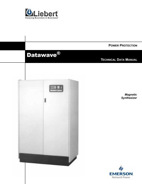
POWER PROTECTION<br />
<strong>Datawave</strong> ®<br />
TECHNICAL DATA MANUAL<br />
Magnetic<br />
Synthesizer
TABLE OF CONTENTS<br />
POWER CONDITIONING, DISTRIBUTION, CONTROL AND MONITORING FOR ANY COMPUTER SITE. . . . . . . . . . 1<br />
DEPENDABLE POWER FOR COMPUTER-DEPENDENT OPERATIONS . . . . . . . . . . . . . . . . . . . . . . . . . . . . . . . . 2<br />
ADVANTAGES THAT ADD UP TO COMPUTER-GRADE POWER YEAR AFTER YEAR . . . . . . . . . . . . . . . . . . . . . 3<br />
OPERATIONAL DESCRIPTION . . . . . . . . . . . . . . . . . . . . . . . . . . . . . . . . . . . . . . . . . . . . . . . . . . . . . . . . . . . 4<br />
APPLICATIONS GUIDELINES . . . . . . . . . . . . . . . . . . . . . . . . . . . . . . . . . . . . . . . . . . . . . . . . . . . . . . . . . . . . 5<br />
Paralleling Units . . . . . . . . . . . . . . . . . . . . . . . . . . . . . . . . . . . . . . . . . . . . . . . . . . . . . . . . . . . . . . . . . . . . 7<br />
Beyond <strong>Power</strong> Conditioning: Harmonic Isolation . . . . . . . . . . . . . . . . . . . . . . . . . . . . . . . . . . . . . . . . . . 7<br />
STANDARD FEATURES FOR ALL SYSTEMS . . . . . . . . . . . . . . . . . . . . . . . . . . . . . . . . . . . . . . . . . . . . . . . . . 8<br />
OPTIONAL FEATURES FOR ALL SYSTEMS . . . . . . . . . . . . . . . . . . . . . . . . . . . . . . . . . . . . . . . . . . . . . . . . . . 9<br />
SITE MONITORING . . . . . . . . . . . . . . . . . . . . . . . . . . . . . . . . . . . . . . . . . . . . . . . . . . . . . . . . . . . . . . . . . . 11<br />
<strong>Power</strong> Monitor Panel. . . . . . . . . . . . . . . . . . . . . . . . . . . . . . . . . . . . . . . . . . . . . . . . . . . . . . . . . . . . . . . . 11<br />
Basic Temperature Monitoring Panel . . . . . . . . . . . . . . . . . . . . . . . . . . . . . . . . . . . . . . . . . . . . . . . . . . 11<br />
SiteScan . . . . . . . . . . . . . . . . . . . . . . . . . . . . . . . . . . . . . . . . . . . . . . . . . . . . . . . . . . . . . . . . . . . . . . . . . . 12<br />
AVAILABILITY . . . . . . . . . . . . . . . . . . . . . . . . . . . . . . . . . . . . . . . . . . . . . . . . . . . . . . . . . . . . . . . . . . . . . 12<br />
SYSTEM SIZING . . . . . . . . . . . . . . . . . . . . . . . . . . . . . . . . . . . . . . . . . . . . . . . . . . . . . . . . . . . . . . . . . . . . 13<br />
PHYSICAL AND ELECTRICAL DATA . . . . . . . . . . . . . . . . . . . . . . . . . . . . . . . . . . . . . . . . . . . . . . . . . . . . . . 14<br />
Operational Characteristics . . . . . . . . . . . . . . . . . . . . . . . . . . . . . . . . . . . . . . . . . . . . . . . . . . . . . . . . . . 14<br />
Electrical Characteristics . . . . . . . . . . . . . . . . . . . . . . . . . . . . . . . . . . . . . . . . . . . . . . . . . . . . . . . . . . . . 15<br />
Heat Output. . . . . . . . . . . . . . . . . . . . . . . . . . . . . . . . . . . . . . . . . . . . . . . . . . . . . . . . . . . . . . . . . . . . . . . 16<br />
Physical and Mechanical Characteristics . . . . . . . . . . . . . . . . . . . . . . . . . . . . . . . . . . . . . . . . . . . . . . . 17<br />
Service Access and Clearance Requirements. . . . . . . . . . . . . . . . . . . . . . . . . . . . . . . . . . . . . . . . . . . . . 18<br />
i
POWER CONDITIONING, DISTRIBUTION, CONTROL AND MONITORING FOR ANY<br />
COMPUTER SITE<br />
15-30 kVA<br />
50-75 kVA<br />
100-125 kVA<br />
150-200 kVA<br />
1
DEPENDABLE POWER FOR COMPUTER-DEPENDENT OPERATIONS<br />
The Liebert <strong>Datawave</strong><br />
magnetic synthesizer<br />
provides cost effective<br />
power conditioning and<br />
protection for mainframes,<br />
minicomputers,<br />
and other electronic<br />
equipment requiring stable,<br />
noise-free power.<br />
The patented <strong>Datawave</strong><br />
magnetic synthesis process<br />
is the most dependable<br />
power conditioning<br />
technology available.<br />
Rugged components,<br />
including key circuit elements<br />
specially manufactured<br />
by Liebert, assure<br />
an extremely long service<br />
life.<br />
The <strong>Datawave</strong> power<br />
conditioner has the<br />
grounding and conditioning<br />
features demanded<br />
by today’s computer systems.<br />
Computers, as well as a<br />
variety of electronic<br />
equipment in business<br />
use today, require clean<br />
stable power.<br />
Typical electrical supply<br />
specifications are:<br />
•Voltage: ± 5%<br />
•Frequency: ±0.5 Hz<br />
•Sags/Swells: ± 10% of<br />
nominal voltage<br />
•Transients: Less than<br />
50 volts in magnitude<br />
(impulses from 0.5 to<br />
800 microseconds).<br />
Weather extremes,<br />
storms, accidental faults,<br />
momentary overloads,<br />
and even normal operation<br />
of electrical equipment<br />
can disturb power<br />
supplied by the utilities.<br />
Resulting sags, swells,<br />
transients and noise,<br />
while sometimes not<br />
noticeable in lighting and<br />
other noncritical electricity<br />
uses, can cause out-ofspec<br />
conditions, interruption<br />
of operations, and<br />
loss of data.<br />
The chart below illustrates<br />
types of disturbances<br />
and their<br />
potential effect on operations.<br />
<strong>Power</strong><br />
Conditions Definitions Causes<br />
Possible<br />
Computer Symptoms<br />
Common mode<br />
disturbances<br />
Normal mode<br />
noise<br />
Normal mode<br />
impulses &<br />
ringing<br />
transients<br />
Impulses and EMI/RFI noise with<br />
respect to ground superimposed on<br />
the power conductors.<br />
Amplitude—Millivolts to several volts<br />
for noise; hundreds of volts for<br />
impulses<br />
Low level signals superimposed on<br />
the power sinewave.<br />
Amplitude—0.5 V to 25 V<br />
Typically a narrow, fast-rise voltage<br />
variation. Can be followed by a<br />
damped oscillation decaying to<br />
nominal in less than one cycle.<br />
Amplitude—50 V to 6 kV<br />
Duration—0.5 µsec to 2000 µsec<br />
Radio transmission; Normal<br />
computer operation; Arcing contacts;<br />
Lightning; Poor grounding and<br />
shielding.<br />
Normal computer operation;<br />
Switching power supplies; <strong>Power</strong><br />
line modulation equipment (i.e.,<br />
Simplex clocks); Motor speed<br />
controllers.<br />
Switching loads on or off; Normal<br />
computer operation; Utility switching;<br />
Lightning.<br />
Incorrect data transfer from<br />
CPU to disk or tape;<br />
Terminal or printer errors;<br />
Input/output hardware<br />
damage; <strong>Power</strong> supply<br />
damage.<br />
Processing errors; Incorrect<br />
data transfer from CPU to<br />
memory; Printer or terminal<br />
errors.<br />
Incorrect data on disks or<br />
tapes; Processing errors;<br />
Printer or terminal errors;<br />
Hardware damage.<br />
Sags<br />
A low-voltage condition on one or<br />
more phases.<br />
RMS voltages below 80-85% of<br />
nominal.<br />
Duration—Greater than 1 cycle<br />
Ground faults; Starting large loads;<br />
Inadequate power system capacity;<br />
Utility switching; Utility equipment<br />
failure; Lightning.<br />
Computer system crashes;<br />
Hardware damage.<br />
Swells<br />
A high-voltage condition on one or<br />
more phases.<br />
Voltages above 110% of nominal.<br />
Duration—Greater than 1 cycle<br />
Rapid load reduction; Utility<br />
switching.<br />
Hardware damage.<br />
Waveform<br />
distortion<br />
A deviation from a true voltage<br />
sinewave.<br />
Motor speed controllers; Computer<br />
operation; Other nonlinear loads.<br />
Communication errors;<br />
Hardware damage.<br />
Single-phase<br />
outage<br />
Loss of a phase on a polyphase<br />
system.<br />
Fuse failure; Ground faults;<br />
Equipment failure; Accidents; Utility<br />
equipment failure; Lightning; Acts of<br />
nature.<br />
System crashes; Hardware<br />
damage.<br />
Outage<br />
A zero-volt condition lasting longer<br />
than a half-cycle.*<br />
Ground faults; Equipment failure;<br />
Utility equipment failure; Lightning;<br />
Acts of nature.<br />
System crashes; Hardware<br />
damage.<br />
* This is the definition of “outage” as seen by most computers. Utility companies usually define outage as a zero-volt condition lasting longer<br />
than five minutes.<br />
2
ADVANTAGES THAT ADD UP TO COMPUTER-GRADE POWER YEAR AFTER YEAR<br />
Several varieties of<br />
technologies have been<br />
applied to correct these<br />
disturbances—with<br />
varying degrees of<br />
success. Motor generator<br />
sets and line voltage<br />
regulators provide<br />
protection from some<br />
variations, but can have<br />
their own ability to<br />
supply computer grade<br />
power hampered by some<br />
electrical problems.<br />
<strong>Datawave</strong> offers<br />
protection from a wider<br />
range of power problems,<br />
maintaining voltage<br />
within specification and<br />
isolating equipment from<br />
potentially damaging<br />
variations and<br />
transients.<br />
Engineered for<br />
Inherent<br />
Dependability<br />
<strong>Datawave</strong>’s rugged simplicity<br />
ensures years of<br />
reliable operation, providing<br />
clean, stable<br />
power for decades.<br />
Equally important, the<br />
<strong>Datawave</strong> magnetic synthesizer<br />
regulates power<br />
without delicate electronic<br />
controls, highpower<br />
semiconductors,<br />
maintenance dependent<br />
mechanical drives or<br />
rotating parts.<br />
Designed for<br />
Efficiency<br />
<strong>Datawave</strong>’s efficiency of<br />
93%, along with nearly<br />
unity power factor, lowers<br />
utility costs.<br />
Limitless Future<br />
Capacity<br />
<strong>Datawave</strong> CA models,<br />
from 30 kVA up, can be<br />
paralleled to increase<br />
capacity by simply wiring<br />
them together.<br />
Load sharing is automatic.<br />
Each <strong>Datawave</strong><br />
supplies its rated amount<br />
of power.<br />
Built to Handle<br />
Computer Current<br />
Requirements<br />
Because of <strong>Datawave</strong>’s<br />
low output impedance,<br />
nonlinear current<br />
demands of modern computers<br />
are supplied with<br />
ease. Short-term currents<br />
up to 200% of the<br />
unit’s capacity can be<br />
delivered.<br />
Transient Protection<br />
The rugged <strong>Datawave</strong><br />
design withstands high<br />
energy transients without<br />
passing them along<br />
to computer equipment.<br />
The <strong>Datawave</strong> easily<br />
meets ANSI C62.41 and<br />
C62.45.<br />
Precise Voltage<br />
Regulation<br />
Sags and swells to ±40%<br />
are minimized to well<br />
within computer requirements.<br />
Input Phase Loss and<br />
Unbalance Protection<br />
Shorting, opening, or<br />
unbalance of an input<br />
phase, which typically<br />
causes motors to overheat<br />
or drop off-line, has minimal<br />
effect on <strong>Datawave</strong><br />
operation. The waveform<br />
synthesis network continues<br />
to supply 3-phase<br />
computer grade power.<br />
Balancing Unbalanced<br />
Loads<br />
Even 100% unbalanced<br />
loading of the <strong>Datawave</strong><br />
does not cause a significant<br />
change in output<br />
voltage. Variations in output<br />
are held to + 5%, -2%.<br />
Load Generated Noise<br />
Filtering<br />
Output impedance of the<br />
<strong>Datawave</strong> decreases with<br />
frequency, allowing the<br />
attenuation of load-generating<br />
noise, and<br />
impulses which could<br />
otherwise affect other<br />
devices.<br />
Input Current<br />
Distortion<br />
The <strong>Datawave</strong> absorbs<br />
harmonic currents generated<br />
by non-linear loads.<br />
The input current distortion<br />
is less than 8% THD,<br />
independent of load current<br />
distortion.<br />
Built-In Distribution<br />
Depending on application<br />
requirements, <strong>Datawave</strong><br />
can be supplied with a<br />
custom distribution system,<br />
featuring easilychangeable<br />
flexible,<br />
shielded, liquid-tight distribution<br />
cables, individually<br />
protected panelboards<br />
and separate<br />
branch circuit breakers.<br />
Sag of 40% -5%<br />
<strong>Datawave</strong> M/G Set LVR<br />
Frequency<br />
out of spec at 20%<br />
Swell of 40% +5% Out of spec<br />
Output Harmonic<br />
Distortion<br />
Less than 4%,<br />
total<br />
Less than 4%,<br />
total<br />
Voltage<br />
out of spec<br />
Voltage<br />
out of spec<br />
Typically 1% additive<br />
to input distortion<br />
Overload 150% for 20 min. 150% for 1 min. 200% for 1 min.<br />
<strong>Power</strong><br />
Efficiency<br />
Input <strong>Power</strong><br />
Factor<br />
Paralleling<br />
Capability<br />
Full load, 93%<br />
3/4 load, 91.5%<br />
1/2 load, 89%<br />
Approaches<br />
unity<br />
Unlimited<br />
Full load, 87%<br />
3/4 load, 88%<br />
1/2 load, 85%<br />
0.7 to 0.8<br />
lagging<br />
Complicated<br />
or not possible<br />
Full load, 96%<br />
3/4 load, 96%<br />
1/2 load, 96%<br />
Reflects load<br />
power factor<br />
Not possible<br />
3
OPERATIONAL DESCRIPTION<br />
The <strong>Datawave</strong> magnetic synthesizer is an electromagnetic, 3-phase AC power regenerator. Output waveforms<br />
are generated by combining pulses from saturating transformers.<br />
Three areas of regeneration enable<br />
<strong>Datawave</strong> to eliminate virtually all<br />
power line disturbances, including<br />
momentary interruptions from<br />
static switching:<br />
(1) Energy input transfer<br />
(2) Waveform building<br />
(3) Energy storage/output<br />
Energy<br />
input<br />
transfer<br />
Waveform<br />
building<br />
Energy<br />
storage/<br />
output<br />
Energy Input Transfer<br />
Input power is supplied<br />
through nonlinear chokes<br />
specially designed to provide<br />
current to the transformers<br />
independent of<br />
widely varying input<br />
voltage levels and waveform.<br />
This energy transfer<br />
technique virtually<br />
eliminates line noise and<br />
the effects of sags and<br />
swells. This current powers<br />
the waveform building<br />
circuits.<br />
Waveform<br />
Building<br />
Six interconnected saturating<br />
transformers construct<br />
the waveforms,<br />
with each transformer<br />
producing a distinct voltage<br />
pulse. Transformer<br />
geometry and construction<br />
determine the amplitude<br />
and duration of the<br />
pulses, and interconnecting<br />
circuitry combines<br />
these pulses into waveforms.<br />
Energy Storage/<br />
Output<br />
As integral elements of<br />
the interconnecting circuitry<br />
capacitors also<br />
help control the saturating<br />
sequence. Energy is<br />
dynamically stored as<br />
current in the saturated<br />
transformers, and as<br />
voltage in the capacitors.<br />
This constantly alternating<br />
energy ensures hard<br />
saturation of the transformers,<br />
precise pulse<br />
regulation and a clean,<br />
stable waveform with<br />
less than 4 percent total<br />
harmonic distortion.<br />
Three-phase power is<br />
supplied to the load<br />
through a zig-zag transformer.<br />
This configuration<br />
maintains 120°<br />
phase separation, establishes<br />
the output-circuit<br />
neutral, and assists<br />
line-to-neutral voltage<br />
regulation. The output-circuit,<br />
including the<br />
neutral, is totally isolated<br />
from input power.<br />
This unique design<br />
results in:<br />
•Reliable operation and<br />
long life<br />
•Accurate voltage regulation<br />
•Clean waveform, independent<br />
of input<br />
•High subcycle surge<br />
and safe steady-state<br />
overload protection to<br />
300 percent of nominal<br />
•Line-side and load-side<br />
noise suppression<br />
About Saturation:<br />
Inductors normally act as<br />
high-impedance circuits,<br />
supporting voltage. However,<br />
as the inductor core<br />
becomes saturated, current<br />
increases and voltage<br />
decreases. At saturation,<br />
regardless of polarity the<br />
inductor resembles a<br />
short-circuit.<br />
Current is high, and the<br />
voltage is near zero. If<br />
voltage across this saturated<br />
core is reversed, it<br />
again acts as an open circuit<br />
until saturated in<br />
the reversed direction,<br />
when it again becomes a<br />
short-circuit.<br />
About Synthesis:<br />
At any moment during<br />
operation, five of the six<br />
transformer cores are<br />
saturated, acting as<br />
short-circuits. The sixth<br />
is then saturated, and<br />
the voltage across it collapses.<br />
The sixth then<br />
reverses the voltage<br />
across the next core in<br />
the configuration, producing<br />
an unsaturated<br />
condition. As this core<br />
saturates, it reverses the<br />
voltage across still<br />
another core. This<br />
sequential switching of<br />
transformer cores produces<br />
a series of precisely<br />
defined voltage pulses<br />
used as output waveform<br />
building blocks.<br />
Transformer windings<br />
are primary-over-secondary,<br />
isolated with electrostatic<br />
shields for<br />
rejection of common-mode<br />
noise. An<br />
advantage of this configuration<br />
is that any broken<br />
circuit connection<br />
will not cause voltage<br />
supplied to the load to<br />
exceed specification.<br />
4
APPLICATIONS GUIDELINES<br />
A <strong>Datawave</strong> power conditioning system is<br />
available for almost any application.<br />
Model SC <strong>Datawave</strong><br />
Magnetic Synthesizer<br />
A Complete System in a Single Package:<br />
•Full Conditioning<br />
•Monitoring and Alarm Capabilities<br />
•Integral Branch Circuit Distribution<br />
•Flexible Distribution Cables<br />
Model CA <strong>Datawave</strong><br />
Magnetic Synthesizer<br />
The Key Building Block:<br />
•The foundation for basic <strong>Datawave</strong> power<br />
conditioning systems<br />
A <strong>Datawave</strong> system can be configured<br />
for practically any site.<br />
For Existing Distribution<br />
The Model CA can be installed to provide full<br />
conditioning capabilities in front of an existing<br />
distribution panelboard. It can also be used in<br />
old or new installations where rigid conduit is<br />
specified for distribution.<br />
The Model CA, teamed with a separate distribution<br />
module (i.e., Liebert Precision <strong>Power</strong> Center), solves<br />
the distribution problem when the conditioning module<br />
is not installed within the computer room.<br />
Remote Distribution<br />
•Used where the distance between distribution<br />
and conditioning modules is 100 ft (30 m) or less.<br />
•Voltage step-down (if required) is performed by<br />
the conditioning module.<br />
•Feeder between modules carries conditioned<br />
power at the utilization voltage level (typically<br />
120/208 volts 3-phase).<br />
•Distribution module performs distribution monitoring<br />
and control functions at point-of-use.<br />
Conditioning<br />
and<br />
Step-down<br />
Distribution<br />
5
Remote Step-Down/Distribution<br />
•Used where feeder distance between modules is<br />
between 100 and 300 feet (30 and 92 meters). If<br />
feeder distance between modules exceeds 300 feet<br />
(92 meters), consult factory.<br />
•Decreases power loss and allows use of smaller<br />
conductors and conduits between modules.<br />
•Voltage is not stepped down in the conditioning<br />
module.<br />
•Feeder between modules carries conditioned power<br />
at primary voltage level.<br />
•Distribution module, besides providing<br />
distribution, monitoring, and control functions, also<br />
performs voltage step-down and common mode<br />
noise isolation at point-of-use.<br />
Conditioning<br />
Stepdown and<br />
Distribution<br />
For Multiple Distribution<br />
The Remote Distribution System or the Remote<br />
Step-Down System can be arranged so that the<br />
Model CA <strong>Datawave</strong> feeds two or more distribution<br />
modules. Multiple-distribution systems allow shorter<br />
distribution cable runs in a large computer room and<br />
separate computer facilities to be supplied from the<br />
same conditioning system, while retaining individual<br />
distribution, control, and monitoring.<br />
For Multiple-Utility-Feed Systems<br />
Where the probability that both utility feeds would<br />
fail simultaneously is very remote, the power reliability<br />
obtained by feeding the <strong>Datawave</strong> installations<br />
from more than one utility feed can approach<br />
that obtained from a UPS system.<br />
Multiple input systems use a static transfer switch to<br />
select the input feeder for connection to the power<br />
conditioning system.<br />
Utility<br />
Feed #1<br />
Static Switch<br />
Utility<br />
Feed #2<br />
For General Distribution Systems<br />
The Model SC <strong>Datawave</strong> can be used in new office<br />
buildings to supply “noisefree” power circuits generally<br />
distributed throughout the building for desktop<br />
computers and word processors. The unbalancedload-handling<br />
capability of the <strong>Datawave</strong> magnetic<br />
synthesizer technology makes it ideal for conditioning<br />
such a distribution system, since the loads are<br />
predominantly single-phase, and cannot be closely<br />
controlled for balance. The <strong>Datawave</strong> system also<br />
provides step-down to eliminate the need for a<br />
step-down transformer.<br />
6
Paralleling Units<br />
Parallel <strong>Datawave</strong> units<br />
are used for redundancy or<br />
to power loads greater than<br />
200 kVA. <strong>Datawave</strong> magnetic<br />
synthesizers can be<br />
paralleled without special<br />
paralleling circuitry, with<br />
the resulting parallel system<br />
performing as a single<br />
magnetic synthesizer of the<br />
combined capacity.<br />
Specifications such as voltage<br />
regulation, capacity,<br />
efficiency, and harmonic<br />
distortion are not affected<br />
by paralleling.<br />
Output switchgear<br />
To load<br />
distribution<br />
Beyond <strong>Power</strong> Conditioning: Harmonic Isolation<br />
Today, as more and more<br />
users of electronic equipment<br />
become concerned<br />
about harmonics, the<br />
<strong>Datawave</strong> Magnetic Synthesizer<br />
is being increasingly<br />
applied as a<br />
harmonic isolator.<br />
Because of its basic operation,<br />
the <strong>Datawave</strong><br />
Magnetic Synthesizer<br />
isolates its output from<br />
its input. This capability<br />
allows the <strong>Datawave</strong> system<br />
to provide harmonic<br />
isolation as well as power<br />
conditioning. The output<br />
voltage is regenerated,<br />
free of any input voltage<br />
distortion, notching or<br />
transients.<br />
Further, the <strong>Datawave</strong><br />
system is designed to be<br />
compatible with nonlinear<br />
loads without derating,<br />
including singlephase,<br />
switched-mode<br />
power supplies.<br />
The <strong>Datawave</strong> Magnetic<br />
Synthesizer isolates the<br />
power system from the<br />
harmonic current distortion<br />
caused by nonlinear<br />
loads. Its input current<br />
distortion remains less<br />
than 8% THD even with<br />
output load current distortions<br />
over 110% THD.<br />
Input voltage distortion<br />
notching and transients<br />
Output voltage distortion<br />
STANDARD FEATURES FOR ALL SYSTEMS<br />
All Liebert <strong>Datawave</strong><br />
systems incorporate a<br />
number of standard features<br />
to ensure load protection<br />
and to simplify<br />
maintenance.<br />
The <strong>Datawave</strong> magnetic<br />
synthesizer uses<br />
heavy-duty dry type<br />
transformers and high<br />
reliability capacitors to<br />
regenerate clean output<br />
power. <strong>Power</strong> to the critical<br />
load is regulated to<br />
within ±5% for input<br />
power varying from<br />
+40% to -40% of nominal.<br />
(Refer to Operational<br />
Description on page 4<br />
and Voltage<br />
Regulation on<br />
page 14.)<br />
Each magnetic component<br />
in the magnetic synthesizer<br />
is equipped with<br />
two temperature sensors<br />
in the windings.<br />
One sensor provides an<br />
alarm if any internal<br />
temperature exceeds<br />
180°C, the other shuts<br />
down the system if any<br />
internal temperature<br />
exceeds 200°C, even<br />
though full class H 220°C<br />
transformer insulation is<br />
utilized.<br />
A main input circuit<br />
breaker provides either<br />
manual control or automatic<br />
shutdown of the<br />
system in the event of an<br />
overcurrent condition.<br />
The breaker is<br />
molded-case, rated to<br />
provide coordination with<br />
output protection<br />
devices. In addition to<br />
manual and thermal-magnetic<br />
trip, the<br />
input breaker can be<br />
tripped by an electrically<br />
actuated shunt trip<br />
mechanism. As a standard<br />
feature, the shunt<br />
trip of the input circuit<br />
breaker is activated by<br />
the 200°C temperature<br />
sensors, local Emergency<br />
<strong>Power</strong> Off switch, and<br />
Manual Restart circuit.<br />
The local Emergency<br />
<strong>Power</strong> Off (EPO)<br />
switch is an illuminated<br />
push button, easily accessible<br />
for emergency shutdown<br />
use, but fully<br />
guarded to prevent accidental<br />
operation.<br />
Input circuit breaker<br />
The manual restart circuit<br />
shunt-trips the main<br />
input breaker whenever<br />
input power is lost. This<br />
isolates the system from<br />
repetitive power applications<br />
during fault-clearing<br />
operations by the<br />
utility and allows an<br />
orderly restart of the system<br />
when normal power<br />
returns.<br />
The manual restart circuit<br />
can be disabled by<br />
the manual restart<br />
switch. The auto position<br />
of the switch defeats<br />
manual restart, and<br />
allows the conditioner to<br />
automatically restart<br />
when power returns.<br />
Auto restart is useful for<br />
unattended remote sites<br />
where the load can automatically<br />
restart, and in<br />
those applications when<br />
the manual restart function<br />
is provided elsewhere<br />
in the system.<br />
The low-voltage shunt<br />
trip circuit also allows<br />
system shutdown by<br />
external relays, Remote<br />
Emergency <strong>Power</strong> Off<br />
(REPO) switches, or<br />
other remote devices.<br />
A double-pole, doublethrow<br />
(dpdt) building<br />
interface relay is powered<br />
by a 24 volt DC supply<br />
from the output of the<br />
magnetic synthesizer<br />
Energized whenever the<br />
<strong>Datawave</strong> system is on,<br />
the relay drops out if the<br />
output voltage disappears<br />
for any reason. The<br />
relay can be used for<br />
remote alarming of system<br />
shutdown, or shutdown<br />
interface with<br />
additional loads such as<br />
environmental control<br />
units.<br />
<strong>Datawave</strong> system components<br />
are housed in a<br />
welded steel frame<br />
with removable cabinet<br />
panels to provide maximum<br />
accessibility to the<br />
interior For safety and<br />
security, any panels<br />
which provide access to<br />
high voltage areas<br />
require a tool for<br />
removal.<br />
Cabinet colors are available<br />
to match or accent<br />
the computer equipment<br />
or room decor.<br />
Temperature sensors<br />
8
OPTIONAL FEATURES FOR ALL SYSTEMS<br />
Individually<br />
Protected Panelboards<br />
One 42-pole panelboard<br />
is provided on 15-30 kVA<br />
Model SC units; two (for<br />
a total of 84 poles) are<br />
provided on 50-75 kVA<br />
SC units; and four 30<br />
pole panelboards for a<br />
total of 120 poles are<br />
provided for 100-200 kVA<br />
SC units. Each<br />
panelboard is protected<br />
by a main circuit breaker<br />
to prevent overload and<br />
allow manual shutdown<br />
of the entire panelboard.<br />
Each panelboard is<br />
enclosed for safety, and<br />
has individual isolated<br />
neutral and safety<br />
ground busbars.<br />
Output circuits are<br />
protected by single-, two-,<br />
or three-pole thermalmagnetic<br />
molded-case<br />
branch circuit breakers<br />
sized specifically for the<br />
load to be served.<br />
(Standard panelboards<br />
use plug-in breakers.)<br />
Optional Panelboard<br />
Types<br />
Branch circuit<br />
panelboards which<br />
accept bolt-in type circuit<br />
breakers are optional for<br />
the <strong>Datawave</strong> system, as<br />
are panelboards for<br />
plug-in or bolt-in<br />
breakers manufactured<br />
by Square-D Corp.<br />
Flexible Output Cables<br />
& Terminations<br />
A flexible output cable<br />
system is available for SC<br />
units. Cable conductors<br />
are protected by a jacketed,<br />
liquid-tight, flexible<br />
steel conduit with a copper<br />
shielding conductor.<br />
Each output cable is fabricated<br />
to any specified<br />
length and type of termination<br />
to match the<br />
equipment to which it is<br />
to be connected<br />
Add-on cables for field<br />
installation can also be<br />
fabricated. Terminations<br />
include:<br />
•Receptacles to match<br />
equipment plugs.<br />
•Conduit termination<br />
fittings with conductor<br />
“pigtails” for hard wire<br />
connection.<br />
Subfeed Output Circuit<br />
Breaker<br />
A subfeed output circuit<br />
breaker, powered ahead<br />
of the output panelboards,<br />
is available on<br />
the Self-Contained <strong>Datawave</strong><br />
units to feed a<br />
remote distribution unit,<br />
panelboards, or other<br />
loads.<br />
A single subfeed breaker<br />
(225-amp max) is available<br />
on Model SC 50 or<br />
75 kVA systems. Either<br />
one (400-amp max) or<br />
two (225-amp each max)<br />
subfeed output breakers<br />
are available on Model<br />
SC 100-200 kVA systems.<br />
Main Output Circuit<br />
Breaker<br />
A molded case, thermal<br />
magnetic circuit breaker<br />
sized for 125% of the<br />
<strong>Datawave</strong>’s output full<br />
load amps is provided on<br />
all standard CA units.<br />
The main output circuit<br />
breaker provides a main<br />
disconnect and overcurrent<br />
protection for the<br />
<strong>Datawave</strong> output power<br />
feeder.<br />
High-Voltage Junction<br />
Box With Flexible<br />
Input Cable<br />
The high-voltage junction<br />
box can be installed under<br />
a raised floor system. The<br />
junction box contains terminals<br />
for connecting the<br />
incoming power line and<br />
ground conductors. A 10ft<br />
(3m) flexible cable is furnished<br />
for connection<br />
between the junction box<br />
and the <strong>Datawave</strong> main<br />
input circuit breaker.<br />
Low-Voltage Junction<br />
Box with Flexible<br />
Input Cable<br />
The low-voltage junction<br />
box can be installed<br />
under a raised floor. It<br />
contains terminals for<br />
connection of all building<br />
interface alarms or controls,<br />
and all Remote<br />
Emergency <strong>Power</strong> Off<br />
switches. A 10ft (3m)<br />
flexible control cable for<br />
the system is furnished<br />
for connection between<br />
the junction box and the<br />
<strong>Datawave</strong> system.<br />
9
Reserve Input Junction<br />
Box with Flexible<br />
Input Cable<br />
The reserve input highvoltage<br />
junction box can<br />
be installed under a<br />
raised floor system. The<br />
junction box contains terminals<br />
for connecting the<br />
reserve input power line,<br />
neutral, and ground conductors.<br />
A 10-foot<br />
(3-meter) flexible cable is<br />
furnished for connection<br />
between the junction box<br />
and the <strong>Datawave</strong><br />
reserve input circuit<br />
breaker.<br />
Remote Emergency<br />
<strong>Power</strong> Off (REPO)<br />
Switch<br />
Secondary Class<br />
Surge Arrester<br />
A secondary class surge<br />
arrester is wired to all<br />
three phases of the input<br />
power to shunt otherwise<br />
damaging voltage<br />
surges to the building<br />
ground.<br />
The arrester is rated for<br />
a maximum FOW sparkover<br />
of 3200 volts with<br />
maximum discharge voltage<br />
of 2.2 kV at 1500<br />
amperes, assuming a<br />
standard 8 x 20 microsecond<br />
waveform.<br />
The sure arrester provides<br />
protection for the<br />
<strong>Datawave</strong> against those<br />
very high voltage surges<br />
which can cause insulation<br />
or wiring failures.<br />
Bypass Transformer<br />
The bypass transformer<br />
is a 3-phase isolation<br />
transformer, furnished in<br />
a NEMA 1 (general purpose)<br />
enclosure. The<br />
bypass transformer is<br />
used with the bypass<br />
switch to provide stepdown<br />
and/or isolation for<br />
the bypass leg of the<br />
<strong>Datawave</strong> system.<br />
An optional decorative<br />
cabinet may be provided<br />
when desired. The cabinet<br />
color may be selected<br />
to match or accent the<br />
room decor.<br />
Floor Pedestals<br />
In rooms without a<br />
raised floor, the floor pedestals<br />
provide space for<br />
the bottom entrance of<br />
cables (and cooling air).<br />
The height of the floor<br />
pedestals is customerspecified.<br />
Standard floor pedestal<br />
height range: adjustable<br />
from 8.6 to 13.3 in.<br />
(218 to 336mm).<br />
Other available ranges<br />
are: 6 to 8.5 in. (152 to<br />
216mm), and 13.5 to<br />
18 in. (343 to 457mm).<br />
Bypass Switch<br />
Transient Suppression<br />
Plate<br />
The transient suppression<br />
plate is a one square<br />
meter metal plate<br />
mounted to (and bonded<br />
to) the high-voltage junction<br />
box. It reduces the<br />
effects of transients on<br />
the ground system by<br />
providing a capacitive<br />
coupling to building<br />
steel.<br />
Phase Rotation Meter<br />
The phase rotation meter<br />
is a handheld instrument<br />
with clip-on leads for connecting<br />
to the circuit<br />
under test. Upon meter<br />
connection and circuit<br />
energization, the meter<br />
shows whether the circuit<br />
phase rotation is in<br />
“ABC” or “BAC”<br />
sequence.<br />
The phase rotation meter<br />
can be used to verify the<br />
rotation sequence of any<br />
three-phase circuit up to<br />
600 volts.<br />
Pressing the REPO push<br />
button activates the<br />
shunt trip mechanism of<br />
the main input circuit<br />
breaker, shutting down<br />
the system.<br />
The illuminated and fully<br />
guarded REPO button is<br />
mounted in a wall box.<br />
The assembly includes<br />
50 feet (15.2 meters) of<br />
3-conductor cable for wiring<br />
to the building interface<br />
system. Additional<br />
lengths of cable are available.<br />
The bypass switch facilitates<br />
system maintenance<br />
by allowing the<br />
magnetic synthesizer of<br />
the <strong>Datawave</strong> system to<br />
be taken out of the circuit,<br />
or bypassed, with<br />
continued system operation.<br />
10
SITE MONITORING<br />
Monitoring systems for<br />
Liebert power conditioners<br />
range from temperature<br />
sensing to multipleparameter<br />
monitoring<br />
with remote display and<br />
printout.<br />
All units are equipped<br />
with a guarded and<br />
illuminated Local<br />
Emergency <strong>Power</strong> Off<br />
switch; provisions for<br />
connecting Remote<br />
Emergency <strong>Power</strong> Off<br />
switch; selectable auto or<br />
manual restart feature,<br />
to allow an orderly<br />
system restart after a<br />
power failure; a<br />
summary alarm contact;<br />
and a building interface<br />
relay.<br />
<strong>Power</strong> Monitor<br />
Panel<br />
True RMS techniques<br />
are used to provide<br />
accurate measurements<br />
of <strong>Datawave</strong><br />
operation, while the<br />
high visibility Liquid<br />
Crystal Display provides<br />
clear reporting.<br />
The, microprocessorbased<br />
power monitoring<br />
system continuously<br />
monitors and sequentially<br />
displays the following<br />
parameters:<br />
•Input voltages, line-toline<br />
for each phase<br />
•Output voltages, lineto-line<br />
and line-toneutral<br />
for each phase<br />
•Output currents for<br />
each phase, including<br />
neutral and ground<br />
currents<br />
•Output voltage THD<br />
for each phase<br />
•Output current THD<br />
for each phase<br />
•K-factor and crest factor<br />
•Output power including<br />
kVA, kW, kW-<br />
Hours, power factor,<br />
percent load and output<br />
frequency.<br />
The monitor panel also<br />
provides warning of outof-spec<br />
conditions<br />
through audible alarm<br />
and displayed alarm<br />
messages. All alarmed<br />
conditions are retained<br />
in a nonvolatile memory<br />
until reset. Alarm<br />
thresholds are adjustable<br />
to meet individual<br />
site needs.<br />
Alarmed conditions<br />
include:<br />
•Output overvoltage<br />
•Output undervoltage<br />
•Output voltage THD<br />
•Output overcurrent<br />
•Neutral overcurrent<br />
•Ground overcurrent<br />
•Transformer overtemperature<br />
•Frequency deviation<br />
•Phase sequence error<br />
•Phase loss<br />
•Five customer-specified<br />
alarm conditions.<br />
For additional application<br />
flexibility, the following<br />
alarms can be<br />
configured to shut down<br />
the system:<br />
•Output over-/undervoltage<br />
•Phase sequence error/<br />
phase loss<br />
•Ground overcurrent<br />
Through a two-conductor<br />
communications<br />
cable, the system can<br />
communicate alarms<br />
and monitored conditions<br />
to a Liebert Site-<br />
Scan central monitoring<br />
system. An isolated RS-<br />
232 ASCII communication<br />
port is provided for<br />
communication to other<br />
monitoring systems.<br />
Basic Temperature Monitoring Panel<br />
The Transformer Overtemperature alarm indicator is a part of the 180°C transformer temperature sensing<br />
circuit. This configuration is optional on all units.<br />
11
SiteScan<br />
SiteScan is an online<br />
center for monitoring and<br />
controlling all support<br />
systems in a large data<br />
processing installation.<br />
SiteScan provides early<br />
warning alarms and total<br />
site management data. A<br />
software-based system<br />
using a microcomputer<br />
as the central processing<br />
center, SiteScan is<br />
programmable, menudriven,<br />
and upgradeable.<br />
Four primary site management<br />
programs are<br />
built into SiteScan:<br />
Alarm functions provide<br />
instant warning of potential<br />
problems. A seven<br />
level selection of options<br />
for response to each<br />
alarm offers total flexibility<br />
in designing a custom-tailored<br />
alarm<br />
system.<br />
Control functions allow<br />
critical setpoints and<br />
sensitivities to be<br />
adjusted by remote control<br />
for dynamic, singlepoint<br />
site management.<br />
Password access preserves<br />
site security.<br />
Status functions provide<br />
complete information on<br />
all computer support systems,<br />
including real-time<br />
status of all monitored<br />
parameters and any<br />
alarm conditions.<br />
History functions offer<br />
database management<br />
capabilities. These<br />
functions track, store and<br />
graphically display<br />
crucial data and trends<br />
for site management<br />
activities such as<br />
capacity analysis, growth<br />
predictions, and energy<br />
management.<br />
SiteScan makes full use<br />
of all features of its<br />
computer-based central<br />
processor, including<br />
RS-232 communications<br />
and other output ports<br />
and unlimited expansion<br />
via multiplexers.<br />
For critical data<br />
processing facilities,<br />
the SiteScan system<br />
offers total site<br />
management capability<br />
in a virtually<br />
obsolescence-proof<br />
configuration.<br />
AVAILABILITY<br />
Individually protected<br />
panelboards<br />
Flexible Output Cables<br />
and Terminations<br />
Optional Panelboard<br />
Types<br />
Subfeed Output<br />
Circuit Breaker<br />
Main Output<br />
Circuit Breaker<br />
High-Voltage Junction Box<br />
With Flexible Input Cable<br />
Low-Voltage Junction Box<br />
With Flexible Input Cable<br />
Reserve Input Junction Box<br />
With Flexible Input Cable<br />
Secondary Class Surge<br />
Arrester<br />
Remote Emergency <strong>Power</strong><br />
Off (REPO) Switch<br />
Model SC<br />
Model CA<br />
15-30 kVA 50-75 kVA 100-200 kVA 15-30 kVA 50-75 kVA 100-200 kVA<br />
Standard<br />
(panelboard)<br />
42 poles<br />
Standard<br />
(2 panelboards)<br />
84 poles<br />
Standard<br />
(4 panelboards)<br />
120 poles<br />
Not<br />
applicable<br />
Optional Optional Optional Not<br />
applicable<br />
Optional Optional Optional Not<br />
applicable<br />
Not<br />
available<br />
Optional Optional Not<br />
applicable<br />
Not<br />
applicable<br />
Not<br />
applicable<br />
Not<br />
applicable<br />
Not<br />
applicable<br />
Not<br />
applicable<br />
Not<br />
applicable<br />
Not<br />
applicable<br />
Not<br />
applicable<br />
Not available Not available Not available Standard Standard Standard<br />
Standard Standard Optional Optional Optional Optional<br />
Optional Optional Optional Optional Optional Optional<br />
Not<br />
applicable<br />
Not<br />
applicable<br />
Optional with<br />
Bypass Switch<br />
Not<br />
applicable<br />
Not<br />
applicable<br />
Optional with<br />
Bypass Switch<br />
Optional Optional Optional Optional Optional Optional<br />
Optional Optional Optional Optional Optional Optional<br />
Floor Pedestals Optional Optional Optional Optional Optional Optional<br />
Bypass Switch Optional Optional Optional Optional Optional Optional<br />
Bypass Transformer Optional Optional Optional Optional Optional Optional<br />
Transient Suppression<br />
Plate<br />
Optional with<br />
high-voltage<br />
junction box<br />
Optional with<br />
high-voltage<br />
junction box<br />
Optional with<br />
high-voltage<br />
junction box<br />
Optional with<br />
high-voltage<br />
junction box<br />
Optional with<br />
high-voltage<br />
junction box<br />
Optional with<br />
high-voltage<br />
junction box<br />
<strong>Power</strong> Monitor Panel Standard Standard Standard Optional Optional Optional<br />
SiteScan Optional Optional Optional Optional Optional Optional<br />
12
SYSTEM SIZING<br />
A fundamental concern is the size of the conditioning system required to<br />
meet present and future needs.<br />
Present Requirements<br />
Estimating the present system size can be done in a number of ways,<br />
depending on the source of information available. Typical sources include<br />
the computer site planning manuals, equipment nameplate data, and the<br />
existing electrical service data. Present kVA requirements can be estimated<br />
using any of the following:<br />
1. Kilowatts (kW) and <strong>Power</strong> Factor (pf)<br />
kVA<br />
=<br />
kW<br />
----<br />
pf<br />
(If pf is not given, assume an average of 0.80.)<br />
2. Ampere specifications for the electrical service feeding the data<br />
processing area.<br />
kVA<br />
=<br />
V<br />
----------------<br />
× A × 3<br />
1000<br />
(for 3-phase systems)<br />
3. BTU/hr or kcal/hr specifications.<br />
kW = ------------------<br />
( BTU) ⁄ ( hr)<br />
kW =<br />
3413<br />
kVA<br />
=<br />
kW<br />
----<br />
pf<br />
(If pf is not given, assume an average of 0.80.)<br />
4. <strong>Power</strong> profile of equipment. (When available, this is the most reliable<br />
base from which to estimate present kVA loading.)<br />
For 3-phase equipment:<br />
kVA<br />
A<br />
V × A × 3<br />
= ----------------<br />
1000<br />
kVA × 1000<br />
= ----------------<br />
V × 3<br />
For single-phase equipment:<br />
kVA<br />
A<br />
= --------<br />
V × A<br />
1000<br />
=<br />
kVA<br />
----------------<br />
× 1000<br />
V<br />
(<br />
-----------------<br />
kcal) ⁄ ( hr)<br />
860<br />
After the present kVA requirement has been determined the anticipated<br />
growth and the special characteristics of the load must be considered.<br />
Growth Requirements<br />
The <strong>Datawave</strong> should be<br />
sized anticipating growth<br />
to protect against shortterm<br />
obsolescence. With<br />
the growth rates associated<br />
with data processing<br />
centers, their power<br />
requirements double in a<br />
relatively short time.<br />
Therefore it is not unreasonable<br />
to size the conditioner<br />
for twice (or 200%<br />
of) the present estimated<br />
kVA load. Even in a minimum<br />
growth environment,<br />
the conditioner should be<br />
sized for 125% of the estimated<br />
kVA load.<br />
Special Load<br />
Characteristics<br />
Whenever special load<br />
characteristics are encountered,<br />
factory application<br />
engineers should be consulted<br />
for recommended<br />
system sizing.<br />
System Grounding<br />
Considerations<br />
The grounding of any<br />
power conditioning system<br />
is critical to its performance.<br />
When grounding<br />
for system performance,<br />
however, the first rule<br />
must always be safety.<br />
What good is a system that<br />
performs, but is not safe?<br />
The National Electrical<br />
Code provides for a safe<br />
electrical system. The<br />
ground path required by<br />
the NEC for safety should<br />
be enhanced or improved<br />
for a system performance,<br />
never defeated or eliminated.<br />
For detailed system<br />
grounding considerations,<br />
refer to the installation<br />
manual.<br />
13
PHYSICAL AND ELECTRICAL DATA<br />
Operational Characteristics<br />
Input Transients<br />
No spikes, transients, or<br />
other disturbances are<br />
evident on any of the<br />
three output phases<br />
when high-energy, ringing<br />
transients (ANSI<br />
C62.41, Category B) are<br />
impressed on the input<br />
lines.<br />
Electrical Noise<br />
Suppression<br />
Voltage Regulation<br />
Type<br />
Input voltage<br />
(% of Nominal) Load<br />
Output Voltage<br />
(% of Nominal)<br />
Normal Nominal 0% to 100% Nominal to +3%<br />
High line/Low line +40% to -40% 0% to 100% +5% to -5%<br />
Unbalanced input<br />
voltage<br />
Unbalanced<br />
load<br />
Nominal<br />
(single-phase)<br />
Nominal<br />
0% to 60% +5.8% to -4%<br />
100% on two phases<br />
0% on one phase<br />
Overload Nominal 200% -6%<br />
+5% to -2%<br />
Type<br />
Normal<br />
mode<br />
Common<br />
mode<br />
Suppression<br />
120 dB<br />
120 dB<br />
Short-Circuit<br />
Capability<br />
The sustained short-circuit<br />
current available<br />
from the <strong>Datawave</strong> magnetic<br />
synthesizer is up to<br />
+200% of full-load current<br />
(continuously, or<br />
until protection circuitry<br />
is activated).<br />
Output Voltage<br />
Harmonic Distortion<br />
(No-load to Full-load)<br />
Total Harmonic Distortion—less<br />
than 4%<br />
NOTE: Incoming line distortion<br />
is not additive to<br />
output Total Harmonic<br />
Distortion.<br />
Efficiency (Nominal Input Voltage)<br />
15-20 kVA 30 kVA 50-200 kVA<br />
Full-load 89% 91% 93%<br />
Three-quarter load 87% 89% 91.5%<br />
Half-load 83% 86% 89%<br />
Input <strong>Power</strong><br />
Factor<br />
From half-load to fullload—0.96<br />
lead to 0.96<br />
lag.<br />
NOTE: Input power factor<br />
does not depend on<br />
load.<br />
Input Current<br />
Distortion<br />
Total Harmonic Distortion—less<br />
than 8%<br />
NOTE: Input current<br />
distortion is independent<br />
of load power factor<br />
current distortion.<br />
Audible Noise<br />
15-30 kVA 55 dBA<br />
50-75 kVA 58 dBA<br />
100-200 kVA 63 dBA<br />
NOTE: Average sound<br />
level, measured at 5 feet<br />
(1.6 meters).<br />
14
Electrical Characteristics<br />
Table 1 Electrical Characteristics<br />
Main Input<br />
Output & Reserve Input<br />
Suggested Feeder<br />
Suggested Feeder<br />
Voltage kVA FLA OPD Wire Size (AWG) FLA OPD Wire Size (AWG)<br />
15 49 60 6 42 60 6<br />
20 65 80 4 56 70 4<br />
30 95 125 1 83 110 2<br />
50 155 200 000 139 175 00<br />
208V 75 233 300 350 kcmil 208 300 350 kcmil<br />
100 311 400 000 (2*) 277 350 500 kcmil<br />
125 389 500 250 kcmil (2*) 347 450 0000 (2*)<br />
150 466 600 350 kcmil (2*) 416 600 350 kcmil (2*)<br />
200 622 800 300 kcmil (3*) 555 700 500 kcmil (2*)<br />
15 42 60 6<br />
20 56 70 4<br />
30 83 100 2<br />
50 135 175 00<br />
240V 75 202 250 250 kcmil<br />
100 269 350 500 kcmil<br />
125 337 450 0000 (2*)<br />
150 404 500 250 kcmil (2*)<br />
200 539 700 500 kcmil (2*)<br />
15 27 40 8 23 30 10<br />
20 36 50 8 30 40 8<br />
30 52 70 4 46 60 6<br />
50 85 110 2 76 100 3<br />
380V 75 127 175 00 114 150 0<br />
100 170 225 0000 152 200 000<br />
125 213 300 350 kcmil 190 250 250 kcmil<br />
150 255 350 500 kcmil 228 300 350 kcmil<br />
200 340 450 0000 (2*) 304 400 000 (2*)<br />
15 25 40 8 22 30 10<br />
20 34 50 8 29 40 8<br />
30 50 70 4 43 60 6<br />
50 81 110 2 72 90 3<br />
400V 75 121 175 00 108 150 0<br />
100 162 200 000 144 200 000<br />
125 202 250 250 kcmil 180 225 0000<br />
150 243 300 350 kcmil 217 300 350 kcmil<br />
200 323 400 000 (2*) 289 400 000 (2*)<br />
15 24 30 10 21 30 10<br />
20 33 40 8 28 40 8<br />
30 48 60 6 42 60 6<br />
50 78 100 3 70 90 3<br />
415V 75 117 150 0 104 150 0<br />
100 156 200 000 139 175 00<br />
125 195 250 250 kcmil 174 225 0000<br />
150 234 300 350 kcmil 209 300 350 kcmil<br />
200 312 400 000 (2*) 278 350 500 kcmil<br />
15 21 30 10 18 25 10<br />
20 28 40 8 24 30 10<br />
30 41 50 8 36 50 8<br />
50 67 90 3 60 80 4<br />
480V 75 101 125 1 90 125 1<br />
100 135 175 00 120 150 0<br />
125 168 225 0000 150 200 000<br />
150 202 250 250 kcmil 180 225 0000<br />
200 269 350 500 kcmil 241 300 350 kcmil<br />
15 17 25 10 14 20 12<br />
20 22 30 10 19 25 10<br />
30 33 50 8 29 40 8<br />
50 54 70 4 48 60 6<br />
600V 75 81 110 2 72 90 3<br />
100 108 150 0 96 125 1<br />
125 135 175 00 120 150 0<br />
150 162 225 0000 144 200 000<br />
200 216 300 350 kcmil 192 250 250 kcmil<br />
* Number of parallel feeders<br />
Voltage and Current Ratings<br />
The <strong>Datawave</strong> magnetic synthesizer<br />
has nine kVA capacities,<br />
from 15 kVA through 200 kVA.<br />
A range of voltage capabilities is<br />
available for each size, in both<br />
50 and 60 Hz. Table 1 shows<br />
common voltages, Full Load<br />
Ampere (FLA) values, and circuit<br />
breaker (OPD) ratings.<br />
(For voltage ratings not shown,<br />
consult Factory).<br />
NOTES:<br />
1. FLA = Full Load Amps of <strong>Datawave</strong><br />
system.<br />
OPD= Overcurrent Protection Device<br />
inside <strong>Datawave</strong> unit.<br />
(2*) = Two parallel feeders per NEC<br />
300-20 and 310-4.<br />
Wire Sizes based on NEC 1996 Table<br />
310-16, using 75°C copper conductor.<br />
2. Input feeder wire size listed in Table is<br />
the minimum feeder size<br />
recommended. Larger wire size may be<br />
required because of voltage drop or<br />
supply OPD.<br />
3. Output feeder and Reserve Input feeder<br />
size listed in Table is the minimum size<br />
recommended. Larger wire size may be<br />
required because of voltage drop or<br />
harmonic neutral current (Ref. NEC<br />
Table 310-16 Notes 8 and 10). For best<br />
performance, Synthesizer should be<br />
located as close to the load as practical.<br />
4. Insulated ground conductors are<br />
recommended to be parity sized with<br />
power conductors for increased system<br />
performance. Ground conductor<br />
minimum size must be per NEC, Table<br />
250-95. Input power feeder conduit may<br />
be used as safety ground (customer<br />
option). If conduit is used, adequate<br />
electrical continuity must be maintained<br />
at conduit connection to enclosures and<br />
throughout conduit run.<br />
5. Reserve input is used in bypass mode<br />
of <strong>Datawave</strong> system (100-200 kVA).<br />
Reserve input voltage must be same as<br />
<strong>Datawave</strong> system output voltage.<br />
6. The Main Output Breaker listed in the<br />
table is typical for Model CA units only.<br />
7. Standard Breaker Interrupting Ratings<br />
as follows. Other ratings available upon<br />
request.<br />
OPD 208V 380-415V 480V 600V<br />
Up to<br />
250A<br />
65KA 15KA 35KA 22KA<br />
300-<br />
600A<br />
65KA 25KA 35KA 25KA<br />
700-<br />
800A<br />
65KA 50KA 50KA 25KA<br />
15
Heat Output<br />
The <strong>Datawave</strong> magnetic<br />
synthesizer is the most<br />
efficient of the power<br />
synthesizing technologies.<br />
As the <strong>Datawave</strong><br />
operates, some energy is<br />
lost in the form of heat.<br />
Table 2 shows the heat<br />
output of the <strong>Datawave</strong><br />
system for each model at<br />
one-half, three-quarter,<br />
and full loads (based on a<br />
unity load power factor).<br />
Table 2<br />
Heat output<br />
Size<br />
One-half<br />
load<br />
Three-quarter<br />
load<br />
Full<br />
load<br />
kVA/kW BTU/hr (kW) BTU/hr (kW) BTU/hr (kW)<br />
15 5250 (1.54) 5750 (1.68) 6350 (1.85)<br />
20 6990 (2.05) 7650 (2.24) 8450 (2.47)<br />
30 8350 (2.44) 9490 (2.78) 10125 (2.97)<br />
50 10550 (3.09) 11890 (3.48) 12850 (3.76)<br />
75 15820 (4.63) 17830 (5.23) 19270 (5.65)<br />
100 21090 (6.18) 23780 (6.97) 25700 (7.53)<br />
125 26360 (7.72) 29720 (8.71) 32100 (9.41)<br />
150 31640 (9.3) 35670 (10.5) 38500 (11.3)<br />
200 42180 (12.4) 45760 (13.9) 51400 (15.1)<br />
Environmental characteristics are:<br />
•Temperature, operating 0°C to +40°C<br />
•Temperature, storage -55°C to +85°C<br />
•Relative humidity<br />
0% to 95% (non-condensing)<br />
16
Physical and Mechanical Characteristics<br />
Weights and Dimensions<br />
The weights and dimensions of the <strong>Datawave</strong> magnetic<br />
synthesizers are shown in Table 3.<br />
(All weights and dimensions are those of an uncrated<br />
unit, less cables and floor pedestals.)<br />
Floor Loading<br />
Data for both distributed and concentrated floor loading<br />
of the <strong>Datawave</strong> magnetic synthesizer are shown<br />
in Table 4. Distributed floor loading values reflect<br />
the weight of the unit over its entire footprint area,<br />
and is expressed in lb/ft 2 or kg/m 2 . Concentrated floor<br />
loading values reflect the weight of the unit at each<br />
point of support.<br />
Table 3<br />
Weight and dimensions<br />
Table 4<br />
Floor loading<br />
Size 60 Hz 50 Hz W x D x H<br />
kVA<br />
15<br />
20<br />
30<br />
50<br />
75<br />
100<br />
125<br />
150<br />
Module A<br />
150<br />
Module B<br />
200<br />
Module A<br />
200<br />
Module B<br />
lbs<br />
(kg)<br />
1200<br />
(545)<br />
1500<br />
(680)<br />
1600<br />
(730)<br />
2400<br />
(1090)<br />
2750<br />
(1250)<br />
3900<br />
(1775)<br />
4300<br />
(1955)<br />
2650<br />
(1205)<br />
3150<br />
(1430)<br />
3000<br />
(1365)<br />
3500<br />
(1590)<br />
lbs<br />
(kg)<br />
1300<br />
(590)<br />
1600<br />
(730)<br />
1700<br />
(775)<br />
2640<br />
(1200)<br />
3025<br />
(1375)<br />
4400<br />
(2000)<br />
4900<br />
(2230)<br />
2990<br />
(1360)<br />
3500<br />
(1590)<br />
3410<br />
(1550)<br />
3940<br />
(1790)<br />
Inches<br />
(mm)<br />
36x34x64<br />
(914x863x1626)<br />
36x34x64<br />
(914x863x1626)<br />
36x34x64<br />
(914x863x1626)<br />
44x32x68<br />
(1118x813x1727)<br />
44x32x68<br />
(1118x813x1727)<br />
66x36x76<br />
(1676x914x1931)<br />
66x36x76<br />
(1676x914x1931)<br />
52x36x76<br />
(1321x914x1931)<br />
52x36x76<br />
(1321x914x1931)<br />
52x36x76<br />
(1321x914x1931)<br />
52x36x76<br />
(1321x914x1931)<br />
Size<br />
Distributed floor loading<br />
(Wt. per unit area)<br />
lb/ft 2<br />
kVA (kg/m 2 )<br />
15 141<br />
(691)<br />
20 176<br />
(862)<br />
30 188<br />
(925)<br />
50 245<br />
(1199)<br />
75 281<br />
(1375)<br />
100 236<br />
(1159)<br />
125 261<br />
(1276)<br />
150<br />
Module A<br />
150<br />
Module B<br />
200<br />
Module A<br />
200<br />
Module B<br />
Concentrated floor loading<br />
(Wt. at each support point)<br />
60 Hz 50 Hz 60 Hz 50 Hz<br />
204<br />
(998)<br />
242<br />
(1184)<br />
231<br />
(1131)<br />
269<br />
(1317)<br />
lb/ft 2<br />
(kg/m 2 )<br />
153<br />
(748)<br />
188<br />
(925)<br />
200<br />
(983)<br />
270<br />
(1320)<br />
309<br />
(1513)<br />
267<br />
(1305)<br />
297<br />
(1456)<br />
230<br />
(1126)<br />
269<br />
(1317)<br />
262<br />
(1284)<br />
303<br />
(1483)<br />
lbs<br />
(kg)<br />
300<br />
(136)<br />
375<br />
(170)<br />
400<br />
(183)<br />
600<br />
(273)<br />
688<br />
(313)<br />
975*<br />
(444)*<br />
1075*<br />
(489)*<br />
663*<br />
(301)*<br />
788*<br />
(358)*<br />
750*<br />
(341)*<br />
875*<br />
(398)*<br />
lbs<br />
(kg)<br />
325<br />
(148)<br />
400<br />
(183)<br />
425<br />
(194)<br />
660<br />
(300)<br />
756<br />
(344)<br />
1100*<br />
(500)*<br />
1225*<br />
(558)*<br />
748*<br />
(340)*<br />
875*<br />
(398)*<br />
853*<br />
(388)*<br />
985*<br />
(448)*<br />
* Floor stand or pedestal-equipped units only—otherwise there are<br />
no concentrated loading points for these units.<br />
17
Service Access and Clearance Requirements<br />
The <strong>Datawave</strong> magnetic synthesizer is designed to require minimal servicing. Access areas and recommended<br />
minimum clearances of each module are described below.<br />
15-20-30 kVA Sizes<br />
50-75 kVA Sizes<br />
Recommended minimum<br />
service clearances should<br />
exist at the front and one<br />
other side or rear as<br />
shown.<br />
Service clearance<br />
extends 42 inches<br />
(1067 mm) from the unit<br />
in accordance with the<br />
National Electrical Code.<br />
Model SC units require<br />
at least 6 inches<br />
(143 mm) at the bottom<br />
of the unit for cable routing.<br />
If the unit is not<br />
installed on a raised<br />
floor, floor pedestals<br />
must be provided.<br />
(Non-raised floor<br />
applications are not<br />
CSA-approved.)<br />
There should be<br />
18 inches (457 mm)<br />
above the unit for cooling<br />
air exhaust.<br />
Recommended minimum<br />
service clearances for the<br />
50 and 75 kVA sizes<br />
should exist at the front<br />
and left side. Where possible,<br />
service clearance is<br />
recommended at the<br />
front and rear. Service<br />
clearance extends 42<br />
inches (1067 mm) from<br />
the unit in accordance<br />
with the National Electrical<br />
Code.<br />
Model SC units require<br />
at least 6 inches<br />
(143 mm) clearance at<br />
the bottom of the unit for<br />
cable exit. (NOTE: If bottom<br />
cable exit or distribution<br />
cables are used,<br />
the unit must be<br />
installed on a raised<br />
floor, or floor pedestals<br />
must be provided.<br />
Non-raised floor applications<br />
are not<br />
CSA-approved.)<br />
There should be<br />
18 inches (457 mm)<br />
above the unit for cooling<br />
air flow.<br />
18"<br />
(457mm)<br />
42"<br />
(1067mm)<br />
42"<br />
(1067mm)<br />
18"<br />
(457mm)<br />
42"<br />
(1067mm)<br />
42"<br />
(1067mm)<br />
(required, plus<br />
one other side<br />
or back)<br />
15-20-30 kVA<br />
6"<br />
(152mm)<br />
(min. for bottom<br />
cable entrance)<br />
42"<br />
(1067mm)<br />
42"<br />
(1067mm)<br />
(required, plus one<br />
other side or back)<br />
50-75 kVA<br />
6"<br />
(152mm)<br />
(min. for bottom<br />
cable entrance)<br />
18
100-200 kVA Sizes<br />
Recommended minimum<br />
service clearances for the<br />
100 to 200 kVA sizes are<br />
as shown. Front service<br />
clearance is required.<br />
Model SC units require<br />
additional service clearance<br />
on the right side for<br />
access to the output distribution.<br />
Service clearance<br />
extends 42 inches<br />
(1067 mm) from the unit<br />
in accordance with the<br />
National Electrical Code.<br />
There must be 6 inches<br />
(143 mm) clearance at<br />
the bottom of the unit if<br />
bottom cable exit is<br />
desired.<br />
(NOTE: If bottom cable<br />
exit or distribution cables<br />
are used, the unit must<br />
be installed on a raised<br />
floor, or floor pedestals<br />
must be provided. Nonraised<br />
floor applications<br />
are not<br />
CSA-approved.)<br />
There should be 18<br />
inches (457 mm) above<br />
the unit for cooling air<br />
flow.<br />
18"<br />
(457mm)<br />
42"<br />
(1067mm)<br />
(required for<br />
service<br />
access)<br />
42"<br />
(1067mm)<br />
(for SC<br />
units)<br />
100, 125 kVA<br />
6"<br />
(152mm)<br />
(min. for bottom<br />
cable entrance)<br />
18"<br />
(457mm)<br />
42"<br />
(1067mm)<br />
42"<br />
(1067mm)<br />
(for SC<br />
units)<br />
150, 200 kVA<br />
6"<br />
(152mm)<br />
(min. for bottom<br />
cable entrance)<br />
19
POWER PROTECTION<br />
<strong>Datawave</strong> ®<br />
The Company Behind the Products<br />
With over a million installations around the globe,<br />
Liebert is the world leader in computer protection<br />
systems. Since its founding in 1965, Liebert has<br />
developed a complete range of support and<br />
protection systems for sensitive electronics:<br />
• Environmental systems—close-control air<br />
conditioning from 1 to 60 tons<br />
• <strong>Power</strong> conditioning and UPS with power<br />
ranges from 300 VA to more than 1000 kVA<br />
• Integrated systems that provide both<br />
environmental and power protection in a<br />
single, flexible package<br />
• Monitoring and control—from systems of any<br />
size or location, on-site or remote<br />
• Service and support through more than 100<br />
service centers around the world and a 24/7<br />
Customer Response Center<br />
While every precaution has been taken to ensure<br />
the accuracy and completeness of this literature,<br />
Liebert Corporation assumes no responsibility and<br />
disclaims all liability for damages resulting from<br />
use of this information or for any errors or<br />
omissions.<br />
© 2002 Liebert Corporation<br />
All rights reserved throughout the world.<br />
Specifications subject to change without notice.<br />
® Liebert and the Liebert logo are registered<br />
trademarks of Liebert Corporation. All names<br />
referred to are trademarks or registered<br />
trademarks of their respective owners.<br />
TECHNICAL DATA MANUAL<br />
Technical Support<br />
United States<br />
1050 Dearborn Drive<br />
P.O. Box 29186<br />
Columbus, OH 43229<br />
Single-Phase UPS<br />
800-222-5877<br />
Outside the United States<br />
614-841-6598<br />
3-Phase UPS<br />
800-543-2378<br />
Environmental Control<br />
800-543-2778<br />
Italy<br />
Via Leonardo Da Vinci 8<br />
Zona Industriale Tognana<br />
35028 Piove Di Sacco (PD)<br />
+39 049 9719 111<br />
FAX: +39 049 5841 257<br />
Asia<br />
23F, Allied Kajima Bldg.<br />
138 Gloucester Road<br />
Wanchai<br />
Hong Kong<br />
+852 2 572 2201<br />
FAX: +852 2 831 0114<br />
Web Site<br />
www.liebert.com<br />
SL-20184 (6/02)


