

Eaton 9395 Field Installed UPM Mechanical ... - Jonweb.net
Eaton 9395 Field Installed UPM Mechanical ... - Jonweb.net
Eaton 9395 Field Installed UPM Mechanical ... - Jonweb.net

You also want an ePaper? Increase the reach of your titles
YUMPU automatically turns print PDFs into web optimized ePapers that Google loves.
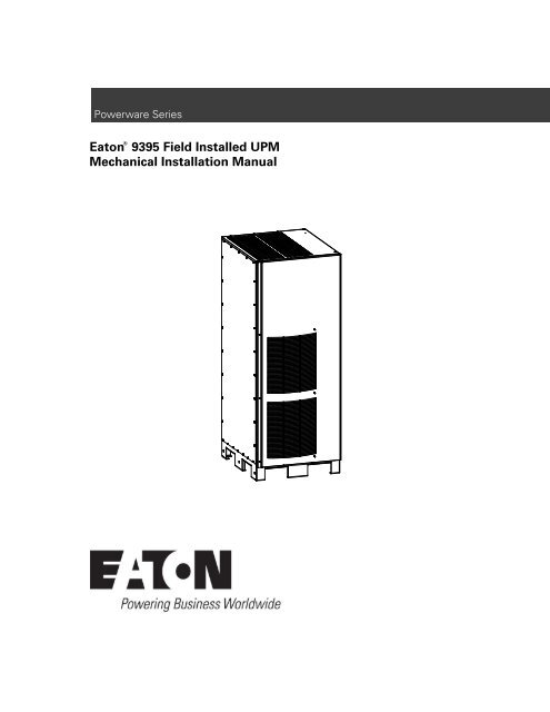
Powerware Series<br />
®<br />
<strong>Eaton</strong> <strong>9395</strong> <strong>Field</strong> <strong>Installed</strong> <strong>UPM</strong><br />
<strong>Mechanical</strong> Installation Manual
IMPORTANT SAFETY INSTRUCTIONS<br />
SAVE THESE INSTRUCTIONS<br />
This manual contains important instructions that you should follow during installation and maintenance of the UPS and batteries. Please<br />
read all instructions before operating the equipment and save this manual for future reference.<br />
CONSIGNES DE SÉCURITÉ IMPORTANTES<br />
CONSERVER CES INSTRUCTIONS<br />
Ce manuel comporte des instructions importantes que vous êtes invité à suivre lors de toute procédure d’installation et de maintenance<br />
des batteries et de l’onduleur. Veuillez consulter entièrement ces instructions avant de faire fonctionner l’équipement et conserver ce<br />
manuel afin de pouvoir vous y reporter ultérieurement.<br />
W A R N I N G<br />
This is a product for restricted sales distribution to informed partners (EN/IEC 62040−2). Installation restrictions or additional measures<br />
may be needed to prevent electromag<strong>net</strong>ic disturbances.<br />
<strong>Eaton</strong> is a registered trademark of <strong>Eaton</strong> Corporation or its subsidiaries and affiliates.<br />
Copyright 2008–2009 <strong>Eaton</strong> Corporation, Raleigh, NC, USA. All rights reserved. No part of this document may be reproduced in any way without<br />
the express written approval of <strong>Eaton</strong> Corporation.
Table of Contents<br />
1 Introduction . . . . . . . . . . . . . . . . . . . . . . . . . . . . . . . . . . . . . . . . . . . . . . . . . . . . . . . . . . . . . . . . . . . . . . . . . . . 1−1<br />
1.1 Using This Manual . . . . . . . . . . . . . . . . . . . . . . . . . . . . . . . . . . . . . . . . . . . . . . . . . . . . . . . . . . . . . . . . . . . . . . . . . . . . . . . . . . . . 1−1<br />
1.2 Conventions Used in This Manual . . . . . . . . . . . . . . . . . . . . . . . . . . . . . . . . . . . . . . . . . . . . . . . . . . . . . . . . . . . . . . . . . . . . . . . . . . 1−1<br />
1.3 Symbols, Controls, and Indicators . . . . . . . . . . . . . . . . . . . . . . . . . . . . . . . . . . . . . . . . . . . . . . . . . . . . . . . . . . . . . . . . . . . . . . . . . . 1−3<br />
1.4 For More Information . . . . . . . . . . . . . . . . . . . . . . . . . . . . . . . . . . . . . . . . . . . . . . . . . . . . . . . . . . . . . . . . . . . . . . . . . . . . . . . . . . . 1−4<br />
1.5 Getting Help . . . . . . . . . . . . . . . . . . . . . . . . . . . . . . . . . . . . . . . . . . . . . . . . . . . . . . . . . . . . . . . . . . . . . . . . . . . . . . . . . . . . . . . . . 1−4<br />
2 Safety Warnings . . . . . . . . . . . . . . . . . . . . . . . . . . . . . . . . . . . . . . . . . . . . . . . . . . . . . . . . . . . . . . . . . . . . . . . 2−1<br />
3 <strong>Field</strong> <strong>Installed</strong> <strong>UPM</strong> Installation Plan and Unpacking . . . . . . . . . . . . . . . . . . . . . . . . . . . . . . . . . . . . . . . . . . 3−1<br />
3.1 Creating an Installation Plan . . . . . . . . . . . . . . . . . . . . . . . . . . . . . . . . . . . . . . . . . . . . . . . . . . . . . . . . . . . . . . . . . . . . . . . . . . . . . . 3−1<br />
3.2 Preparing the Site . . . . . . . . . . . . . . . . . . . . . . . . . . . . . . . . . . . . . . . . . . . . . . . . . . . . . . . . . . . . . . . . . . . . . . . . . . . . . . . . . . . . . 3−1<br />
3.3 Inspecting and Unpacking the FI−<strong>UPM</strong> Cabi<strong>net</strong> . . . . . . . . . . . . . . . . . . . . . . . . . . . . . . . . . . . . . . . . . . . . . . . . . . . . . . . . . . . . . . . . . 3−5<br />
4 <strong>Field</strong> <strong>Installed</strong> <strong>UPM</strong> Installation . . . . . . . . . . . . . . . . . . . . . . . . . . . . . . . . . . . . . . . . . . . . . . . . . . . . . . . . . . . 4−1<br />
4.1 Preliminary Installation Information . . . . . . . . . . . . . . . . . . . . . . . . . . . . . . . . . . . . . . . . . . . . . . . . . . . . . . . . . . . . . . . . . . . . . . . . . 4−1<br />
4.2 Unloading the FI−<strong>UPM</strong> Cabi<strong>net</strong> from the Pallet . . . . . . . . . . . . . . . . . . . . . . . . . . . . . . . . . . . . . . . . . . . . . . . . . . . . . . . . . . . . . . . . . 4−1<br />
4.3 <strong>Mechanical</strong> Installation . . . . . . . . . . . . . . . . . . . . . . . . . . . . . . . . . . . . . . . . . . . . . . . . . . . . . . . . . . . . . . . . . . . . . . . . . . . . . . . . . 4−3<br />
4.4 Electrical Installation . . . . . . . . . . . . . . . . . . . . . . . . . . . . . . . . . . . . . . . . . . . . . . . . . . . . . . . . . . . . . . . . . . . . . . . . . . . . . . . . . . . 4−5<br />
4.5 Initial Startup . . . . . . . . . . . . . . . . . . . . . . . . . . . . . . . . . . . . . . . . . . . . . . . . . . . . . . . . . . . . . . . . . . . . . . . . . . . . . . . . . . . . . . . . 4−5<br />
4.6 Completing the Installation Checklist . . . . . . . . . . . . . . . . . . . . . . . . . . . . . . . . . . . . . . . . . . . . . . . . . . . . . . . . . . . . . . . . . . . . . . . . 4−5<br />
Warranty<br />
. . . . . . . . . . . . . . . . . . . . . . . . . . . . . . . . . . . . . . . . . . . . . . . . . . . . . . . . . . . . . . . . . . . . . . . . . . . . . . . .<br />
W−1<br />
EATON <strong>9395</strong> <strong>Field</strong> <strong>Installed</strong> <strong>UPM</strong> <strong>Mechanical</strong> Installation Manual 164201717 Rev 3 www.eaton.com/powerquality<br />
i
TABLE OF CONTENTS<br />
List of Figures<br />
Figure 1-1. Powerware <strong>9395</strong> <strong>Field</strong> <strong>Installed</strong> <strong>UPM</strong> . . . . . . . . . . . . . . . . . . . . . . . . . . . . . . . . . . . . . . . . . . . . . . . . . . . . . . . . . . . . . .<br />
Figure 3-1. FI−<strong>UPM</strong> Cabi<strong>net</strong> Dimensions (Front View) . . . . . . . . . . . . . . . . . . . . . . . . . . . . . . . . . . . . . . . . . . . . . . . . . . . . . . . . . . .<br />
Figure 3-2. FI−<strong>UPM</strong> Cabi<strong>net</strong> Dimensions (Right Side View) . . . . . . . . . . . . . . . . . . . . . . . . . . . . . . . . . . . . . . . . . . . . . . . . . . . . . . .<br />
Figure 3-3. FI−<strong>UPM</strong> Cabi<strong>net</strong> Dimensions (Top View) . . . . . . . . . . . . . . . . . . . . . . . . . . . . . . . . . . . . . . . . . . . . . . . . . . . . . . . . . . . .<br />
Figure 3-4. FI−<strong>UPM</strong> Cabi<strong>net</strong> Dimensions (Bottom View) . . . . . . . . . . . . . . . . . . . . . . . . . . . . . . . . . . . . . . . . . . . . . . . . . . . . . . . . . .<br />
Figure 3-5. FI−<strong>UPM</strong> Cabi<strong>net</strong> Dimensions (Bottom View with Mounting Brackets) . . . . . . . . . . . . . . . . . . . . . . . . . . . . . . . . . . . . . . . .<br />
Figure 3-6. FI−<strong>UPM</strong> Cabi<strong>net</strong> Center of Gravity . . . . . . . . . . . . . . . . . . . . . . . . . . . . . . . . . . . . . . . . . . . . . . . . . . . . . . . . . . . . . . . .<br />
Figure 3-7. Powerware <strong>9395</strong> FI−<strong>UPM</strong> Cabi<strong>net</strong> as Shipped on Pallet . . . . . . . . . . . . . . . . . . . . . . . . . . . . . . . . . . . . . . . . . . . . . . . . .<br />
Figure 4-1. Removing the Left Side Shipping Bracket . . . . . . . . . . . . . . . . . . . . . . . . . . . . . . . . . . . . . . . . . . . . . . . . . . . . . . . . . . .<br />
Figure 4-2. Removing the Right Side Shipping Bracket . . . . . . . . . . . . . . . . . . . . . . . . . . . . . . . . . . . . . . . . . . . . . . . . . . . . . . . . . .<br />
Figure 4-3. UPS Cabi<strong>net</strong> Wire Entry Plate and Knockout Locations . . . . . . . . . . . . . . . . . . . . . . . . . . . . . . . . . . . . . . . . . . . . . . . . . .<br />
1−2<br />
3−3<br />
3−3<br />
3−4<br />
3−4<br />
3−4<br />
3−5<br />
3−6<br />
4−2<br />
4−3<br />
4−4<br />
ii<br />
EATON <strong>9395</strong> <strong>Field</strong> <strong>Installed</strong> <strong>UPM</strong> <strong>Mechanical</strong> Installation Manual 164201717 Rev 3 www.eaton.com/powerquality
Chapter 1<br />
Figure 1Table 1<br />
Introduction<br />
The <strong>Eaton</strong> ® <strong>9395</strong> <strong>Field</strong> <strong>Installed</strong> <strong>UPM</strong> (FI−<strong>UPM</strong>) provides increased capacity or N+1<br />
redundancy for <strong>Eaton</strong> <strong>9395</strong> UPS systems. Capacity increase depends on the<br />
capabilities of the originally installed system. The FI−<strong>UPM</strong> may be installed at any time<br />
when power needs change. The module cabi<strong>net</strong> installs on the left side of the UPS<br />
cabi<strong>net</strong> and wires directly to the UPS. No input or output wiring changes are needed<br />
for a capacity increase if the original installation was wired with increased capacity in<br />
mind. Operation remains the same as the original UPS.<br />
The FI−<strong>UPM</strong> is housed in a single, free-standing cabi<strong>net</strong> with safety shields behind the<br />
front panel for hazardous voltage protection. The cabi<strong>net</strong> matches the UPS cabi<strong>net</strong> in<br />
style and color. Figure 1-1 shows the <strong>Eaton</strong> <strong>9395</strong> FI−<strong>UPM</strong>.<br />
NOTE Wiring, startup, and operational checks must be performed by an authorized <strong>Eaton</strong> Customer Service<br />
Engineer, or the warranty terms specified on page W−1 become void. This service is offered as part of the<br />
sales contract for the FI−<strong>UPM</strong>. Contact an <strong>Eaton</strong> service representative in advance (usually a two−week notice<br />
is required) to request service.<br />
1.1 Using This Manual<br />
This manual describes how to mechanically install the <strong>Eaton</strong> <strong>9395</strong> FI−<strong>UPM</strong> cabi<strong>net</strong>.<br />
Electrical installation will be performed by an <strong>Eaton</strong> Customer Service Engineer. Read<br />
and understand the procedures described in this manual to ensure trouble−free<br />
installation.<br />
1.2 Conventions Used in This Manual<br />
This manual uses these type conventions:<br />
Bold type highlights important concepts in discussions, key terms in procedures,<br />
and menu options, or represents a command or option that you type or enter at a<br />
prompt.<br />
Italic type highlights notes and new terms where they are defined.<br />
Screen type represents information that appears on the screen or LCD.<br />
Icon<br />
Description<br />
Information notes call attention to important features or instructions.<br />
[Keys]<br />
Brackets are used when referring to a specific key, such as [Enter] or [Ctrl].<br />
In this manual, the term UPS refers only to the UPS cabi<strong>net</strong> and its internal elements.<br />
The term UPS system refers to the entire power protection system – the UPS<br />
cabi<strong>net</strong>, the battery cabi<strong>net</strong>, and options or accessories installed.<br />
EATON <strong>9395</strong> <strong>Field</strong> <strong>Installed</strong> <strong>UPM</strong> <strong>Mechanical</strong> Installation Manual 164201717 Rev 3 www.eaton.com/powerquality<br />
1−1
INTRODUCTION<br />
Figure 1-1. <strong>Eaton</strong> <strong>9395</strong> <strong>Field</strong> <strong>Installed</strong> <strong>UPM</strong><br />
1−2<br />
EATON <strong>9395</strong> <strong>Field</strong> <strong>Installed</strong> <strong>UPM</strong> <strong>Mechanical</strong> Installation Manual 164201717 Rev 3 www.eaton.com/powerquality
INTRODUCTION<br />
1.3 Symbols, Controls, and Indicators<br />
The following are examples of symbols used on the UPS or accessories to alert you<br />
to important information:<br />
RISK OF ELECTRIC SHOCK − Observe the warning associated with the risk of electric<br />
shock symbol.<br />
CAUTION: REFER TO OPERATOR’S MANUAL − Refer to your operator’s manual for<br />
additional information, such as important operating and maintenance instructions.<br />
This symbol indicates that you should not discard the UPS or the UPS batteries in the<br />
trash. This product contains sealed, lead-acid batteries and must be disposed of<br />
properly. For more information, contact your local recycling/reuse or hazardous waste<br />
center.<br />
This symbol indicates that you should not discard waste electrical or electronic<br />
equipment (WEEE) in the trash. For proper disposal, contact your local recycling/reuse<br />
or hazardous waste center.<br />
1.4 For More Information<br />
Refer to the followong manuals for additional information:<br />
<strong>Eaton</strong> <strong>9395</strong> UPS (225–275 kVA) Installation and Operation Manual<br />
<strong>Eaton</strong> <strong>9395</strong> UPS (300 kVA) Installation and Operation Manual<br />
<strong>Eaton</strong> <strong>9395</strong> 550/275 UPS (225–550 kVA) Installation and Operation Manual<br />
<strong>Eaton</strong> <strong>9395</strong> UPS and Plus 1 UPS (450–550 kVA) Installation and Operation Manual<br />
<strong>Eaton</strong> <strong>9395</strong> UPS and Plus 1 UPS (650–825 kVA) Installation and Operation Manual<br />
<strong>Eaton</strong> <strong>9395</strong> UPS (1000–1100 kVA) Installation and Operation Manual<br />
These manuals describe:<br />
UPS cabi<strong>net</strong>, optional components, and accessory installation instructions,<br />
including site preparation, planning for installation, and wiring and safety<br />
information. Detailed illustrations of cabi<strong>net</strong>s and optional accessories with<br />
dimensional and connection point drawings are provided.<br />
UPS operation, including UPS cabi<strong>net</strong> controls, functions of the UPS, standard<br />
features and optional accessories, procedures for starting and stopping the UPS,<br />
and information about maintenance and responding to system events.<br />
Communication capabilities of the UPS system.<br />
Visit www.eaton.com/powerquality or contact <strong>Eaton</strong> service representative for<br />
information on how to obtain copies of these manuals.<br />
EATON <strong>9395</strong> <strong>Field</strong> <strong>Installed</strong> <strong>UPM</strong> <strong>Mechanical</strong> Installation Manual 164201717 Rev 3 www.eaton.com/powerquality<br />
1−3
INTRODUCTION<br />
1.5 Getting Help<br />
If help is needed with any of the following:<br />
Scheduling initial startup<br />
Regional locations and telephone numbers<br />
A question about any of the information in this manual<br />
A question this manual does not answer<br />
Please call the <strong>Eaton</strong> Help Desk at:<br />
United States: 1−800−843−9433 or 1−919−870−3028<br />
Canada: 1−800−461−9166 ext 260<br />
All other countries: Call your local service representative<br />
1−4<br />
EATON <strong>9395</strong> <strong>Field</strong> <strong>Installed</strong> <strong>UPM</strong> <strong>Mechanical</strong> Installation Manual 164201717 Rev 3 www.eaton.com/powerquality
Chapter 2<br />
Figure 2Table 2<br />
Safety Warnings<br />
IMPORTANT SAFETY INSTRUCTIONS<br />
SAVE THESE INSTRUCTIONS<br />
This manual contains important instructions that should be followed during installation of the <strong>Field</strong> <strong>Installed</strong><br />
<strong>UPM</strong> (FI−<strong>UPM</strong> ). Read all instructions before operating the equipment and save this manual for future<br />
reference.<br />
The FI−<strong>UPM</strong> cabi<strong>net</strong> is designed for industrial or computer room applications, and contains safety shields<br />
behind the panel. However, the FI−<strong>UPM</strong> is a sophisticated power system and should be handled with<br />
appropriate care.<br />
D A N G E R<br />
The FI−<strong>UPM</strong> contains LETHAL VOLTAGES. All repairs and service should be performed by AUTHORIZED<br />
SERVICE PERSONNEL ONLY. There are NO USER SERVICEABLE PARTS inside the FI−<strong>UPM</strong>.<br />
W A R N I N G<br />
The UPS system contains its own energy source (batteries). The output terminals may carry live voltage<br />
even when the UPS is disconnected from an AC source.<br />
To reduce the risk of fire or electric shock, install this UPS and FI−<strong>UPM</strong> in a temperature and humidity<br />
controlled, indoor environment, free of conductive contaminants. Ambient temperature must not exceed<br />
40°C (104°F). Do not operate near water or excessive humidity (95% maximum). The system is not<br />
intended for outdoor use.<br />
Ensure all power is disconnected before performing installation or service.<br />
ELECTRIC ENERGY HAZARD. Do not attempt to alter any battery wiring or connectors. Attempting to alter<br />
wiring can cause injury.<br />
C A U T I O N<br />
Keep the FI−<strong>UPM</strong> front panel installed to ensure proper cooling airflow and to protect personnel from<br />
dangerous voltages inside the unit.<br />
Do not install or operate the UPS system or FI−<strong>UPM</strong> close to gas or electric heat sources.<br />
The operating environment should be maintained within the parameters stated in this manual.<br />
Keep surroundings uncluttered, clean, and free from excess moisture.<br />
Observe all DANGER, CAUTION, and WARNING notices affixed to the inside and outside of the<br />
equipment.<br />
EATON <strong>9395</strong> <strong>Field</strong> <strong>Installed</strong> <strong>UPM</strong> <strong>Mechanical</strong> Installation Manual 164201717 Rev 3 www.eaton.com/powerquality<br />
2−1
SAFETY WARNINGS<br />
This page intentionally left blank.<br />
2−2<br />
EATON <strong>9395</strong> <strong>Field</strong> <strong>Installed</strong> <strong>UPM</strong> <strong>Mechanical</strong> Installation Manual 164201717 Rev 3 www.eaton.com/powerquality
Chapter 3<br />
Figure 3Table 3<br />
<strong>Field</strong> <strong>Installed</strong> <strong>UPM</strong> Installation Plan and Unpacking<br />
Use the following basic sequence of steps to install the <strong>Field</strong> <strong>Installed</strong> <strong>UPM</strong> (FI−<strong>UPM</strong>):<br />
1. Create an installation plan for the FI−<strong>UPM</strong> (Chapter 3).<br />
2. Prepare your site for the FI−<strong>UPM</strong> (Chapter 3).<br />
3. Inspect and unpack the FI−<strong>UPM</strong> cabi<strong>net</strong> (Chapter 3).<br />
4. Unload and install the FI−<strong>UPM</strong> cabi<strong>net</strong> (Chapter 4).<br />
5. Complete the Installation Checklist (Chapter 4).<br />
6. Have authorized service personnel install wiring, perform preliminary operational<br />
checks, and start up the system.<br />
NOTE Wiring, startup, and operational checks must be performed by an authorized <strong>Eaton</strong> Customer Service<br />
Engineer, or the warranty terms specified on page W−1 become void. This service is offered as part of the<br />
sales contract for the FI−<strong>UPM</strong>. Contact an <strong>Eaton</strong> service representative in advance (usually a two−week notice<br />
is required) to request service.<br />
3.1 Creating an Installation Plan<br />
Before installing the FI−<strong>UPM</strong>, read and understand how this manual applies to the<br />
system being installed. Use the procedures and illustrations in paragraph 3.2 and<br />
Chapter 4 to create a logical plan for installing the system.<br />
3.2 Preparing the Site<br />
For the FI−<strong>UPM</strong> to operate at peak efficiency, the installation site should meet the<br />
environmental parameters outlined in this manual. If the FI−<strong>UPM</strong> is to be operated at<br />
an altitude higher than 1500m (5000 ft) for the 480V model or 1000m (3330 ft) for the<br />
400V model , contact an <strong>Eaton</strong> service representative for important information about<br />
high altitude operation. The operating environment must meet the weight, clearance,<br />
and environmental requirements specified.<br />
The FI−<strong>UPM</strong> installation must meet the following guidelines:<br />
The system must be installed on a level floor suitable for computer or electronic<br />
equipment.<br />
The system must be installed in a temperature and humidity controlled indoor area<br />
free of conductive contaminants.<br />
The cabi<strong>net</strong> must be installed in line-up-and-match configuration.<br />
Failure to follow guidelines may void your warranty.<br />
EATON <strong>9395</strong> <strong>Field</strong> <strong>Installed</strong> <strong>UPM</strong> <strong>Mechanical</strong> Installation Manual 164201717 Rev 3 www.eaton.com/powerquality<br />
3−1
FIELD INSTALLED <strong>UPM</strong> INSTALLATION PLAN AND UNPACKING<br />
The FI−<strong>UPM</strong> operating environment must meet the weight requirements shown in<br />
Table 3-1 and the size requirements shown in Figure 3-1 through Figure 3-6.<br />
Dimensions are in millimeters (inches).<br />
Table 3-1. FI−<strong>UPM</strong> Cabi<strong>net</strong> Weight<br />
Model<br />
Shipping<br />
Weight<br />
kg (lb)<br />
<strong>Installed</strong><br />
<strong>Eaton</strong> <strong>9395</strong> FI−<strong>UPM</strong> 642 (1415.4) 606 (1336)<br />
The FI−<strong>UPM</strong> cabi<strong>net</strong> uses forced air cooling to regulate internal component<br />
temperature. Air inlets are in the front of the cabi<strong>net</strong> and outlets are in the top. Allow<br />
clearance in front of and above each cabi<strong>net</strong> for proper air circulation. The clearances<br />
required around the FI−<strong>UPM</strong> cabi<strong>net</strong> are shown in Table 3-2.<br />
Table 3-2. FI−<strong>UPM</strong> Cabi<strong>net</strong> Clearances<br />
From Top of Cabi<strong>net</strong><br />
457.2 mm (18") minimum clearance for ventilation<br />
From Front of Cabi<strong>net</strong><br />
From Back of Cabi<strong>net</strong><br />
From Right Side of Cabi<strong>net</strong><br />
From Left Side of Cabi<strong>net</strong><br />
914.4 mm (36") working space<br />
None Required<br />
None Required<br />
None Required<br />
The basic environmental requirements for operation of the FI−<strong>UPM</strong> are:<br />
Ambient Temperature Range: 0–40°C (32–104°F)<br />
Recommended Operating Range: 20–25°C (68–77°F)<br />
Maximum Relative Humidity: 95%, noncondensing<br />
The FI−<strong>UPM</strong> ventilation requirements are shown in Table 3-3.<br />
Table 3-3. FI−<strong>UPM</strong> Air Conditioning or Ventilation Requirements During Full Load Operation<br />
Rating<br />
Input/Output Voltage<br />
Heat Rejection<br />
BTU/hr 1000 (kg−cal/hr)<br />
Ventilation Required for<br />
Cooling Air Exhaust<br />
225 kVA<br />
275 kVA<br />
300 kVA<br />
400/400 43 (10943)<br />
480/480 44 (11054)<br />
400/400 53 (13375)<br />
480/480 54 (13510)<br />
400/400 51 (12969)<br />
480/480 51 (12969)<br />
Approximately<br />
755 liter/sec<br />
(1600 cfm)<br />
3−2<br />
EATON <strong>9395</strong> <strong>Field</strong> <strong>Installed</strong> <strong>UPM</strong> <strong>Mechanical</strong> Installation Manual 164201717 Rev 3 www.eaton.com/powerquality
FIELD INSTALLED <strong>UPM</strong> INSTALLATION PLAN AND UNPACKING<br />
1871.5<br />
[73.7]<br />
732<br />
[28.8]<br />
Dimensions are in millimeters [inches].<br />
Figure 3-1. FI−<strong>UPM</strong> Cabi<strong>net</strong> Dimensions (Front View)<br />
39.5<br />
[1.6]<br />
831.5<br />
[32.7]<br />
149.2<br />
[5.9]<br />
192.4<br />
[7.6]<br />
871<br />
[34.3]<br />
Dimensions are in millimeters [inches].<br />
Figure 3-2. FI−<strong>UPM</strong> Cabi<strong>net</strong> Dimensions (Right Side View)<br />
EATON <strong>9395</strong> <strong>Field</strong> <strong>Installed</strong> <strong>UPM</strong> <strong>Mechanical</strong> Installation Manual 164201717 Rev 3 www.eaton.com/powerquality<br />
3−3
FIELD INSTALLED <strong>UPM</strong> INSTALLATION PLAN AND UNPACKING<br />
37<br />
[1.5]<br />
34<br />
[1.4]<br />
475.4<br />
[18.7]<br />
758.8<br />
[20]<br />
Front<br />
Figure 3-3. FI−<strong>UPM</strong> Cabi<strong>net</strong> Dimensions (Top View)<br />
Dimensions are in millimeters [inches].<br />
Front<br />
213<br />
[8.4]<br />
602.8<br />
[23.7]<br />
Figure 3-4. FI−<strong>UPM</strong> Cabi<strong>net</strong> Dimensions (Bottom View)<br />
Dimensions are in millimeters [inches].<br />
59.2<br />
[2.4]<br />
69<br />
[2.7]<br />
39.2<br />
[1.54]<br />
848<br />
[33.4]<br />
808<br />
[31.8]<br />
730<br />
[28.7]<br />
Front<br />
830<br />
[32.7]<br />
346<br />
[13.6]<br />
346<br />
[13.6]<br />
12.7 [0.5] X 15.8 [0.62] Slot (6X)<br />
Dimensions are in millimeters [inches].<br />
Figure 3-5. FI−<strong>UPM</strong> Cabi<strong>net</strong> Dimensions (Bottom View with Mounting Brackets)<br />
3−4<br />
EATON <strong>9395</strong> <strong>Field</strong> <strong>Installed</strong> <strong>UPM</strong> <strong>Mechanical</strong> Installation Manual 164201717 Rev 3 www.eaton.com/powerquality
FIELD INSTALLED <strong>UPM</strong> INSTALLATION PLAN AND UNPACKING<br />
1871.5<br />
[73.7]<br />
CG<br />
CG<br />
924<br />
[36.4]<br />
300<br />
[11.8]<br />
732<br />
[28.8]<br />
434<br />
[17.1]<br />
Figure 3-6. FI−<strong>UPM</strong> Cabi<strong>net</strong> Center of Gravity<br />
830<br />
[32.7]<br />
Dimensions are in millimeters [inches].<br />
3.3 Inspecting and Unpacking the FI−<strong>UPM</strong> Cabi<strong>net</strong><br />
The FI−<strong>UPM</strong> cabi<strong>net</strong> is palleted separately for shipping. The cabi<strong>net</strong> is shipped bolted<br />
to a wooden pallet and protected with outer protective packaging material (see<br />
Figure 3-7).<br />
W A R N I N G<br />
The FI−<strong>UPM</strong> cabi<strong>net</strong> is heavy (see Table 3-1 on page 3−2). If unpacking and unloading instructions are not<br />
closely followed, the cabi<strong>net</strong> may tip and cause serious injury.<br />
1. Carefully inspect the outer packaging for evidence of damage during transit.<br />
C A U T I O N<br />
Do not install a damaged cabi<strong>net</strong>. Report any damage to the carrier and contact an <strong>Eaton</strong> service<br />
representative immediately.<br />
NOTE For the following step, verify that the forklift or pallet jack is rated to handle the weight of the<br />
cabi<strong>net</strong> (see Table 3-1 on page 3−2 for cabi<strong>net</strong> weight).<br />
2. Use a forklift or pallet jack to move the packaged cabi<strong>net</strong> to the installation site,<br />
or as close as possible, before unpacking. If possible, move the cabi<strong>net</strong> using the<br />
pallet. Insert the forklift or pallet jack forks from the right side of the pallet (facing<br />
the cabi<strong>net</strong>), between the supports on the bottom of the pallet (see Figure 3-6<br />
for the FI−<strong>UPM</strong> cabi<strong>net</strong> center of gravity measurements).<br />
EATON <strong>9395</strong> <strong>Field</strong> <strong>Installed</strong> <strong>UPM</strong> <strong>Mechanical</strong> Installation Manual 164201717 Rev 3 www.eaton.com/powerquality<br />
3−5
FIELD INSTALLED <strong>UPM</strong> INSTALLATION PLAN AND UNPACKING<br />
C A U T I O N<br />
Do not tilt the FI−<strong>UPM</strong> cabi<strong>net</strong> more than 10° from vertical or the cabi<strong>net</strong> may tip over.<br />
3. Set the pallet on a firm, level surface, allowing a minimum clearance of 3m (10 ft)<br />
on each side for removing the cabi<strong>net</strong> from the pallet.<br />
NOTE The FI−<strong>UPM</strong> cabi<strong>net</strong> is shipped with a debris shield covering the ventilation grill on top of the unit.<br />
Do not remove the debris shield until installation is complete.<br />
4. Remove the protective covering from the cabi<strong>net</strong>.<br />
5. Remove the packing material, and discard or recycle in a responsible manner.<br />
6. Inspect the contents for any evidence of physical damage, and compare each<br />
item with the Bill of Lading. If damage has occurred or shortages are evident,<br />
contact an <strong>Eaton</strong> service representative immediately to determine the extent of<br />
the damage and its impact on further installation.<br />
NOTE While waiting for installation, protect the unpacked cabi<strong>net</strong> from moisture, dust, and other harmful<br />
contaminants. Failure to store and protect the FI−<strong>UPM</strong> properly may void your warranty.<br />
Figure 3-7. <strong>Eaton</strong> <strong>9395</strong> FI−<strong>UPM</strong> Cabi<strong>net</strong> as Shipped on Pallet<br />
3−6<br />
EATON <strong>9395</strong> <strong>Field</strong> <strong>Installed</strong> <strong>UPM</strong> <strong>Mechanical</strong> Installation Manual 164201717 Rev 3 www.eaton.com/powerquality
Chapter 4<br />
Figure 4Table 4<br />
<strong>Field</strong> <strong>Installed</strong> <strong>UPM</strong> Installation<br />
4.1 Preliminary Installation Information<br />
W A R N I N G<br />
Installation should be performed only by qualified personnel.<br />
Refer to the following while installing the <strong>Field</strong> <strong>Installed</strong> <strong>UPM</strong> (FI−<strong>UPM</strong>):<br />
Chapter 3 for cabi<strong>net</strong> dimensions, equipment weight, wiring and terminal data, and<br />
installation notes.<br />
Do not tilt the cabi<strong>net</strong> more than 10° during installation.<br />
The FI−<strong>UPM</strong> cabi<strong>net</strong> is installed on the left side of the UPS cabi<strong>net</strong>.<br />
The FI−<strong>UPM</strong> cabi<strong>net</strong> is shipped with a debris shield covering the ventilation grill on<br />
top of the unit. Do not remove the debris shield until installation is complete.<br />
However, remove the shield before operating the UPS system. Once the debris<br />
shield is removed, do not place objects on the ventilation grill.<br />
A FI−<strong>UPM</strong> is always designated as <strong>UPM</strong> 4.<br />
4.2 Unloading the FI−<strong>UPM</strong> Cabi<strong>net</strong> from the Pallet<br />
The FI−<strong>UPM</strong> cabi<strong>net</strong> is bolted to a wooden pallet supported by wood skids. To remove<br />
the pallet:<br />
W A R N I N G<br />
The FI−<strong>UPM</strong> cabi<strong>net</strong> is heavy (see Table 3-1 on page 3−2). If unpacking and unloading instructions are not<br />
closely followed, the cabi<strong>net</strong> may tip and cause serious injury.<br />
C A U T I O N<br />
Do not tilt cabi<strong>net</strong>s more than 10° from vertical.<br />
Lift the cabi<strong>net</strong> only with a forklift or damage may occur.<br />
NOTE For the following steps, verify that the forklift or pallet jack is rated to handle the weight of the<br />
cabi<strong>net</strong> (see Table 3-1 on page 3−2 for cabi<strong>net</strong> weight).<br />
1. If not already accomplished, use a forklift or pallet jack to move the cabi<strong>net</strong> to the<br />
installation area, or as close as possible, before unloading from the pallet. If<br />
possible, move the cabi<strong>net</strong> using the pallet. Insert the forklift or pallet jack forks<br />
from the right side of the pallet (facing the cabi<strong>net</strong>), between the supports on the<br />
bottom of the pallet (see Figure 3-6 on page 3−5 for the FI−<strong>UPM</strong> cabi<strong>net</strong> center of<br />
gravity measurements).<br />
2. Remove the three bolts securing the left side shipping bracket to the cabi<strong>net</strong> and<br />
three bolts securing the bracket to the pallet (see Figure 4-1). Remove the left<br />
side shipping bracket. If installing the cabi<strong>net</strong> permanently, retain the shipping<br />
bracket and securing hardware for later use.<br />
EATON <strong>9395</strong> <strong>Field</strong> <strong>Installed</strong> <strong>UPM</strong> <strong>Mechanical</strong> Installation Manual 164201717 Rev 3 www.eaton.com/powerquality<br />
4−1
FIELD INSTALLED <strong>UPM</strong> INSTALLATION<br />
FI−<strong>UPM</strong> Removable<br />
Front Panel<br />
Shipping Bracket<br />
Bolts<br />
Pallet<br />
Shipping Bracket<br />
Bolts<br />
Left Side Shipping<br />
Bracket<br />
Figure 4-1. Removing the Left Side Shipping Bracket<br />
3. Remove the three bolts securing the right side shipping bracket to the cabi<strong>net</strong><br />
and three bolts securing the bracket to the pallet (see Figure 4-2). Remove the<br />
right side shipping bracket.<br />
4. Using a forklift, raise the FI−<strong>UPM</strong> cabi<strong>net</strong> section until the cabi<strong>net</strong> bottom clears<br />
the pallet by approximately 3 mm (1/8").<br />
5. Pull the pallet from under the FI−<strong>UPM</strong> cabi<strong>net</strong>.<br />
6. Discard or recycle the pallet and unused shipping brackets in a responsible<br />
manner.<br />
7. Carefully lower the FI−<strong>UPM</strong> cabi<strong>net</strong> until the cabi<strong>net</strong> base contacts the floor.<br />
4−2<br />
EATON <strong>9395</strong> <strong>Field</strong> <strong>Installed</strong> <strong>UPM</strong> <strong>Mechanical</strong> Installation Manual 164201717 Rev 3 www.eaton.com/powerquality
FIELD INSTALLED <strong>UPM</strong> INSTALLATION<br />
FI−<strong>UPM</strong> Removable<br />
Front Panel<br />
Shipping Bracket<br />
Bolts<br />
Pallet<br />
Right Side Shipping<br />
Bracket<br />
Figure 4-2. Removing the Right Side Shipping Bracket<br />
Shipping Bracket<br />
Bolts<br />
4.3 <strong>Mechanical</strong> Installation<br />
To mechanically install the FI−<strong>UPM</strong>:<br />
1. Remove the wire entry plate located on the bottom left side of the UPS cabi<strong>net</strong><br />
(see Figure 4-3).<br />
2. If not already removed, remove the wire entry knockout located on the top left<br />
side of the UPS cabi<strong>net</strong> (see Figure 4-3).<br />
3. Locate the hardware kit (packed inside of the cabi<strong>net</strong>). Locate the nylon grommet<br />
from the hardware kit. If not already installed, install the nylon grommet in the<br />
knockout hole.<br />
4. Using a forklift, move the FI−<strong>UPM</strong> cabi<strong>net</strong> to the final installed location on the left<br />
side of the UPS cabi<strong>net</strong>. Verify that the FI−<strong>UPM</strong> cabi<strong>net</strong> right side is against the<br />
UPS cabi<strong>net</strong> left side and the front panels are flush with each other.<br />
5. Carefully lower the FI−<strong>UPM</strong> cabi<strong>net</strong> until the cabi<strong>net</strong> base contacts the floor.<br />
NOTE A flat cabi<strong>net</strong> joining bracket is provided for securing the cabi<strong>net</strong>s at the top front (see Step 7).<br />
6. Remove and retain one top screw and two bottom screws securing the FI−<strong>UPM</strong><br />
front panel (see Figure 4-2). Lift the panel straight up to remove it from the panel<br />
hanger bracket at the top of the cabi<strong>net</strong>.<br />
EATON <strong>9395</strong> <strong>Field</strong> <strong>Installed</strong> <strong>UPM</strong> <strong>Mechanical</strong> Installation Manual 164201717 Rev 3 www.eaton.com/powerquality<br />
4−3
FIELD INSTALLED <strong>UPM</strong> INSTALLATION<br />
7. Locate the small flat bracket and screws from the hardware kit. Align the holes in<br />
the small flat bracket over holes in the top of the FI−<strong>UPM</strong> and UPS cabi<strong>net</strong>s.<br />
Secure the bracket with the screws from the hardware kit.<br />
8. Reinstall the FI−<strong>UPM</strong> front panel removed in Step 6, and secure with the retained<br />
hardware.<br />
9. If permanently mounting the system, proceed to Step 10; otherwise, continue to<br />
Step 12.<br />
10. Using the retained hardware, reinstall the left shipping bracket removed in<br />
paragraph 4.2, Step 2 on page 4−1 to the left side of the FI−<strong>UPM</strong> cabi<strong>net</strong> with<br />
the angle facing outward (see Figure 4-1 on page 4−2).<br />
11. Secure the cabi<strong>net</strong> to the floor with customer−supplied hardware.<br />
12. Proceed to paragraph 4.4.<br />
Wire entry knockout. Remove knockout to<br />
route wires between cabi<strong>net</strong>s. (Install nylon<br />
grommet after removal of knockout.)<br />
UPS Front<br />
Wire Entry Plate Remove plate to<br />
route wires between cabi<strong>net</strong>s.<br />
LEFT SIDE VIEW<br />
Figure 4-3. UPS Cabi<strong>net</strong> Wire Entry Plate and Knockout Locations<br />
4−4<br />
EATON <strong>9395</strong> <strong>Field</strong> <strong>Installed</strong> <strong>UPM</strong> <strong>Mechanical</strong> Installation Manual 164201717 Rev 3 www.eaton.com/powerquality
FIELD INSTALLED <strong>UPM</strong> INSTALLATION<br />
4.4 Electrical Installation<br />
Install FI−<strong>UPM</strong> battery wiring from the battery cabi<strong>net</strong> to the FI−<strong>UPM</strong> battery terminal<br />
location in the UPS (refer to the applicable UPS manual listed in paragraph 1.4 on<br />
page 1−3). Wiring between the FI−<strong>UPM</strong> and the UPS, and FI−<strong>UPM</strong> battery terminals<br />
will be installed by an <strong>Eaton</strong> Customer Service Engineer. This service is offered as<br />
part of the sales contract for the FI−<strong>UPM</strong>. Contact an <strong>Eaton</strong> service representative in<br />
advance (usually a two−week notice is required) to request service.<br />
4.5 Initial Startup<br />
Startup and operational checks must be performed by an authorized <strong>Eaton</strong> Customer<br />
Service Engineer, or the warranty terms specified on page W−1 become void. This<br />
service is offered as part of the sales contract for the FI−<strong>UPM</strong>. Contact an <strong>Eaton</strong><br />
service representative in advance (usually a two−week notice is required) to reserve a<br />
preferred startup date.<br />
4.6 Completing the Installation Checklist<br />
The final step in installing the FI−<strong>UPM</strong> is completing the following Installation<br />
Checklist. This checklist ensures that all hardware, cables, and other equipment have<br />
been completely installed. Complete all items listed on the checklist to ensure a<br />
smooth installation. Make a copy of the Installation Checklist before filling it out, and<br />
retain the original.<br />
After the installation is complete, an <strong>Eaton</strong> Customer Service Engineer must verify<br />
the operation of the FI−<strong>UPM</strong> and UPS system and commission it to support the critical<br />
load. The service representative will verify software and operating setup parameters.<br />
Service personnel may request a copy of the completed Installation Checklist to verify<br />
all applicable equipment installations have been completed.<br />
NOTE The Installation Checklist MUST be completed prior to starting the FI−<strong>UPM</strong> and UPS system for the<br />
first time.<br />
EATON <strong>9395</strong> <strong>Field</strong> <strong>Installed</strong> <strong>UPM</strong> <strong>Mechanical</strong> Installation Manual 164201717 Rev 3 www.eaton.com/powerquality<br />
4−5
FIELD INSTALLED <strong>UPM</strong> INSTALLATION<br />
Installation Checklist<br />
<br />
All packing materials and restraints have been removed from the cabi<strong>net</strong>.<br />
<br />
<br />
<br />
<br />
<br />
<br />
<br />
<br />
<br />
<br />
<br />
UPS cabi<strong>net</strong> wire entry plate and knockout have been removed from the cabi<strong>net</strong>.<br />
The FI−<strong>UPM</strong> cabi<strong>net</strong> is placed in its installed location.<br />
A cabi<strong>net</strong> grounding/mounting kit is installed between the FI−<strong>UPM</strong> and UPS cabi<strong>net</strong>s.<br />
All cables are properly routed from the FI−<strong>UPM</strong> to the UPS.<br />
Air conditioning equipment is installed and operating correctly.<br />
The area around the installed UPS system is clean and dust-free. (It is recommended that the UPS be installed on a<br />
level floor suitable for computer or electronic equipment.)<br />
Adequate workspace exists around the FI−<strong>UPM</strong> and UPS cabi<strong>net</strong>s.<br />
Adequate lighting is provided around all UPS equipment.<br />
A 120 Vac or 230 Vac service outlet (depending on local mains voltage) is located within 7.5 meters (25 feet) of the<br />
UPS equipment.<br />
The debris shield covering the FI−<strong>UPM</strong> cabi<strong>net</strong> ventilation grill is removed.<br />
Startup and operational checks are performed by an authorized <strong>Eaton</strong> Customer Service Engineer.<br />
4−6<br />
EATON <strong>9395</strong> <strong>Field</strong> <strong>Installed</strong> <strong>UPM</strong> <strong>Mechanical</strong> Installation Manual 164201717 Rev 3 www.eaton.com/powerquality
FIELD INSTALLED <strong>UPM</strong> INSTALLATION<br />
Notes<br />
_________________________________________________________________________<br />
_________________________________________________________________________<br />
_________________________________________________________________________<br />
_________________________________________________________________________<br />
_________________________________________________________________________<br />
_________________________________________________________________________<br />
_________________________________________________________________________<br />
_________________________________________________________________________<br />
_________________________________________________________________________<br />
_________________________________________________________________________<br />
_________________________________________________________________________<br />
_________________________________________________________________________<br />
_________________________________________________________________________<br />
_________________________________________________________________________<br />
_________________________________________________________________________<br />
_________________________________________________________________________<br />
EATON <strong>9395</strong> <strong>Field</strong> <strong>Installed</strong> <strong>UPM</strong> <strong>Mechanical</strong> Installation Manual 164201717 Rev 3 www.eaton.com/powerquality<br />
4−7
FIELD INSTALLED <strong>UPM</strong> INSTALLATION<br />
This page intentionally left blank.<br />
4−8<br />
EATON <strong>9395</strong> <strong>Field</strong> <strong>Installed</strong> <strong>UPM</strong> <strong>Mechanical</strong> Installation Manual 164201717 Rev 3 www.eaton.com/powerquality
Warranty<br />
LIMITED FACTORY WARRANTY FOR THREE-PHASE EATON ® UPS PRODUCTS<br />
WARRANTOR: The warrantor for the limited warranties set forth herein is <strong>Eaton</strong> Corporation, a Delaware Corporation (<strong>Eaton</strong>").<br />
LIMITED WARRANTY: This limited warranty (this Warranty") applies only to the original end−user (the End−User") of the <strong>Eaton</strong> Three−Phase UPS<br />
Products (the Product") and cannot be transferred. This Warranty applies even in the event that the Product is initially sold by <strong>Eaton</strong> for resale to an<br />
End−User.<br />
LIMITED WARRANTY PERIOD: The period covered by this Warranty for Product installed [and currently located] in the fifty (50) United States and the<br />
District of Columbia is twelve (12) months from the date of Product start−up or eighteen (18) months from the date of Product shipment, whichever occurs<br />
first, for parts coverage and 90 days from the date of Product start−up for labor coverage. The period covered by this Warranty for Product installed [and<br />
currently located] outside of the fifty (50) United States and the District of Columbia is twelve (12) months from the date of Product start−up or eighteen (18)<br />
months from the date of Product shipment, whichever occurs first, for parts coverage.<br />
WHAT THIS LIMITED WARRANTY COVERS: The warrantor warrants that the <strong>Eaton</strong> three−phase UPS electronics, <strong>Eaton</strong>−built accessories, and<br />
<strong>Eaton</strong>−built battery cabi<strong>net</strong>s (individually and collectively, the "Warranted Items") are free from defects in material and workmanship. If, in the opinion of<br />
<strong>Eaton</strong>, a Warranted Item is defective and the defect is within the terms of this Warranty, <strong>Eaton</strong>’s sole obligation will be to repair or replace such defective<br />
item (including by providing service, parts, and labor, as applicable), at the option of <strong>Eaton</strong>. The Warranted Item will be repaired or replaced onsite at the<br />
End−User’s location or such other location as determined by <strong>Eaton</strong>. Any parts that are replaced may be new or reconditioned. All parts replaced by <strong>Eaton</strong><br />
shall become the property of <strong>Eaton</strong>.<br />
WHAT THIS LIMITED WARRANTY DOES NOT COVER: This Warranty does not cover any defects or damages caused by: (a) failure to properly store<br />
the Product before installation, including the "trickle charge" of batteries no later than the date indicated on the packaging; (b) shipping and delivery of<br />
the Product if shipping is FOB Factory; (c) neglect, accident, fire, flood, lightning, vandalism, acts of God, Customer’s neglect, abuse, misuse,<br />
misapplication, incorrect installation; (d) repair or alteration not authorized in writing by <strong>Eaton</strong> personnel or performed by an authorized <strong>Eaton</strong> Customer<br />
Service Engineer or Agent; or (e) improper testing, operation, maintenance, adjustment, or any modification of any kind not authorized in writing by <strong>Eaton</strong><br />
personnel or performed by an authorized <strong>Eaton</strong> Customer Service Engineer or Agent.<br />
This Warranty is not valid: (a) unless an authorized <strong>Eaton</strong> Customer Service Engineer (in the USA) or Agent (outside of the USA) performs startup and<br />
commissioning of the Product; (b) if the Product is moved to a new location by someone other than an authorized <strong>Eaton</strong> Customer Service Engineer (in the<br />
USA) or Agent (outside of the USA); or (c) if the Product’s serial numbers have been removed or are illegible. Any Warranted Items repaired or replaced<br />
pursuant to this Warranty will be warranted for the remaining portion of the original Warranty subject to all the terms thereof. Labor warranty is not<br />
provided for Product located outside of the fifty (50) United States or the District of Columbia. Any equipment, parts, or materials included in the<br />
Product and not manufactured by <strong>Eaton</strong> are warranted solely by the manufacturer of such equipment, parts, or materials and are not included as<br />
part of this Warranty. Batteries are not warranted by <strong>Eaton</strong>.<br />
THIS WARRANTY IS THE END−USER’S SOLE REMEDY AND IS EXPRESSLY IN LIEU OF, AND THERE ARE NO OTHER EXPRESSED OR IMPLIED<br />
GUARANTEES OR WARRANTIES (INCLUDING ANY IMPLIED WARRANTY OF MERCHANTABILITY OR FITNESS FOR ANY PURPOSE, WHICH ARE<br />
EXPRESSLY DISCLAIMED).<br />
LIMITATION OF LIABILITY: In no event shall <strong>Eaton</strong> be liable for any indirect, incidental, special, or consequential damages of any kind or type<br />
whatsoever, or based on any claim or cause of action, however denominated. <strong>Eaton</strong> shall not be responsible for failure to provide service or parts due to<br />
causes beyond <strong>Eaton</strong>’s reasonable control. In no case will <strong>Eaton</strong>’s liability under this Warranty exceed the replacement value of the Warranted Items.<br />
END−USER’S OBLIGATIONS: In order to receive the benefits of this Warranty, the End−User must use the Product in a normal way, follow the Product’s<br />
installation, operation and maintenance manual, and protect against further damage to the Product if there is a covered defect.<br />
OTHER LIMITATIONS: <strong>Eaton</strong>’s obligations under this Warranty are expressly conditioned upon receipt by <strong>Eaton</strong> of all payments due to it (including<br />
interest charges, if any). During such time as <strong>Eaton</strong> has not received payment of any amount due to it for the Product, in accordance with the contract<br />
terms under which the Product is sold, <strong>Eaton</strong> shall have no obligation under this Warranty. Also during such time, the period of this Warranty shall<br />
continue to run and the expiration of this Warranty shall not be extended upon payment of any overdue or unpaid amounts.<br />
COSTS NOT RELATED TO WARRANTY: The End−User shall be invoiced for, and shall pay for, all services not expressly provided for by the terms of this<br />
Warranty, including without limitation site calls involving an inspection that determines no corrective maintenance is required. Any costs for replacement<br />
equipment, installation, materials, freight charges, travel expenses, or labor of <strong>Eaton</strong> representatives outside the terms of this Warranty will be borne by<br />
the End−User.<br />
OBTAINING WARRANTY SERVICE: In the USA, call the <strong>Eaton</strong> Customer Reliability Center 7x24 at 800−843−9433. Outside of the USA, call your local <strong>Eaton</strong><br />
sales or service representative, or call the <strong>Eaton</strong> Customer Reliability Center in the USA at 919−870−3028. For comments or questions about this Limited<br />
Factory Warranty, write to the Customer Quality Representative, 3301 Spring Forest Road, Raleigh, North Carolina 27616 USA.<br />
EATON <strong>9395</strong> <strong>Field</strong> <strong>Installed</strong> <strong>UPM</strong> <strong>Mechanical</strong> Installation Manual 164201717 Rev 3 www.eaton.com/powerquality<br />
W−1
WARRANTY<br />
This page intentionally left blank.<br />
W−2<br />
EATON <strong>9395</strong> <strong>Field</strong> <strong>Installed</strong> <strong>UPM</strong> <strong>Mechanical</strong> Installation Manual 164201717 Rev 3 www.eaton.com/powerquality
*1642017173*<br />
164201717 3


