

Liebert SmartSwitch - Emerson Network Power
Liebert SmartSwitch - Emerson Network Power
Liebert SmartSwitch - Emerson Network Power

You also want an ePaper? Increase the reach of your titles
YUMPU automatically turns print PDFs into web optimized ePapers that Google loves.
3.0 OPERATING INSTRUCTIONS<br />
3.1 Description of <strong>SmartSwitch</strong> Operation<br />
The <strong>SmartSwitch</strong> is an automatic transfer switch designed to provide fast automatic transfers<br />
between two independent, synchronous AC power sources to provide continuity of AC power to<br />
critical equipment, such as information technology equipment. One of the two AC inputs is designated<br />
as the “preferred” source to which the <strong>SmartSwitch</strong> will connect the load as long as the designated<br />
input source is within acceptable voltage limits. If the preferred source falls outside the<br />
acceptable limits, the <strong>SmartSwitch</strong> is designed to transfer the output load to the other “alternate”<br />
input source, as long as the alternate source is within acceptable voltage limits and is synchronized<br />
with the preferred source within the selected phase synchronization window. The Smart-<br />
Switch provides fast, break-before-make transfers to prevent interconnection of the two sources,<br />
even under faulted source conditions. The maximum sense and transfer times are within the tolerance<br />
of the IEEE Standard 446 susceptibility curve for information technology equipment to<br />
allow uninterrupted load equipment operation. To prevent the transfer of a output overload or<br />
fault condition, the <strong>SmartSwitch</strong> automatically disables transfers to the alternate source if the<br />
output current exceeds preset limits.<br />
The <strong>SmartSwitch</strong> consists of two modules, a fixed module containing the input and output connections<br />
and bypass/transfer control switch, and a plug-in, removable electronics/switching module.<br />
The bypass/transfer control switch is located behind a keylocked, hinged access cover to<br />
restrict access to qualified or designated operators. The plug-in module likewise contains keylocked<br />
latches to prevent unauthorized removal of the module. The <strong>SmartSwitch</strong> is designed to<br />
allow replacement of the removable electronics/switching module without having to de-energize<br />
the load equipment. See the bypass, transfer control, and module replacement instructions for<br />
more information.<br />
3.2 Status Indicators<br />
NOTE<br />
Read the entire operating instructions section before placing the<br />
<strong>SmartSwitch</strong> into operation.<br />
NOTE<br />
For continued protection against a source failure, periodic testing of the<br />
<strong>SmartSwitch</strong> is recommended. For manual testing, see the transfer control<br />
instructions.<br />
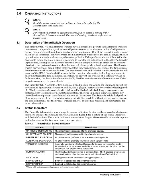
The <strong>SmartSwitch</strong> contains seven long-life, status indicators located on the removable electronics<br />
module to indicate the unit and source status. See Table 2 for a listing of the status indicators<br />
and their definitions. The status indicators are active as long as the removable module is in place<br />
and at least one of the two input sources is energized.<br />
Table 2<br />
<strong>SmartSwitch</strong> Status Indicators<br />
Indicator<br />
Description<br />
ON PREFERRED SOURCE The output load is connected to the preferred source.<br />
ON ALTERNATE SOURCE The output load is connected to the alternate source.<br />
PREFERRED SOURCE OK All phases of the preferred source are within voltage limits.<br />
ALTERNATE SOURCE OK All phases of the alternate source are within voltage limits.<br />
TRANSFER INHIBITED Automatic transfer is inhibited. Reasons for transfer (or retransfer) inhibit<br />
include both sources are not available, sources are not synchronized, or the<br />
output load has exceeded the preset limit.<br />
SUMMARY ALARM<br />
The <strong>SmartSwitch</strong> has detected a fault condition. If both sources are available<br />
and synchronized, then the alarm may indicate a <strong>SmartSwitch</strong> failure.<br />
ON BYPASS<br />
The bypass/transfer switch is in the bypass position.<br />
S1 PREFERRED*<br />
Source 1 is selected as the preferred source.<br />
S2 PREFERRED*<br />
Source 2 is selected as the preferred source.<br />
*These LED indicators are only provided on the rackmount units.<br />
Operating Instructions 11


