
Create successful ePaper yourself
Turn your PDF publications into a flip-book with our unique Google optimized e-Paper software.
<strong>Harken</strong>, Inc. • N15W24983 Bluemound Rd, Pewaukee, WI 53072-4974 • Tel: 262-691-3320 • Fax: 262-701-5780• Email: hoister@hoister.com • Web: www.hoister.com<br />
WARNING! Strictly follow all instructions to avoid an accident, damage to property,<br />
personal injury or death. See www.harken.com/manuals for additional safety information.<br />
WARNING! This product is not to be used for human suspension. Components may fail<br />
causing person to fall, possibly resulting in serious injury or death.<br />
SAVE TIME! READ THE ENTIRE MANUAL BEFORE BEGINNING HOISTER INSTALLATION.<br />
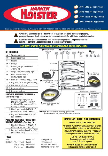
KIT INCLUDES<br />
A 1 Welded screw eye<br />
B 4 Pigtail lag screws<br />
C 1 Shackle<br />
D 4 Pulleys<br />
E 2 Webbing straps with buckles<br />
7' (2.13 m)<br />
F 1 Single black/red hoisting rope<br />
G 1 Block and tackle with<br />
cleat (G1) and rope<br />
H 4 Black drop ropes: 2 long, 2 short<br />
I 4 Lag bolts 1 /4" x 2 1 /2" (6 x 63 mm)<br />
J 4 Washers 1 /4" (6 mm<br />
K 2 Organizer plates<br />
L 2 Organizer pulleys<br />
PURCHASE SEPARATELY IF NEEDED –<br />
See “Note” Step 1b<br />
1 Pine board (riser) (grade 2)<br />
2" x 6" x 7" (50 mm x 152 mm<br />
x 180 mm) Not used for rafters<br />
running sideways<br />
2 Pine boards (grade 2) 2" x 6" x 6'<br />
(50 mm x 152 mm x 1.83 m)<br />
8 Lag bolts and washers 5 /16" x 4"<br />
(8 x 100 mm)<br />
PURCHASE ADDITIONAL FOR RAFTERS<br />
RUNNING SIDEWAYS – See Step 2A<br />
1 Pine board (grade 2) 2" x 4" x 6'<br />
(50 mm x 100 mm x 1.83 m)<br />
2 Lag bolts and washers 5 /16" x 3 1 /2"<br />
(8 mm x 90 mm)<br />
Welded screw eye<br />
HCP1443<br />
7757ASSY<br />
7753ASSY<br />
Webbing straps with buckles<br />
HCP1459.SET<br />
(G1) Cleat<br />
7754ASSY<br />
DO NOT UNTIE<br />
Single black/red hoisting rope<br />
HCP1483<br />
Pigtail lag screws<br />
HCP1444<br />
G Block and tackle*<br />
*NOTE: (G) Block and Tackle varies by system size.<br />
Refer to Hoister part number for specific cleat style.<br />
TOOLS<br />
Drill Plumb line Safety glasses<br />
Drill bits: 5/32" (4 mm) Pencil<br />
Tape measure<br />
7/32" (6 mm)<br />
5/16" (8 mm<br />
Stud finder<br />
Stepladder<br />
Wrench (box end or<br />
ratcheting) 7 /16" (11 mm)<br />
E<br />
F<br />
A<br />
B<br />
C<br />
Shackle<br />
072<br />
229/234A<br />
7806<br />
228A<br />
226A<br />
7803<br />
7802<br />
225A<br />
7801<br />
I<br />
Lag bolts<br />
HFS908<br />
J Washers<br />
HFS913<br />
Pulleys<br />
224A<br />
H Drop black ropes<br />
HCP1447/HCP1448<br />
DO NOT UNTIE<br />
Rope Organizer Components<br />
Organizer plates<br />
H-28375A<br />
Organizer pulleys<br />
H-52010<br />
IMPORTANT SAFETY INFORMATION<br />
• NEVER USE TO LIFT A PERSON.<br />
• DISABLE AUTOMATIC GARAGE DOOR OPENER<br />
when installing, raising, or lowering Hoister.<br />
• READ ENTIRE MANUAL CAREFULLY BEFORE<br />
starting installation. It will save you time.<br />
• DO NOT UNTIE ANY ROPES<br />
<strong>System</strong> comes ready to install.<br />
Leave F, G and H together.<br />
• DO NOT RAISE OR LOWER HOISTER<br />
with anyone standing under object.<br />
L<br />
K<br />
D
INSTALLATION OVERVIEW<br />
STEP 1<br />
DETERMINE HOISTER LOCATION<br />
STEP 2<br />
INSTALL MOUNTING BOARDS<br />
PIGTAIL<br />
LAG SCREW<br />
PIGTAIL<br />
LAG SCREW<br />
STEP 3<br />
STEP 4<br />
STEP 5<br />
STEP 6<br />
INSTALL PIGTAIL LAG SCREWS<br />
INSTALL ROPE ORGANIZER<br />
ASSEMBLE HOISTER SYSTEM<br />
OPERATING HOISTER SYSTEM<br />
GARAGE DOOR<br />
2" x 6" x 6' MOUNTING BOARD<br />
Top<br />
View<br />
2" x 6" x 7" RISER BOARD<br />
ORGANIZER<br />
2" x 6" x 6' MOUNTING BOARD<br />
TOP PLATE<br />
MAINTENANCE & WARRANTY<br />
PIGTAIL<br />
LAG SCREW<br />
PIGTAIL<br />
LAG SCREW<br />
FRONT WALL<br />
RAFTER<br />
Rafters run other way? See steps 1B and 2A.<br />
Long Black<br />
Drop Ropes<br />
(H)<br />
Pulley<br />
(D)<br />
Front<br />
2" x 6" x 6'<br />
Back Mounting Board<br />
2" x 6" x 6'<br />
Mounting Board<br />
Pigtail<br />
Lag Screw<br />
(B)<br />
Rope Organizer on<br />
2" x 6" x 7" Riser Board<br />
Pulleys (L)<br />
Plates (K)<br />
Lag Bolts (I)<br />
Washers (J)<br />
Block and Tackle (G)<br />
Welded<br />
Screw Eye<br />
(A)<br />
Shackle<br />
(C)<br />
Cleat<br />
(G1)<br />
Garage<br />
Door<br />
Webbing Straps (E)<br />
Short Black<br />
Drop Ropes<br />
(H)<br />
Single<br />
Red/Black<br />
Hoisting<br />
Rope<br />
(F)<br />
Front<br />
Wall
STEP 1: DETERMINE HOISTER LOCATION<br />
A. PLAN THE INSTALLATION<br />
Pull car into garage with object on car rack.<br />
STORAGE OPTIONS<br />
Measure height of object. Make sure object can be<br />
stored above or below the open garage door.<br />
Measure length of object. Position Hoister so garage<br />
door can open with object lowered.<br />
OPTION 1. Above Garage Door: Clearance to lift and store<br />
object above open garage door.<br />
Opened<br />
Garage Opened Door<br />
Garage Door<br />
Opened<br />
Garage Opened Door<br />
Garage Door<br />
OPTION 2. Below Garage Door: Use if not enough clearance<br />
for Above Garage Door <strong>Storage</strong> (Option 1). Object has<br />
clearance to lift and store below open garage door.<br />
DIAGRAM 1. Position object above car with clearance to<br />
open garage door. If Hoister is mounted too close to<br />
garage door, there may not be clearance to open door.<br />
Mounted too far forward, object may not balance or<br />
lower onto car.
STEP 1 CONTINUED: DETERMINE HOISTER LOCATION<br />
B. PLAN LOCATION OF MOUNTING BOARDS<br />
Mounting boards are used to position Hoister directly<br />
above object to be lifted.<br />
7806 Hoister (200 lb system) requires mounting boards<br />
to span minimum three rafters.<br />
WARNING! Do not screw into laminated rafters.<br />
They are not intended to accept fasteners. Consult<br />
rafter maker for recommendations. Screwing<br />
into laminated rafters may considerably weaken<br />
system, causing load to fall which may cause<br />
an accident.<br />
Note: Mounting boards may not be necessary for installation<br />
in ceiling with exposed rafters. In ceilings with<br />
exposed rafters, system can be installed on rafters.<br />
Position Hoister directly above object to be lifted. If<br />
installing without mounting boards, go to step 3.<br />
DISTANCE BETWEEN MOUNTING BOARDS<br />
Distance between mounting boards should be 1/3 of<br />
object's length.<br />
Exception: Distance between mounting boards for long<br />
canoes/sea kayaks will be less than 1/3 object’s length.<br />
Calculate distance between mounting boards using<br />
formula or chart below.<br />
_________________ x .33 = _________________<br />
Object length 33% Mounting distance<br />
LOCATE CEILING MOUNTING BOARD POSITION<br />
2<br />
Alternate<br />
position<br />
1<br />
3<br />
Garage<br />
Door<br />
Front<br />
Wall<br />
DIAGRAM 3a. Alternate position for rafters running sideways.<br />
Check to make sure 6’ (1.83 m) boards are long enough.<br />
DIAGRAM 2. Center object under mounting points. Position<br />
mounting boards so lifted object is balanced.<br />
Plan Location of Mounting Boards and Welded Eye Screw<br />
Back Mounting Board<br />
Step 1B<br />
Mounting<br />
Board<br />
Placement<br />
1<br />
3<br />
Ceiling<br />
Front Mounting Board<br />
2<br />
Step 5A<br />
Welded<br />
Eye Screw<br />
Placement<br />
Top Plate<br />
STEP 1B<br />
1) Measurement between<br />
center points on<br />
mounting boards _________<br />
(Calculation above)<br />
Garage<br />
Door<br />
Front<br />
Wall<br />
STEP 5A<br />
2) Measurement from center<br />
of front mounting board<br />
to front wall _________<br />
3) Measurement from front<br />
mounting board to<br />
lowest drop point _________<br />
If measurement 2 is less than<br />
measurement 3, refer to<br />
Step 5A, Diagram 12.<br />
DIAGRAM 3. Distance of mounting boards from front wall is important, as it affects the position of the welded screw eye in Step 5A.
STEP 2: INSTALL MOUNTING BOARDS<br />
A. DRILL CEILING RAFTER ATTACHMENT POINTS<br />
LOCATE CEILING RAFTERS<br />
Mounting boards must attach to ceiling rafters (see<br />
diagram 4 and 4a). On finished ceilings, locate rafters<br />
using stud finder. Follow manufacturer's instructions.<br />
Mark center of ceiling rafters. Drill 7 /32" (5.5 mm) holes.<br />
Alternate Position for Rafters that Run Sideways<br />
Top<br />
View<br />
B. DRILL MOUNTING BOARD<br />
Measure center-to-center distance between rafters.<br />
Mark distance on mounting boards. Mark drill points<br />
in the center of the board. Drill 5 /16" (8 mm) holes<br />
completely through the mounting boards.<br />
C. ATTACH MOUNTING BOARDS TO CEILING<br />
Attach mounting boards using 5 /16" (8 mm) lag bolts<br />
and washers (not included).<br />
Do not over-tighten.<br />
Rafters<br />
Rafter<br />
Center-to-Center<br />
Distance<br />
2" x 6"<br />
Mounting Boards<br />
2" X 4" For Mounting Organizer – No Riser Board Used<br />
Front Wall<br />
DIAGRAM 4A. For Alternate Position attach board for mounting<br />
organizer using 5 /16" (8 mm) 3 1 /2" (90 mm) lag bolts and<br />
washers (not included). See Step 3a to determine distance<br />
between mounting boards.<br />
Rafters<br />
Rafter<br />
Center-to-Center<br />
Distance<br />
Rafter<br />
Center-to-Center<br />
Distance<br />
Rafter<br />
Center-to-Center<br />
Distance<br />
Top<br />
View<br />
Mounting Boards<br />
DIAGRAM 4. Mark center-to-center distance between rafters on mounting boards. Attach mounting boards to rafters.
STEP 3: INSTALL PIGTAIL LAG SCREWS<br />
A. DETERMINE PIGTAIL LAG SCREW (B) LOCATION<br />
DRILL 2 HOLES ON EACH MOUNTING BOARD<br />
PULL VEHICLE INTO GARAGE<br />
Drill Hole<br />
<strong>Point</strong><br />
Pigtail Lag Screw Holes<br />
Object Width<br />
Drill Hole<br />
<strong>Point</strong><br />
MOUNTING BOARD<br />
2"<br />
(50 mm)<br />
Add 2" (50 mm) outside<br />
Drill 7/32" (5.5 mm)<br />
hole at each outside point<br />
2"<br />
(50 mm)<br />
DIAGRAM 6. Add 2" (50 mm) outside each mark. Drill a 7 /32"<br />
(5.5 mm) hole at each drill point on mounting boards<br />
Pull vehicle into garage with object on car rack. Disconnect<br />
automatic garage door.<br />
Alternate Position for Rafters that Run Sideways<br />
Top<br />
View<br />
MARK LOCATION POINTS<br />
Use plumb line to locate four lifting points on mounting<br />
boards above vehicle.<br />
2"<br />
(50 mm) Object Width<br />
CEILING<br />
2"<br />
(50 mm)<br />
Rafters<br />
Mounting Boards<br />
2" x 6"<br />
Pigtail Lag Screw Holes<br />
Plumb Lines<br />
Front View<br />
Plumb Lines<br />
2" X 4" For Mounting Organizer – No Riser Board Used<br />
Front Wall<br />
DIAGRAM 7. If rafters run sideways, drill pigtail lag screw<br />
holes on 2" x 6" as shown.<br />
INSTALL PIGTAIL LAG SCREWS<br />
Mounting Board<br />
Mounting Board Mounting Board Board Mounting Board Mounting Board<br />
Mo<br />
DIAGRAM 5. Mark object width on mounting boards.<br />
Top<br />
Thread<br />
Top<br />
Thread<br />
Top Top<br />
Thread Thread<br />
Top<br />
Thread<br />
Over-<br />
Tightened<br />
Past Top Top<br />
Thread<br />
DIAGRAM 8. Install a Pigtail Lag Screw (B) in each hole.<br />
Threads should just disappear into mounting board.<br />
WARNING! Do not over-tighten Pigtail Lag Screw<br />
past top thread. This can weaken fastener hold<br />
which may considerably weaken system, causing<br />
load to fall which may cause an accident.
STEP 4: INSTALL ROPE ORGANIZER<br />
A. MOUNT RISER BOARD AND DRILL HOLES<br />
IMPORTANT! Use smaller drill bit in this step.<br />
B. ASSEMBLE ROPE ORGANIZER<br />
Organizer<br />
Pulleys<br />
(L)<br />
Organizer<br />
Plates<br />
(K)<br />
FRONT WALL<br />
Washer<br />
(J)<br />
Washer<br />
(J)<br />
Lag Bolt<br />
(I)<br />
DIAGRAM 9<br />
Mount 2" x 6" x 7" riser board on front mounting board centered<br />
between the two Pigtail Lag Screws (B). Drill 5 /32"<br />
(4 mm) holes. Attach riser boards using two 1 /4" (6 mm) Lag<br />
Bolts (l) and Washers (J) (included). Do not over-tighten.<br />
DIAGRAM 9. Hold Rope Organizer Plate (K) on riser board<br />
near the side towards the front wall. Use Plate as template<br />
to mark center holes. Drill two 5 /32" (4 mm) holes.<br />
A. INSTALL WELDED SCREW EYE (A)<br />
PLACEMENT ON FRONT WALL<br />
Ceiling<br />
Lag Bolt<br />
(I)<br />
STEP 5: ASSEMBLE HOISTER SYSTEM<br />
2<br />
DIAGRAM 10. Assemble Rope Organizer using Plate (K)<br />
and Pulleys (L). Fasten to mounting board with<br />
Lag Bolts (I) and Washers (J)<br />
IMPORTANT! Do not over-tighten bolts. This can keep<br />
Rope Organizer Pulleys (L) from turning properly.<br />
ROPE ORGANIZER<br />
PIGTAIL LAG<br />
SCREW<br />
FRONT MOUNTING BOARD<br />
PIGTAIL LAG<br />
SCREW<br />
3<br />
Front<br />
Wall<br />
DIAGRAM 11. Distance 2 must be equal or somewhat greater<br />
than distance 3. See chart below. For a larger view, see<br />
Diagram 3.<br />
MAXIMIZING LOWERING OF OBJECT<br />
You may want to lower object to floor or sawhorses.<br />
If distance 2 is much greater than 3, the amount object<br />
can be lowered will be limited by length of supplied rope.<br />
FRONT WALL<br />
WELDED<br />
SCREW EYE<br />
TOP PLATE<br />
DIAGRAM 12. If distance to front wall is less than distance<br />
needed to lift object, move the Welded Screw Eye (A)<br />
along the front wall until distance 2 is equal to distance 3<br />
(see Diagram 11).<br />
If Distance 2 is Distance 3 will be If Distance 2 is Distance 3 will be<br />
10 10 14 6<br />
11 9 15 5<br />
12 8 16 4<br />
13 7 17 3<br />
When distance 2 is much greater than 3, purchase<br />
longer rope for drop ropes (H) to maximize distance<br />
object can be lowered.
STEP 5 CONTINUED: ASSEMBLE HOISTER SYSTEM<br />
Ceiling<br />
B. ATTACH PULLEYS<br />
Place one Pulley (D) on each Pigtail Lag Screw (B).<br />
Front<br />
Wall<br />
DIAGRAM 13. Avoid installing Welded Screw Eye above tall<br />
shelves. Rope must point down to lock.<br />
INSTALL WELDED SCREW EYE (A) ON FRONT WALL<br />
Use stud finder to locate solid wood of top plate. Drill<br />
7/32" (5.5 mm) hole. Screw Welded Screw Eye (A) into<br />
top plate of front wall (near top of ceiling).<br />
Front View<br />
ATTACH BLOCK AND TACKLE (G)<br />
Attach Block and Tackle system (G) to welded Screw<br />
Eye (A) with Shackle (C). Remove ring from shackle<br />
like a key ring. Put pin through top of Cleat (G1).<br />
Put ring back on to secure Shackle (C).<br />
Block and Tackle Cleat (G1)*<br />
TOP PLATE OF FRONT WALL<br />
STUDS<br />
DIAGRAM 14. Top plate of front wall.<br />
7801<br />
7802<br />
Single Black/Red<br />
Hoisting Rope (F)<br />
DIAGRAM 15. Single black/red<br />
hoisting rope must face<br />
down.<br />
*NOTE: Appearance of Cleat<br />
(G1) varies by system size.<br />
Refer to system part number<br />
for specific Block and Tackle<br />
Cleat.<br />
Shackle (C)<br />
7803<br />
7806
5<br />
9<br />
12<br />
C. INSTALL ROPE<br />
(D)<br />
Long<br />
Drop<br />
Rope<br />
PULLEY<br />
STEP 5 CONTINUED: ASSEMBLE HOISTER SYSTEM<br />
GARAGE DOOR<br />
PULLEY<br />
(D)<br />
Long<br />
Drop<br />
Rope<br />
POSITION WEBBING STRAPS<br />
Place object in position under system. Place Webbing<br />
Straps (E) under object to be lifted. Push buckles<br />
together to lock.<br />
CEILING<br />
Short Drop<br />
Rope<br />
(D)<br />
PULLEY<br />
Short Drop<br />
Rope<br />
PULLEY<br />
(D)<br />
Tie knots below top of object<br />
so load can be lifted to ceiling.<br />
ORGANIZER<br />
BLOCK & TACKLE<br />
OBJECT<br />
FRONT WALL<br />
TOP PLATE<br />
DIAGRAM 16. Put all four Black Drop Ropes through<br />
Organizer.<br />
Put two shorter Black Drop Ropes through Pulleys (D) on<br />
mounting board with Rope Organizer.<br />
Put two longer Black Drop Ropes through Pulleys (D) on<br />
remaining mounting board.<br />
D. ATTACH STRAPS TO ROPE<br />
TIE ROPE TO WEBBING STRAPS<br />
Keep knot as close to Webbing Strap (E) eye as possible.<br />
DIAGRAM 17. Tie knots below top of object so object can be<br />
lifted to ceiling. Adjust strap length in buckle as needed.<br />
E. ADJUSTING LIFTING SYSTEM<br />
ALIGN SCREW EYES<br />
Webbing Strap Eye<br />
1<br />
4<br />
2<br />
7<br />
DIAGRAM 20. Align Pigtail Lag Screws in direction of rope<br />
running through Pulley.<br />
6<br />
3<br />
DIAGRAM 18. Tie a Black Drop Rope to each Webbing Strap<br />
(E) using a figure-eight knot. Pass free end of rope through<br />
the sewn Webbing Strap eye.<br />
Webbing Strap Eye<br />
14<br />
8<br />
LEVEL OBJECT<br />
All webbing straps and ropes must have equal tension<br />
to keep object level. Check by slowly pulling the Black/<br />
Red Hoisting Rope (F).<br />
To level object, adjust tension by moving knot or<br />
adjusting webbing strap at buckle.<br />
11<br />
15<br />
10<br />
13<br />
DIAGRAM 19. Using free end of rope from Webbing Strap<br />
eye, retrace original figure-eight knot in reverse.<br />
Tightly cinch all four strands of rope exiting the knot.<br />
Tighten knots. See www.harken.com/knots for further<br />
knot tying resources.
STEP 6: OPERATING HOISTER SYSTEM<br />
WARNING! Disable garage door opener when<br />
installing, raising, or lowering the Hoister. Do<br />
not raise or lower with anyone standing under<br />
object. Keep area below Hoister clear. If the<br />
load falls it may cause an accident.<br />
B. STORE OBJECT<br />
With object in raised position make sure Single Black/<br />
Red Hoisting Rope (F) is securely locked in cleat with rope<br />
pointed down (see Diagram 21). Coil loose rope end.<br />
A. RAISE OBJECT<br />
Hoist in a series of pulls. Pull Single Black/Red Hoisting<br />
Rope (F) straight down.<br />
WARNING! This product is not to be used for<br />
human suspension. Components may fail<br />
causing person to fall, possibly resulting<br />
in serious injury or death.<br />
WARNING! Hang coiled rope where it will not<br />
accidentally snag on persons or vehicle. Keep<br />
coiled rope out of reach of children. Damage or<br />
injury may result if rope is angled away from wall<br />
with some tension; the object can come down<br />
very quickly which may cause an accident.<br />
Tip: For additional security, use two 5/16" (8 mm)<br />
polyester safety ropes. Securely tie ends to pigtail lag<br />
screws under object, parallel with Webbing Straps (E).<br />
Remove safety ropes before lowering object.<br />
With rope pointed down the cleat will lock the rope<br />
and you can release it. Repeat until object is at<br />
desired height.<br />
C. LOWER OBJECT<br />
Securely grip rope, apply tension and angle it away<br />
from front wall. Bring arm up to let rope out and then<br />
back towards the wall to lock the rope. Repeat until<br />
object is at desired height.<br />
LOCKED:<br />
Rope (F) down<br />
OPEN:<br />
Rope (F) angled<br />
DIAGRAM 21. Locked (left): Single Black/Red Hoisting Rope<br />
(F) pointed straight down locks cleat. Open (right): Angled<br />
rope opens cleat.<br />
WARNING! Stop pulling as soon as object<br />
contacts ceiling or webbing strap knots stop at<br />
pulley (D). Damage or injury may result from<br />
forcing the system. If in doubt, stop hoisting,<br />
allow cleat to lock by angling rope down. Stand<br />
back to see if object is raised to the maximum<br />
or if something is jamming rope or object.<br />
LOWERING:<br />
(Cleat Open)<br />
Tip: Use gloves to protect hands.<br />
LOCKED<br />
WARNING! When operating system, make sure<br />
area below object is clear of persons. If object<br />
comes down too quickly this may cause an<br />
accident.<br />
CAUTION! Avoid injury, do not let rope slip<br />
through hands. Angle rope to wall to lock rope.
MAINTENANCE<br />
MAINTENANCE<br />
Inspect rope (H and F), knots and straps (E) regularly<br />
for signs of chafe, wearing or UV damage. Replace<br />
immediately. Inspect knots for signs of slipping. When<br />
attaching top, inspect webbing strap buckles (E) to<br />
make sure spring clip functions properly. Replace rope<br />
and hardware with <strong>Harken</strong> parts only.<br />
WARRANTY<br />
WARRANTY<br />
What Is Covered – This warranty covers defects in<br />
materials or workmanship.<br />
Who Is Covered – The original purchaser.<br />
For How Long – <strong>Harken</strong> ® products are warranted for<br />
five (5) years from the date of purchase:<br />
After the end of any specific warranty period noted<br />
above, HARKEN ® MAKES NO EXPRESS OR IMPLIED<br />
WARRANTIES OF ANY KIND WITH RESPECT TO<br />
THE PRODUCTS, INCLUDING ANY WARRANTY OF<br />
MERCHANTABILITY OR FITNESS FOR A PARTICULAR<br />
PURPOSE. Some states, or if you live outside the U.S.,<br />
some countries, do not allow limitations on how long<br />
an implied warranty lasts, so the above limitation may<br />
not apply to you.<br />
What Is Not Covered – This warranty does not cover<br />
any product that was: improperly installed; inadequately<br />
inspected after installation; improperly maintained; used<br />
in any application for which it was not intended; used<br />
under load conditions exceeding the rating or other<br />
recommendation published in the <strong>Harken</strong> ® catalog; or<br />
subject to misuse, negligence, accident, or unauthorized<br />
modification or repair. Ropes, buckles and webbing are<br />
also not covered. Labor charges are also not covered.<br />
Separate warranty provisions may be available from<br />
vendors on some of the above products. Contact<br />
<strong>Harken</strong> ® for this warranty information.<br />
CONSEQUENTIAL AND INCIDENTAL DAMAGES<br />
ARE NOT RECOVERABLE UNDER THIS WARRANTY.<br />
Some states do not allow the exclusion or limitation of<br />
incidental damages, so the above limitation or exclusion<br />
may not apply to you.<br />
How To Get Service – If something goes wrong,<br />
contact <strong>Harken</strong> ® directly or your local <strong>Harken</strong> ® dealer<br />
to arrange for warranty assistance. Your dealer has<br />
<strong>Harken</strong> ® Warranty Return Guidelines that provide you<br />
with exact return procedures depending on the product<br />
involved. We will need, in writing, your name, address,<br />
phone number, date of purchase, product involved,<br />
application, an explanation of the defect and conditions<br />
under which the product was used. We are fair and we<br />
do care when <strong>Harken</strong> ® products do not perform.
CEILING LEVEL STORAGE<br />
Each Hoister kit is complete and simple to install.<br />
Easy one-person operation with a single control rope.<br />
Self-locking cleat grips instantly if accidentally released.<br />
Do not use this product for human suspension.<br />
SELECT THE HARKEN HOISTER YOU NEED:<br />
1. Determine maximum<br />
weight you will lift and<br />
select correct Hoister.<br />
Lifting Weight<br />
Part <strong>Storage</strong> Mechanical Min Max<br />
No. <strong>System</strong> (lb) advantage lb kg lb kg<br />
7801 60 3:1 15 7 60 27<br />
7802 90 4:1 25 11 90 41<br />
7803 145 6:1 45 20 145 66<br />
7806 200 8:1 75 34 200 91<br />
2. Standard Hoisters are designed for a maximum ceiling height of 10 ft (3 m). Contact <strong>Harken</strong> for taller ceilings that require a<br />
lift greater than 10 ft (3 m).<br />
3. Check distance between ceiling and top of garage door in open position. Will object fit in this space? If not, will object lift and<br />
store under garage door in open position? If not, consider turning the object 90° and placing in the front of garage.<br />
4. Hoisters 7801, 7802, 7803, and 7806 are designed to lift an object no wider than 5 ft (1.52 m). Width can increase if vertical lift is<br />
lower or a taller ceiling model is used.<br />
Tools: Drill, Drill Bits: 5 /32 in (4 mm), 7 /32 in (6 mm), 5 /16 in (8 mm), Plumb Line, Pencil, Stud Finder, Stepladder, Safety Glasses, Tape<br />
Measure, Wrench: 7 /16 in (11 mm) Box End or Ratcheting.<br />
Optional Supplies<br />
Qty Description Size Length<br />
2 Pine Boards (Grade 2) 2 x 6 (50 mm x 152 mm) 6 ft (1.83 m)<br />
1 Pine Boards (Grade 2) 2 x 6 (50 mm x 152 mm) 7 in (180 mm)<br />
8 Lag Bolts/Washers 5 /16 in (8 mm) 4 in (100 mm)<br />
Rafters Running Sideways (Purchase Above Plus Following)<br />
1 Pine Boards (Grade 2) 2 x 4 (50 mm x 100 mm) 6 ft (1.83 m)<br />
2 Lag Bolts/Washers 5 /16 in (8 mm) 3 1 /2 in ( 90 mm)<br />
<strong>Harken</strong>, Inc. • N15W24983 Bluemound Rd, Pewaukee, WI 53072-4974 • Tel: 262-691-3320<br />
Fax: 262-701-5780 • Email: hoister@hoister.com • Web: www.hoister.com<br />
4907 11/13 Printed in USA