
You also want an ePaper? Increase the reach of your titles
YUMPU automatically turns print PDFs into web optimized ePapers that Google loves.
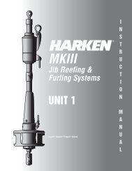
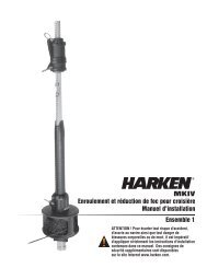
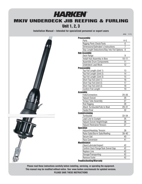
MKIV UNDERDECK JIB REEFING & FURLING<br />
<strong>Unit</strong> 1, 2, 3<br />
Installation Manual – Intended for specialized personnel or expert users<br />
Please read these instructions carefully before installing, servicing, or operating the equipment.<br />
This manual may be modified without notice. See: www.harken.com/manuals for updated versions.<br />
PLEASE SAVE THESE INSTRUCTIONS<br />
4656 11/13<br />
Preassembly<br />
Parts 4–5<br />
Rigging Parts Check/Tools 6<br />
Dimensions/Sailmaker's Instructions 7<br />
Stay Length Deductions/Stay Into Foil Options 8<br />
Hub Assembly<br />
Deck Flange 9<br />
Install Hub Assembly in Bow 10–11<br />
Assemble Drum Components 11<br />
Underdeck Lead Block 12<br />
Preassembly<br />
Top Foil Length (<strong>Unit</strong> 1) 13<br />
Top Foil Length (<strong>Unit</strong> 2) 14<br />
Top Foil Length (<strong>Unit</strong> 3) 15<br />
Short Top Foil (<strong>Unit</strong> 1) 16<br />
Short Top Foil (<strong>Unit</strong> 2) 17<br />
Short Top Foil (<strong>Unit</strong> 3) 18<br />
Confirm Foil Length 19<br />
Assembly<br />
Foils/Connectors 20–26<br />
Halyard Swivel 26<br />
Torque Tube Assembly 27<br />
Rod Rigging 28<br />
Attach Turnbuckle/Foils to Boat 29–31<br />
Feeder/Final 32<br />
Commissioning<br />
Turnbuckle 33–34<br />
Lead Line to Cockpit 35<br />
Halyard Swivel Height/Angle 36<br />
Halyard Restrainer/Tension 37<br />
Operation<br />
Halyard/Headstay Tension 38<br />
Raise Sails/Storm Sails/Reefing 39–40<br />
Secure Sail 40<br />
Race Conversion 41<br />
Maintenance<br />
Clean/Lubricate/Inspect 42<br />
Confirm Deck Flange/Tack Swivel Gap 42<br />
Replace Line 42<br />
Storage/Transporting 42<br />
Remove Furler 42<br />
Troubleshooting/Warranty
Parts Description<br />
Introduction<br />
This manual gives technical information on installation and service. This information is destined exclusively for<br />
specialized personnel or expert users. Installation, disassembling, and reassembling by personnel who are not<br />
experts may cause serious damage to property or injury to users and those in the vicinity of the product. If you<br />
do not understand an instruction contact <strong>Harken</strong>.<br />
The user must have appropriate training in order to use this product.<br />
<strong>Harken</strong> accepts no responsibility for damage or harm caused by not observing the safety requirements and<br />
instructions in this manual. See limited warranty, general warnings, and instructions in www.harken.com/manuals.<br />
Purpose<br />
<strong>Harken</strong> ® Jib Reefing and Furling is designed for rolling sails on sailboats to reduce sail size or to completely roll<br />
so wind has little effect on the sail. Use of this product for other than normal sailboat applications is not covered<br />
by the limited warranty.<br />
Safety Precautions<br />
WARNING! This symbol alerts you to potential hazards that may kill or hurt you and others<br />
if you don't follow instructions. The message will tell you how to reduce the<br />
chance of injury.<br />
18<br />
CAUTION! This symbol alerts you to potential hazards that may hurt you and others if<br />
you do not follow instructions. The message will tell you how to reduce the<br />
chance of injury.<br />
19<br />
WARNING! Strictly follow all instructions to avoid potential<br />
hazards that may kill or hurt you and others. See www.harken.com/<br />
manuals, for general warnings and instructions.<br />
15<br />
16<br />
17<br />
1<br />
6<br />
2<br />
Parts Descriptions<br />
5<br />
3<br />
1) Lower Jaw/Jaw Toggle<br />
2) Threaded Stud<br />
3) Length Adjuster Nut<br />
4) Hub Assembly<br />
7<br />
4<br />
8 9<br />
11<br />
13<br />
12<br />
10<br />
5) Flange Assembly<br />
6) Guard Assembly<br />
7) Cover Assembly<br />
8) Deck Flange<br />
14<br />
2. <strong>Harken</strong> does not recommend drilling boat’s chainplate or toggle.<br />
Bushings may be available to fit boats with smaller clevis pin sizes.<br />
Part No. Size Wire Size Rod Size Clevis Pin Ø<br />
7411.11 1 /2 <strong>Unit</strong> 1 1 /4", 9 /32", 5 /16" -8, -10<br />
½"<br />
6 mm, 7 mm, 8 mm 5.72 mm 6.35 mm 12.7 mm<br />
7412.11 5 /8 <strong>Unit</strong> 2 5 /16", 3 /8" -12, -17<br />
5 /8"<br />
8 mm, 10 mm 14 mm, 8.38 mm 15.9 mm<br />
7413.11 3 /4 <strong>Unit</strong> 3 7 /16", 1 /2" -22, -30<br />
3 /4"<br />
11 mm, 12 mm 9.53 mm, 11.1 mm 19.1 mm<br />
7413.11 7 /8 <strong>Unit</strong> 3 7 /16", 1 /2" -22, -30<br />
7 /8"<br />
11 mm, 12 mm 9.53 mm, 11.1 mm 22.2 mm<br />
2 MKIV Underdeck <strong>Unit</strong> 1, 2, 3<br />
WARNING! Do not drill boat's chainplate or toggle.<br />
This may result in rig failure. Use the correct<br />
size toggle and clevis pin.<br />
9) Tack Swivel<br />
10) Tack Shackle<br />
11) Bearing Caps<br />
12) Upper Jaw/Jaw Toggle<br />
Size Check<br />
1. Check headstay and clevis pin<br />
dimensions in chart below.<br />
Standard<br />
Headstay Length<br />
45' 11"<br />
13.99 m<br />
60' 4"<br />
18.38 m<br />
75' 1"<br />
22.88 m<br />
75' 1"<br />
22.88 m<br />
Max.<br />
Headstay Length<br />
52' 11"<br />
16.12 m<br />
67' 4"<br />
20.51 m<br />
82' 1"<br />
25.02 m<br />
82' 1"<br />
25.02 m<br />
13) Torque Tube Universal<br />
14) Torque Tube Assembly<br />
15) Foil Clamp<br />
16) Bottom Foil
Preassembly<br />
Sizing Check<br />
25<br />
24<br />
26<br />
22<br />
21<br />
23<br />
19<br />
20<br />
E<br />
A<br />
B<br />
D<br />
F<br />
C<br />
Will Drum Fit in Bow?<br />
Note: If length of stud does not allow attachment to chainplate, link plates<br />
between chainplate and toggle must be fabricated.<br />
G<br />
H<br />
Furler Requires Drained Compartment<br />
<strong>Harken</strong>’s Underdeck Furler is designed to keep much of the water from<br />
entering the bow compartment. Water will drip through the furler during<br />
rain or when sailing in heavy weather. Furling compartment must drain.<br />
J<br />
I<br />
<strong>Unit</strong> Part No. A B C D Max E F G Min G Max H Min H Max I J<br />
1<br />
7411.11 1 /2 5 1 /2" 4 9 /16" 4 11 /16" 1 1 /2" 3 11 /16" 2 5 /16" 4 5 /8" 9 5 /8" 10 5 /8" 15 5 /8" /2" 4 1 /8"<br />
140 mm 116 mm 119 mm 38 mm 94 mm 58 mm 117 mm 244 mm 270 mm 397 mm 12.7 mm 105 mm<br />
2<br />
7412.11 5 /8 6 5 /8" 5 1 /16" 5 1 /4" 1 13 /16" 4 3 /16" 2 3 /4" 5 3 /8" 11 5 /16" 12 11 /16" 18 9 /16" /8" 5"<br />
167 mm 129 mm 134 mm 46 mm 106.5 mm 70 mm 137 mm 287 mm 322 mm 471 mm 15.9 mm 127 mm<br />
3<br />
7413.11 3 /4 8 3 /16" 6 1 /2" 6 3 /4" 2 1 /2" 5 7 /16" 3 5 /8" 6 7 /8" 14 3 /8" 16 1 /8" 23 5 /8" /4" 6 5 /16"<br />
208 mm 166 mm 172 mm 64 mm 138.5 mm 92 mm 175 mm 365 mm 410 mm 600 mm 19.1 mm 160 mm<br />
3<br />
7413.11 7 /8 8 3 /16" 6 1 /2" 6 3 /4" 2 1 /2" 5 7 /16" 3 5 /8" 7 5 /16" 15" 16 9 /16" 24 1 /4" /8" 6 5 /16"<br />
208 mm 166 mm 172 mm 64 mm 138.5 mm 92 mm 186 mm 381 mm 421 mm 616 mm 22.2 m 160 mm<br />
17) Feeder<br />
18) Connector Bushing<br />
19) Bottom Connector<br />
20) 7' (2.13 m) Foil<br />
21) Connector Screws<br />
22) Connector Wedge<br />
23) Connector<br />
24) Halyard Swivel<br />
25) Trim Cap Screws<br />
26) Trim Cap<br />
MKIV Underdeck <strong>Unit</strong> 1, 2, 3 3
Preassembly<br />
Parts<br />
7' (2.13 m)<br />
Foils<br />
2' (610 mm)<br />
Bottom Foil<br />
Halyard Swivel<br />
Cover Assembly<br />
Flange Assembly<br />
Guard Assembly<br />
Torque Tube<br />
Assembly<br />
Main Components<br />
Hub Assembly<br />
Part No.<br />
Description <strong>Unit</strong> 1 <strong>Unit</strong> 2 <strong>Unit</strong> 3-3/4 <strong>Unit</strong> 3-7/8 Qty<br />
Halyard swivel H-39812 H-39794 H-39392 H-39392 1<br />
Torque Tube Assembly HFG927 HFG928 HFG929 HFG929 1<br />
Hub Assembly HFG923 HFG924 HFG925 HFG926 1<br />
Cover Assembly HFG683 HFG686 HFG689 HFG689 Pair<br />
Flange Assembly HFG684 HFG687 HFG690 HFG690 Pair<br />
Guard Assembly HFG685 HFG688 HFG691 HFG691 Pair<br />
Line (Not included with Furler)<br />
Note: Line is not included with furler. Drum of<br />
unit is smaller to allow it to fit into narrow bow<br />
sections. If overlapping sails are used, standard<br />
diameter line will fill up drum and jam furler. To<br />
prevent this, use small diameter, high strength<br />
line at forward end and have a rigger add a<br />
cover at aft end where line is handled.<br />
Line Specifications<br />
<strong>Unit</strong><br />
Forward Ø<br />
Min Break<br />
Strength<br />
Aft Ø<br />
1 1 /4" (6 mm) 2500 lb (1130 kg) 5 /16" (8 mm)<br />
2 5 /16" (8 mm) 3740 lb (1700 kg) 3 /8" (10 mm)<br />
3 3 /8" (10 mm) 5000 lb (2270 kg) 7 /16" (12 mm)<br />
Foils (Standard Package)<br />
Description <strong>Unit</strong> Part No. Qty<br />
7' (2.13 m) Foil<br />
7411.30 6<br />
1<br />
2' (610 mm) Bottom foil 7411.33 1<br />
7' (2.13 m) Foil<br />
7412.30 8<br />
2<br />
2' (610 mm) Bottom foil 7412.33 1<br />
7' (2.13 m) Foil<br />
7413.30 10<br />
3<br />
2' (610 mm) Bottom foil 7413.33 1<br />
4 MKIV Underdeck <strong>Unit</strong> 1, 2, 3
Preassembly<br />
Parts<br />
Connector Bushings<br />
Trim Cap Screws<br />
Plastic<br />
Connector<br />
Wedges<br />
Bow Shackles<br />
Foil Screws<br />
Trim Cap<br />
Bottom<br />
Connector<br />
Connectors<br />
Prefeeder<br />
Hex Keys<br />
Feeder<br />
Hex Keys (Supplied)<br />
Description <strong>Unit</strong> Qty<br />
2.5, 4, 5 mm 1 1 Each<br />
3, 4, 5, 6 mm 2 1 Each<br />
3, 4, 6, 10 mm 3 1 Each<br />
Other Components<br />
Blue Loctite ®<br />
Red Loctite ®<br />
Injector<br />
5200<br />
Adhesive<br />
<strong>Unit</strong> 1 <strong>Unit</strong> 2 <strong>Unit</strong> 3 (3/4, 7/8)<br />
Description Part No. Qty Size Part No. Qty Size Part No. Qty Size<br />
Connector 7411.31 5 7" (177.8 mm) 7412.31 7 9" (229 mm) 7413.31 9 9.75"(248 mm)<br />
Bottom connector 7411.32 1 10.75" (273 mm) 7412.32 1 13" (330 mm) 7413.32 1 14" (356 mm)<br />
Bow shackle 2110 3 6 mm 2117 3 8 mm 2124 3 10 mm<br />
Connector bushing set<br />
Plastic connector wedge set<br />
Foil screw set<br />
Trim cap set<br />
Trim cap screw set<br />
<strong>Unit</strong> 1 <strong>Unit</strong> 2 <strong>Unit</strong> 3 (3/4, 7/8)<br />
Description Part No. Qty Part No. Qty Part No. Qty<br />
HFG295<br />
(12-H-42062/12-H-42063)<br />
HFG299<br />
(14-H-39625)<br />
HFG343<br />
(28-HFS1105)<br />
HFG680<br />
(H-37361/H-37362)<br />
HFG629<br />
(3-HFS1126)<br />
1<br />
1<br />
1<br />
1<br />
1<br />
HFG296<br />
(16-H-42032/16-H-42033)<br />
HFG300<br />
(18-H-39487)<br />
HFG348<br />
(36-HFS1106)<br />
HFG681<br />
(H-37403/H-37404)<br />
HFG672<br />
(3-HFS1127)<br />
1<br />
1<br />
1<br />
1<br />
1<br />
HFG297<br />
(20-H-42073/20-H-42074)<br />
HFG324<br />
(22-H-39487)<br />
HFG349<br />
(44-HFS1106)<br />
HFG682<br />
(H-39751/H-39752)<br />
HFG672<br />
(3-HFS1127)<br />
Prefeeder 947 1 947 1 947 1<br />
Feeder with screw and tab H-39683 1 H-39559 1 H-39756 1<br />
Injector, 1 oz. 5200 Adhesive HFG725 1 HFG725 1 HFG725 1<br />
Loctite ® Blue 833 1 833 1 833 1<br />
Loctite ® Red HFG739 2 HFG739 2 HFG739 2<br />
1<br />
1<br />
1<br />
1<br />
1<br />
MKIV Underdeck <strong>Unit</strong> 1, 2, 3 5
Preassembly<br />
1. Stud/eye turnbuckle components are not included and<br />
must be purchased separately. See page 8.<br />
2. Rod rigging requires <strong>Harken</strong> rod adapter stud.<br />
3. Order <strong>Harken</strong> Lead Blocks and one additional<br />
7403 if necessary. Fits 1" (25 mm) stanchions.<br />
<strong>Unit</strong> 1, 2<br />
7404 Lead Block Kit<br />
(Sold Separately)<br />
ROD RIGGING<br />
<strong>Harken</strong> Rod Adapter<br />
Stud Required<br />
(Sold Separately)<br />
Adhesive Alert<br />
Rigging Parts Check/Tools<br />
MKIV Furlers are shipped with 3M 5200<br />
adhesive. Use adhesives on dry connectors<br />
and foils using the special injection system<br />
described in the assembly section. Parts<br />
may immediately be exposed to rain. Cure<br />
is best at 70F (22C) with 50% humidity. Do<br />
not apply at temperatures below 40F (5C)<br />
and above 100F (38C).<br />
131, 047<br />
349, 2652<br />
Recommended Furling<br />
Compartment Lead Blocks<br />
<strong>Unit</strong> Turning Thru-Deck<br />
1 349 131<br />
2 2652 047<br />
3 2600/137/071 HC7981<br />
Rod Adapter Stud<br />
<strong>Unit</strong> Part No. Thread Ø<br />
1<br />
7422 -8 1 /2" - 20RH<br />
7423 -10 1/2" - 20RH<br />
2<br />
7424 -12 5 /8" - 18RH<br />
7425 -17 5 /8" - 18RH<br />
3<br />
7426 -22 3 /4" - 16RH<br />
7427 -30 7 /8" - 14RH<br />
Although adhesive has not cured it will<br />
remain in place on foil joints whether<br />
they are left on the ground or raised up<br />
on boat. Foils can be raised immediately<br />
after assembly and sails fitted.<br />
Note: A small amount of adhesive may<br />
bulge out of injection ports. If possible<br />
let system sit for a couple days before<br />
sailing. If adhesive gets on sails remove<br />
using acetone. For faster-curing adhesive,<br />
purchase 4200 Fast Cure.<br />
Tools You Will Need<br />
Note: Damaged foils can be repaired.<br />
Use a hand-held propane torch to heat<br />
joints until foils can be pulled apart.<br />
1<br />
2<br />
3<br />
8<br />
4<br />
12<br />
5<br />
<strong>Unit</strong><br />
Drill Ø<br />
1 1 /8" (3 mm), 1 /4" (6.25 mm)<br />
2 5 /32" (4 mm), 1 /4" (6.25 mm)<br />
3 ( 3 /4, 7 /8) 5 /32" (4 mm), 1 /4" (6.25 mm) 15<br />
16<br />
18<br />
Deck<br />
<strong>Unit</strong> Flange Ø<br />
1 3.7"<br />
(94 mm)<br />
2 4.2"<br />
(106.5 mm)<br />
3 5.45"<br />
(138.5 mm)<br />
Hole<br />
Saw Size<br />
3 ¾"<br />
(95 mm)<br />
4 ¼"<br />
(110 mm)<br />
5 ½"<br />
(140 mm)<br />
Wrench Size<br />
<strong>Unit</strong> for Length Adjuster<br />
1 7 /8"<br />
(22 mm)<br />
2 1"<br />
(25 mm)<br />
3 1.25"<br />
(32 mm)<br />
19<br />
6<br />
10<br />
Use 6 mm bolts and washers to<br />
13<br />
mount deck flange. To figure bolt<br />
length, add 3 /8" (10 mm) to deck<br />
thickness. Minimum thread<br />
7<br />
9<br />
11<br />
14<br />
17 engagement must be 9mm.<br />
1. Long tape measure 6. Side cutters 11. Center punch 16. Hole saw<br />
2. Short tape measure 7. Rat-tail file 12. Rigging or black tape 17. Deck sealant<br />
3. Power drill 8. Hex Keys (provided) 13. Scissors 18. Box end wrench<br />
4. Drill bits (see chart) 9. Slotted/phillips screwdrivers 14. Metal straight edge 19. 6 mm bolts, nuts and washers<br />
5. Hacksaw 10. Needle-nose pliers 15. Hammer<br />
6 MKIV Underdeck <strong>Unit</strong> 1, 2, 3
Preassembly<br />
Dimensions/Sailmaker's Instructions<br />
A<br />
B<br />
Luff Length<br />
Note offsets above and below sail.<br />
A shorter luff may be required if a halyard restrainer is necessary<br />
(page 37) or a toggle or long toggle assembly is used to raise drum.<br />
If luff of sail is not long enough to put halyard swivel near top of<br />
headstay foil, a pendant must be added. See page 36.<br />
Tack Setback<br />
Find setback "C" for tack shackle in chart below and modify sail<br />
accordingly. Setback is measured to luff tape of sail.<br />
Luff Tape Size<br />
All units require #6 ( 6 /32" or 5 mm) luff tape.<br />
C<br />
F<br />
Luff Tape Length<br />
Cut off top of luff tape so it is 18 to 24" (450 to 600 mm) below<br />
head of sail. This allows head to lag behind rest of sail to help<br />
flatten sail. It will also help head to roll more smoothly.<br />
Note feeder height and extend bottom of luff tape downward so<br />
it is below feeder. This will prevent luff tape from catching in<br />
feeder as sail is lowered.<br />
Tack and Head Shackles<br />
Make sure tack and head shackles fit sail<br />
rings. The minimum inside dimensions<br />
of standard head and tack shackles are:<br />
A<br />
<strong>Unit</strong> A B<br />
1 1 1 /16" (27 mm) 1 /2" (13 mm)<br />
2 1 3 /4" (44 mm) 11 /16" (17 mm)<br />
3 1 7 /8" (48 mm) 13 /16" (21 mm)<br />
B<br />
E<br />
Suncover<br />
Suncovers may be installed on either side of sail. Be<br />
sure to match other sails in the customer's inventory.<br />
D<br />
G<br />
<strong>Unit</strong> Part No. A B C D E F G<br />
1 7411.11 1 /2<br />
2 7412.11 5 /8<br />
3 7413.11 3 /4<br />
3 7413.11 7 /8<br />
4 3 /4"<br />
120 mm<br />
5 5 /8"<br />
143 mm<br />
7 5 /16"<br />
186 mm<br />
7 5 /16"<br />
186 mm<br />
7"<br />
177 mm<br />
9 1 /8"<br />
231 mm<br />
11 5 /8"<br />
296 mm<br />
11 5 /8"<br />
296 mm<br />
1 15 /16"<br />
49 mm<br />
2 5 /16"<br />
59 mm<br />
3 3 /16"<br />
81 mm<br />
3 3 /16"<br />
81 mm<br />
1 /16"<br />
2 mm<br />
1 /16"<br />
2 mm<br />
1 /16"<br />
2 mm<br />
1 /16"<br />
2 mm<br />
—<br />
9 /16"<br />
14mm<br />
7 /16"<br />
11mm<br />
—<br />
37 13 /16"<br />
960 mm<br />
41 1 /16"<br />
1043 mm<br />
47 3 /16"<br />
1199 mm<br />
46 1 /16"<br />
1170 mm<br />
3 5 /8"<br />
92 mm<br />
4 1 /16"<br />
104 mm<br />
5 3 /8"<br />
136 mm<br />
5 13 /16"<br />
148 mm<br />
MKIV Underdeck <strong>Unit</strong> 1, 2, 3 7
Preassembly<br />
Deduction for Stay Length/Stay Into Foil Options<br />
Use dimensions of <strong>Harken</strong> toggle below to build stay to correct length.<br />
Tip: Turnbuckles should be 1/2 to 2/3rds open to allow shortening for new wire stretch and for fine-tuning mast rake.<br />
A<br />
B<br />
C<br />
D<br />
1. Swage stud at end of wire.<br />
2. Open end of wire and install Norseman or Sta-Lok ® stud after<br />
foil is assembled.<br />
3. Rod adapter nosepiece for <strong>Harken</strong> rod adapter stud: Threaded<br />
nosepiece must have a positive lock as well as adhesive.<br />
Use <strong>Harken</strong> stud with cotter pins. See page 28.<br />
<strong>Unit</strong> Part No. A B C D<br />
1 7411.11 1 /2 1 /16"<br />
2 mm<br />
3 5 /8"<br />
92 mm<br />
10 5 /8"<br />
270 mm<br />
15 5 /8"<br />
397 mm<br />
2 7412.11 5 /8 1 /16"<br />
2 mm<br />
4 1 /8"<br />
104 mm<br />
12 11 /16"<br />
322 mm<br />
18 9 /16"<br />
471 mm<br />
3 7413.11 3 /4 1 /16"<br />
2 mm<br />
5 3 /8"<br />
136 mm<br />
16 1 /8"<br />
410 mm<br />
23 5 /8"<br />
600 mm<br />
3 7413.11 7 /8 1 /16"<br />
2 mm<br />
5 13 /16"<br />
148 mm<br />
16 9 /16"<br />
421 mm<br />
24 1 /4"<br />
616 mm<br />
Options for Snaking Stay into Foils<br />
WARNING! Using a threaded nosepiece with only<br />
adhesive at the upper rod eye terminal may result<br />
in headstay system failure. Make sure there is a<br />
mechanical lock.<br />
8 MKIV Underdeck <strong>Unit</strong> 1, 2, 3
Assembly<br />
Deck Flange<br />
72 1 /2° – 74 1 /2°<br />
Note: Deck flange angle<br />
matches a stay angle of<br />
731/2° when compared<br />
to deck. Angles can vary<br />
between 721/2° and 741/2°.<br />
Carefully locate center point in deck to<br />
locate deck flange. Line from mast to<br />
under deck chainplate must intersect this<br />
center point. Mark center fore/aft and<br />
athwartships line. Use template to mark<br />
four outer holes and center pilot hole.<br />
Make sure closer pair of holes is forward.<br />
If deck does not fall within these angles,<br />
shims must be made using structural<br />
adhesive to avoid excessive pressure<br />
on deck and deck bearings.<br />
Once you are certain hole is located in<br />
line with chainplate and any required<br />
shimming is done, drill hole 90° to deck.<br />
Make sure hole is just large enough so deck<br />
flange bears against deck. It is better to<br />
make hole slightly smaller and file opening<br />
larger to fit. Use template to mark large hole<br />
and bolt holes. Use hole saw to drill deck.<br />
Tip: After pilot drill bit clears deck, drill final<br />
hole from bottom using pilot hole to line up<br />
hole drilled from top. This will prevent glass<br />
from chipping.<br />
Use 6 mm screws and compound to fasten<br />
deck flange.<br />
Note: There must be a minimum of 3/8"<br />
(9 mm) thread engagement into deck flange.<br />
MKIV Underdeck <strong>Unit</strong> 1, 2, 3 9
Assembly<br />
Install Hub Assembly in Bow<br />
Slide hub assembly into deck<br />
flange. Turn adjusting nut to<br />
lengthen or shorten threaded<br />
stud as needed.<br />
Adjust length so toggle is lined up with chainplate hole. Slide pin<br />
into chainplate and secure with cotter pin.<br />
Stud Length<br />
Shorten<br />
Lengthen<br />
Turn Adjusting Nut<br />
Clockwise<br />
Counter-Clockwise<br />
1 /16"– 1 /8"<br />
2–4 mm<br />
Distance between bottom of<br />
tack swivel and deck flange<br />
must be 1 /16"– 1 /8" (2–4 mm).<br />
10 MKIV Underdeck <strong>Unit</strong> 1, 2, 3<br />
From on-deck, pull up on unit to check height between deck flange and<br />
tack swivel. Make sure tack swivel is free to rotate when there is upward<br />
pressure on unit. Check this again when stay is up and tensioned.
Assembly<br />
Assemble Drum Components<br />
Place halves of plastic flange in<br />
lower groove on hub assembly<br />
so smooth side of flange is up.<br />
Tip: Line up flats in flange with<br />
flats in groove.<br />
Use blue Loctite ® on flathead<br />
screws (provided).<br />
Tighten screws using hex key<br />
(provided).<br />
Place halves of plastic cover in<br />
grooves so flats in cover align<br />
with flats in groove.<br />
Tip: Rotate each screw hole<br />
towards the stern.<br />
Use blue Loctite ® on flathead<br />
screws (provided).<br />
Tighten screws using hex key<br />
(provided).<br />
Assemble line guard so enclosed<br />
opening faces lead block. Do not<br />
use Loctite ® on threads.<br />
Tip: Loosely thread both screws<br />
turning guard so it can be rotated<br />
to its final position. Finish<br />
tightening final screw when<br />
enclosed opening faces lead<br />
block.<br />
MKIV Underdeck <strong>Unit</strong> 1, 2, 3 11
Assembly<br />
Underdeck Lead Block<br />
Mount lead block so that line exits furler<br />
at 90° to line of headstay as shown.<br />
Remember block will split angle and raise<br />
up slightly under load. Mount thru-deck<br />
block. You may want to angle it toward<br />
stanchion block.<br />
90°<br />
Mount thru-deck block. You may want to<br />
angle it toward stanchion lead block.<br />
12 MKIV Underdeck <strong>Unit</strong> 1, 2, 3
Preassembly<br />
<strong>Unit</strong> 1—Top Foil Length<br />
Measure A and add to this chart<br />
and length chart below<br />
Inches<br />
mm<br />
A<br />
B .50 13<br />
E 24 610<br />
F 15.25 387<br />
Total A+B+E+F<br />
Make sure upper<br />
measurement points<br />
of A and pin-to-pin<br />
are the same.<br />
Alternate<br />
Measurement<br />
Point<br />
TOP FOIL LENGTH WORKSHEET<br />
1 Pin-to-Pin Length<br />
A<br />
Pin<br />
to<br />
Pin<br />
A<br />
B<br />
C<br />
2 Subtract ABEF –<br />
3 Result (Pin-to-Pin – ABEF)<br />
UNIT 1<br />
4 Subtract D –<br />
To find “D” pick number from chart below that is closest<br />
to, but not greater than total from step 3.<br />
Inches<br />
mm<br />
3 x 84 = 252<br />
4 x 84 = 336<br />
5 x 84 = 420<br />
6 x 84 = 504<br />
7 x 84 = 588<br />
8 x 84 = 672<br />
3 x 2133.6 = 6400.8<br />
4 x 2133.6 = 8534.4<br />
5 x 2133.6 = 10668<br />
6 x 2133.6 = 12801.6<br />
7 x 2133.6 = 14935.2<br />
8 x 2133.6 = 17068.8<br />
Example–If result from Step 3 is:<br />
500 inches “D” = 420 inches 12,000 mm<br />
“D” = 10,668 mm<br />
5 Result (C) Top Foil Length<br />
D<br />
E<br />
Pin<br />
to<br />
Pin<br />
Length Check<br />
After completing worksheet above fill in A, C and D below. Add “A”<br />
through “F” to confirm total equals your pin-to-pin measurement.<br />
F<br />
Length Chart<br />
Dimensions Inches mm<br />
A Center of Pin to Bottom of Terminal<br />
B Bottom of Terminal to Top of Foil .50 13<br />
C Top Foil Length<br />
D Number of Foils ________ x 84" (2133.6 mm)<br />
E Bottom Foil 24 610<br />
F Bottom of Foil to Jaw/Jaw Toggle 15.25 387<br />
Pin-to-Pin Length<br />
MKIV Underdeck <strong>Unit</strong> 1 13
Preassembly<br />
<strong>Unit</strong> 2—Top Foil Length<br />
Measure A and add to this chart<br />
and length chart below<br />
Inches<br />
mm<br />
A<br />
B .63 16<br />
E 24 610<br />
F 18.45 469<br />
Total A+B+E+F<br />
Make sure upper<br />
measurement points<br />
of A and pin-to-pin<br />
are the same.<br />
Alternate<br />
Measurement<br />
Point<br />
TOP FOIL LENGTH WORKSHEET<br />
1 Pin-to-Pin Length<br />
A<br />
Pin<br />
to<br />
Pin<br />
A<br />
B<br />
C<br />
2 Subtract ABEF –<br />
3 Result (Pin-to-Pin – ABEF)<br />
UNIT 2<br />
4 Subtract D –<br />
To find “D” pick number from chart below that is closest<br />
to, but not greater than total from step 3.<br />
Inches<br />
mm<br />
5 x 84 = 420<br />
6 x 84 = 504<br />
7 x 84 = 588<br />
8 x 84 = 672<br />
9 x 84 = 756<br />
5 x 2133.6 = 10668<br />
6 x 2133.6 = 12801.6<br />
7 x 2133.6 = 14935.2<br />
8 x 2133.6 = 17068.8<br />
9 x 2133.6 = 19202.4<br />
Example–If result from Step 3 is:<br />
500 inches “D” = 420 inches 12,000 mm<br />
“D” = 10,668 mm<br />
5 Result (C) Top Foil Length<br />
D<br />
E<br />
Pin<br />
to<br />
Pin<br />
Length Check<br />
After completing worksheet above fill in A, C and D below. Add “A”<br />
through “F” to confirm total equals your pin-to-pin measurement.<br />
F<br />
Length Chart<br />
Dimensions Inches mm<br />
A Center of Pin to Bottom of Terminal<br />
B Bottom of Terminal to Top of Foil .63 16<br />
C Top Foil Length<br />
D Number of Foils ________ x 84" (2133.6 mm)<br />
E Bottom Foil 24 610<br />
F Bottom of Foil to Jaw/Jaw Toggle 18.45 469<br />
Pin-to-Pin Length<br />
14 MKIV Underdeck <strong>Unit</strong> 2
Preassembly<br />
<strong>Unit</strong> 3—Top Foil Length<br />
Measure A and add to this chart<br />
and length chart below<br />
UNIT 3 (3/4, 7/8)<br />
Inches<br />
mm<br />
A<br />
B 1 25<br />
E 24 610<br />
F 23.4 594<br />
Total A+B+E+F<br />
Length Check<br />
Make sure upper<br />
measurement points<br />
of A and pin-to-pin<br />
are the same.<br />
1 Pin-to-Pin Length<br />
2 Subtract ABEF –<br />
3 Result (Pin-to-Pin – ABEF)<br />
4 Subtract D –<br />
To find “D” pick number from chart below that is closest<br />
to, but not greater than total from step 3.<br />
Inches<br />
mm<br />
7 x 84 = 588<br />
8 x 84 = 672<br />
9 x 84 = 756<br />
10 x 84 = 840<br />
11 x 84 = 924<br />
7 x 2133.6 = 14935.2<br />
8 x 2133.6 = 17068.8<br />
9 x 2133.6 = 19202.4<br />
10 x 2133.6 = 21336<br />
11 x 2133.6 = 23470<br />
Example–If result from Step 3 is:<br />
800 inches “D” = 756 inches 20,000 mm<br />
“D” = 19,202 mm<br />
5 Result (C) Top Foil Length<br />
After completing worksheet above fill in A, C and D below. Add “A”<br />
through “F” to confirm total equals your pin-to-pin measurement.<br />
Length Chart<br />
Dimensions Inches mm<br />
A Center of Pin to Bottom of Terminal<br />
B Bottom of Terminal to Top of Foil 1 25<br />
C Top Foil Length<br />
D Number of Foils ________ x 84" (2133.6 mm)<br />
Alternate<br />
Measurement<br />
Point<br />
TOP FOIL LENGTH WORKSHEET<br />
E Bottom Foil 24 610<br />
F <strong>Unit</strong> 3- 3 /4–Bottom of Foil to Jaw/Jaw Toggle 24 610<br />
F <strong>Unit</strong> 3- 7 /8–Bottom of Foil to Jaw/Jaw Toggle 23.4 594<br />
Pin-to-Pin Length<br />
A<br />
Pin<br />
to<br />
Pin<br />
A<br />
B<br />
C<br />
D<br />
E<br />
F<br />
Pin<br />
to<br />
Pin<br />
MKIV Underdeck <strong>Unit</strong> 3 15
Preassembly<br />
<strong>Unit</strong> 1—Short Top Foil<br />
If top foil is shorter than 7" (177.8 mm), use one of the following special techniques to ensure sufficient bearing<br />
surface for the foil in the area of the halyard swivel.<br />
UNIT 1<br />
7" (178 mm)<br />
2 1 /2 (64 mm)<br />
2" (51 mm)<br />
1 1 /2" (38 mm)<br />
1" (25 mm)<br />
7" (178 mm) No special treatment required.<br />
6"–5" (150–130 mm)<br />
6"–5" (152–130 mm) Do not use plastic bushing above<br />
top connector.<br />
4 1 /2"–4" (115–100 mm)<br />
Cut-Offs<br />
Do Not Use<br />
Cut-Offs<br />
Do Not Use<br />
4 1 /2"–4" (115–102 mm) Do not use plastic bushing<br />
above top connector. Shorten top of connector and if<br />
necessary shorten trim cap.<br />
Top Foil<br />
Length from<br />
Worksheet<br />
2 1 /2"<br />
(64 mm)<br />
2"<br />
(51 mm)<br />
1 1 /2"<br />
38 mm)<br />
1"<br />
(25 mm)<br />
1. Initial<br />
top foil<br />
cut length<br />
5 7 /8"<br />
(149 mm)<br />
5 3 /8"<br />
(137 mm)<br />
4 7 /8"<br />
(124 mm)<br />
4 3 /8"<br />
(111 mm)<br />
Cut-Offs<br />
Do Not Use<br />
2 1 /2"–1" (64–25 mm) Shorten top foil and adjoining<br />
full length foil so two screws are used to assemble joint<br />
instead of four. Do not use plastic bushings above top<br />
connector.<br />
2. Cut through<br />
middle hole in<br />
top foil.*<br />
Resulting Top<br />
Foil Length<br />
4 1 /8"<br />
(105 mm)<br />
3 5 /8"<br />
(92 mm)<br />
3 1 /8"<br />
(79 mm)<br />
2 5 /8"<br />
(67 mm)<br />
3. Shorten<br />
full length<br />
adjoining<br />
foil by<br />
cutting<br />
through<br />
middle<br />
hole.*<br />
4. Shorten<br />
connector<br />
Length<br />
3 1 /2"<br />
(89 mm)<br />
3 1 /2"<br />
(89 mm)<br />
3 1 /2"<br />
(89 mm)<br />
3 1 /4"<br />
(83 mm)<br />
*To allow for saw cut, position blade so upper half of<br />
middle hole is preserved.<br />
5. Shorten<br />
trim cap<br />
No<br />
No<br />
Yes<br />
Yes<br />
3 1 /2" - 3" (90 - 75 mm)<br />
Cut-Offs – Do Not Use<br />
Under 1" (25 mm)<br />
3 1 /2"–3" (90–75 mm) Do not use plastic bushing above<br />
top connector. Cut connector right at cross formed by<br />
glue dispersion channels. Use single foil screw in top<br />
foil only.<br />
16 MKIV Underdeck <strong>Unit</strong> 1<br />
Under 1" (25 mm) Eliminate top foil and run foil higher<br />
in torque tube.
Preassembly<br />
<strong>Unit</strong> 2—Short Top Foil<br />
If top foil is shorter than 811/16" (221 mm), use one of the following special techniques to ensure sufficient<br />
bearing surface for the foil in the area of the halyard swivel.<br />
UNIT 2<br />
8 11 /16" (221 mm)<br />
8 11 /16" (221 mm) No special treatment required.<br />
8 5 /8"–6 3 /8" (219–162 mm)<br />
8 5 /8" – 6 3 /8" (219–162 mm) Do not use plastic bushing<br />
above top connector.<br />
6"–5 1 /2" (152–140 mm)<br />
6"–5 1 /2" (152–140 mm) Do not use plastic bushing<br />
above top connector. Shorten top of connector and if<br />
necessary shorten trim cap.<br />
5 1 /4"–3 5 /8" (133–92 mm)<br />
Cut-Offs<br />
Do Not Use<br />
Cut-Offs – Do Not Use<br />
Cut-Offs<br />
Do Not Use<br />
5 1 /4"–3 5 /8" (133–92 mm) Do not use plastic bushing<br />
above top connector. Cut connector right at cross formed<br />
by glue dispersion channels. Use single foil screw in top<br />
foil only.<br />
3" (76 mm)<br />
2 1 /2" (64 mm)<br />
2" (51 mm)<br />
1 1 /2" (38 mm)<br />
1" (25 mm)<br />
Top Foil<br />
Length from<br />
Worksheet<br />
3"<br />
(76 mm)<br />
2 1 /2"<br />
(64 mm)<br />
2"<br />
(51 mm)<br />
1 1 /2"<br />
(38 mm)<br />
1"<br />
(25 mm)<br />
Under 1" (25 mm)<br />
1. Initial<br />
top foil<br />
cut length<br />
7 1 /4"<br />
(184 mm)<br />
6 3 /4"<br />
(172 mm)<br />
6 1 /4"<br />
(159 mm)<br />
5 3 /4"<br />
(146 mm)<br />
5 1 /4"<br />
(133 mm)<br />
2. Cut through<br />
middle hole in<br />
top foil.*<br />
Resulting Top<br />
Foil Length<br />
5 1 /8"<br />
(130 mm)<br />
4 5 /8"<br />
(117 mm)<br />
4 1 /8"<br />
(105 mm)<br />
3 5 /8"<br />
(92 mm)<br />
3 1 /8"<br />
(79 mm)<br />
Cut-Offs<br />
Do Not Use<br />
3"–1" (76–25 mm) Shorten top foil and adjoining full<br />
length foil so two screws are used to assemble joint<br />
instead of four. Do not use plastic bushings above top<br />
connector.<br />
3. Shorten<br />
full length<br />
adjoining<br />
foil by<br />
cutting<br />
through<br />
middle<br />
hole.*<br />
4. Shorten<br />
connector<br />
Length<br />
4 1 /2"<br />
(114 mm)<br />
4 1 /2"<br />
(114 mm)<br />
4 1 /2"<br />
(114 mm)<br />
3 3 /4"<br />
(95 mm)<br />
3 3 /4"<br />
(95 mm)<br />
*To allow for saw cut, position blade so upper half of<br />
middle hole is preserved.<br />
5. Shorten<br />
trim cap<br />
Under 1" (25 mm) Eliminate top foil and run foil higher<br />
in torque tube.<br />
No<br />
No<br />
No<br />
Yes<br />
Yes<br />
Cut-Off<br />
Do Not Use<br />
MKIV Underdeck <strong>Unit</strong> 2 17
Preassembly<br />
<strong>Unit</strong> 3—Short Top Foil<br />
If top foil is shorter than 93/4" (248 mm), use one of the following special techniques to ensure sufficient bearing<br />
surface for the foil in the area of the halyard swivel.<br />
UNIT 3<br />
9 3 /4" (248 mm)<br />
9 3 /4" (248 mm) No special treatment required.<br />
9 5 /8"–7 1 /8" (244–181 mm)<br />
9 5 /8"–7 1 /8" (244–181 mm) Do not use plastic bushing<br />
above top connector.<br />
7"–5 1 /2" (178–140 mm)<br />
7"–5 1 /2" (178–140 mm) Do not use plastic bushing<br />
above top connector. Shorten top of connector and if<br />
necessary shorten trim cap.<br />
5 3 /8"–4" (137–102 mm)<br />
Cut-Offs<br />
Do Not Use<br />
Cut-Offs – Do Not Use<br />
Cut-Offs<br />
Do Not Use<br />
5 3 /8"–4" (137–102 mm) Do not use plastic bushing<br />
above top connector. Cut connector right at cross formed<br />
by glue dispersion channels. Use single foil screw in top<br />
foil only.<br />
18 MKIV Underdeck <strong>Unit</strong> 3<br />
3 1 /2" (89 mm)<br />
3" (76 mm)<br />
2 1 /2" (64 mm)<br />
2" (51 mm)<br />
1 1 /2" (38 mm)<br />
Top Foil<br />
Length from<br />
Worksheet<br />
3 1 /2"<br />
(89 mm)<br />
3"<br />
(76 mm)<br />
2 1 /2"<br />
(64 mm)<br />
2"<br />
(51 mm)<br />
1 1 /2"<br />
(38 mm)<br />
Under 1 1 /2" (38 mm)<br />
1. Initial<br />
top foil<br />
cut length<br />
6 9 /16"<br />
(167 mm)<br />
6 1 /16"<br />
(154 mm)<br />
6 9 /16"<br />
(167 mm)<br />
5 1 /16"<br />
(129 mm)<br />
4 9 /16"<br />
(116 mm)<br />
2. Cut through<br />
middle hole in<br />
top foil.*<br />
Resulting Top<br />
Foil Length<br />
5"<br />
(127 mm)<br />
4 1 /2"<br />
(114 mm)<br />
4"<br />
(102 mm)<br />
3 1 /2"<br />
(89 mm)<br />
3"<br />
(76 mm)<br />
Cut-Offs<br />
Do Not Use<br />
3 1 /2"–1 1 /2" (89–38 mm) Shorten top foil and adjoining<br />
full length foil so two screws are used to assemble joint<br />
instead of four. Do not use plastic bushings above top<br />
connector.<br />
3. Shorten<br />
full length<br />
adjoining<br />
foil by<br />
cutting<br />
through<br />
middle<br />
hole.*<br />
4. Shorten<br />
connector<br />
Length<br />
4 7 /8"<br />
(124 mm)<br />
4 7 /8"<br />
(124 mm)<br />
4 7 /8"<br />
(124 mm)<br />
4 3 /8"<br />
(111 mm)<br />
3 3 /4"<br />
(95 mm)<br />
*To allow for saw cut, position blade so upper half of<br />
middle hole is preserved.<br />
Under 1 1 /2" (38 mm) Eliminate top foil and run foil<br />
higher in torque tube.<br />
5. Shorten<br />
trim cap<br />
No<br />
No<br />
No<br />
Yes<br />
Yes<br />
Cut-Off<br />
Do Not Use
Preassembly<br />
Confirm Foil Length<br />
Confirm foil length by laying foils alongside<br />
stay with turnbuckle components<br />
and torque tube assembly. Pull stay out<br />
straight. Line up turnbuckle eye with a<br />
point just above bottom of torque tube<br />
assembly. This point will line up with<br />
Jaw/Jaw toggle pin. See chart above right.<br />
<strong>Unit</strong> Pin<br />
Jaw/Jaw Toggle Pin to Bottom of<br />
Torque Tube Assembly<br />
1 1 /2" (12.7 mm) 7 /16" (11 mm)<br />
2 5 /8"(15,9 mm) 1 /4" (6 mm)<br />
3 3 /4" (19.1 mm) 5 /8"(16 mm)<br />
3 7 /8"(22.2 mm) 1" (25 mm)<br />
Line up bottom foil so foil clamp is just<br />
above or below center of notches in<br />
bottom foil.<br />
Note: Position top foil so that with top<br />
cap the foil will ride 5/8" (16 mm) below<br />
terminal. If wire fitting at top of stay is<br />
swage, foil must ride just below shoulder<br />
of swage. Mark cut line on foil. Wrap tape<br />
around foil as a guide so cut is straight.<br />
MKIV Underdeck <strong>Unit</strong> 1, 2, 3 19
Assembly<br />
Top Foil<br />
Cut foil to length using hacksaw.<br />
Deburr inside edge using rat-tail file.<br />
Prepare top foil for drilling.<br />
Tip: Mark top foil to distinguish<br />
from cutoff piece.<br />
Scribe line on top of foil to mark drill<br />
holes. Lay top foil alongside cutoff<br />
piece and use a flat metal object<br />
(i.e. metal ruler) to scribe top<br />
line of foil.<br />
20 MKIV Underdeck <strong>Unit</strong> 1, 2, 3
Assembly<br />
Cut out template at right. Line template up<br />
with top of foil and scribed line. Tape in<br />
place. Use a center punch to mark holes.<br />
Check center punch marks to confirm<br />
they from top of foil (see chart below).<br />
<strong>Unit</strong><br />
Center Punch Marks<br />
1 3 /16" (5 mm) 1" (25 mm)<br />
2 3 /8" (10 mm) 1 3 /16" (30 mm)<br />
3 (3/4, 7/8) 3 /8" (10 mm) 1 3 /8" (35 mm)<br />
!<br />
Foil<br />
Top<br />
Foil<br />
Top!<br />
Foil<br />
Top!<br />
Top Foil<br />
<strong>Unit</strong> 1<br />
3/16" (5 mm)<br />
1" (25 mm)<br />
<strong>Unit</strong> 2 <strong>Unit</strong> 3 (3/4, 7/8)<br />
3/8" (10 mm)<br />
1 3 /16" (30 mm)<br />
3/8" (10 mm)<br />
1 3 /8" (35 mm)<br />
Drill two (2) holes for trim cap. See chart<br />
below for correct drill size<br />
<strong>Unit</strong><br />
Drill Ø<br />
1 1/8" (3 mm)<br />
2 5/32" (4 mm)<br />
3 (3/4, 7/8) 5/32" (4 mm)<br />
Lay top foil in line with others. Slide stay<br />
into top foil and down line of foils or slide<br />
each foil up stay.<br />
MKIV Underdeck <strong>Unit</strong> 1, 2, 3 21
Assembly<br />
Top Foil<br />
Install trim cap. Place each side over wire.<br />
Push trim cap into foil to start, then tap<br />
in using hammer.<br />
Install trim cap screws.<br />
Place halves of plastic bushings on stay so<br />
hooked part of longer section faces out.<br />
Tip: With foil screw holes up as shown<br />
below, place longer half of bushing<br />
with hook on upper half.<br />
22 MKIV Underdeck <strong>Unit</strong> 1, 2, 3
Assembly<br />
Top Foil/Connectors<br />
Slip connector on wire, mating hook of<br />
plastic bushing with connector.<br />
Put a drop of red Loctite ® into screw holes.<br />
MKIV Underdeck <strong>Unit</strong> 1, 2, 3 23
Assembly<br />
Foils/Connectors<br />
Hold plastic wedge in place with thumb<br />
as you insert into foil. Line foil holes<br />
with connector screw holes.<br />
Tip: In cooler weather, keep sealed<br />
adhesive in pocket to keep warm. Use<br />
instructions below to fill injector less<br />
than half way; you will only use a small<br />
amount of adhesive. Refill if needed<br />
but do not keep open sealant for long<br />
periods. Use adhesive within 3 hours.<br />
Use cap of adhesive to break seal. Remove<br />
injector tip cap and plunger. Hold injector<br />
at an angle with applicator tip facing down.<br />
Squeeze adhesive into tube so lower half<br />
of injector is full as shown. Keep tip free<br />
of sealant to let air inside.<br />
Adhesive in<br />
lower half<br />
Loading Injector with Adhesive<br />
Start plunger into injector and immediately<br />
hold upright so plunger is down and<br />
applicator tip is up.<br />
As sealant runs down towards plunger an<br />
air pocket will form near tip. Push plunger<br />
to evacuate air. You are now ready to begin<br />
injecting adhesive.<br />
24 MKIV Underdeck <strong>Unit</strong> 1, 2, 3
Assembly<br />
Inject only a small amount of adhesive<br />
into middle hole. See chart below for<br />
amount.<br />
Tip: When you see a small amount of<br />
adhesive enter one of the screw holes,<br />
stop. You have applied enough adhesive.<br />
<strong>Unit</strong> Adhesive (ml)<br />
1 1 /3 – 1 /2<br />
2 3 /4 – 1<br />
3 (3/4, 7/8) 1 – 1 1 /4<br />
Stop when you see a small<br />
amount of adhesive enter<br />
one of the screw holes.<br />
Foils/Connectors<br />
Use “ml”<br />
marks to<br />
estimate<br />
adhesive<br />
Tighten screws into connector holes. Make<br />
sure a drop of red Loctite ® entered each<br />
screw hole. If not, apply to screw.<br />
Use bushings, connector, wedge and<br />
adhesive in other screw hole and<br />
insert into other foil. Use adhesive (see<br />
chart below for amount).<br />
<strong>Unit</strong><br />
Adhesive (ml)<br />
1 1 /3 – 1 /2<br />
2 3 /4 – 1<br />
3 (3/4, 7/8) 1 – 1 1 /4<br />
Red Loctite ®<br />
MKIV Underdeck <strong>Unit</strong> 1, 2, 3 25
Assembly<br />
Bottom Foil/Connectors/Halyard Swivel<br />
Continue installing connectors and wedges.<br />
Make sure to use red Loctite ® in screw<br />
holes.<br />
Red Loctite ®<br />
Continue assembly. Use bottom connector<br />
to assemble bottom foil.<br />
Slide halyard swivel onto foil above feeder<br />
window. Make sure taller “half” is up as<br />
shown.<br />
26 MKIV Underdeck <strong>Unit</strong> 1, 2, 3
Assembly<br />
Torque Tube Assembly<br />
Loosen foil clamp screws at top of<br />
drum assembly.<br />
Slide drum assembly onto foils.<br />
Tip: Face clamp downward so it<br />
clears foil notches during installation.<br />
Temporarily clamp torque tube assembly<br />
to top of bottom foil, leaving feeder gap<br />
partially exposed as shown at right. Gap<br />
will be used to rig a foil system lifting line.<br />
MKIV Underdeck <strong>Unit</strong> 1, 2, 3 27
Assembly<br />
Rod Rigging: Rod Adapter Stud<br />
ROD RIGGING<br />
Apply a few drops of red<br />
Loctite ® to threads of<br />
nosepiece.<br />
Screw main threaded stud<br />
portion onto bronze nosepiece<br />
until flats align with two cotter<br />
pin holes in terminal body.<br />
Tip: Turn nosepiece completely<br />
into threaded stud portion.<br />
Flats will be close and may<br />
only require a small half turn<br />
to align with cotter pin holes.<br />
Insert two cotter pins and<br />
spread. Clean excess Loctite ®<br />
from terminal body using<br />
special care to ensure that<br />
there is no red Loctite ® on<br />
threaded stud.<br />
28 MKIV Underdeck <strong>Unit</strong> 1, 2, 3
Assembly<br />
Attach Turnbuckle/Foil System to Boat<br />
Thread turnbuckle and threaded eye to stud<br />
protruding from foil. Assemble<br />
turnbuckle.<br />
Note: If using Sta-Lok ® or Norseman ®<br />
stud, you must use a washer above<br />
stud as shown below.<br />
Washer<br />
Taking care not to lose parts, remove bearing caps from<br />
drum assembly.<br />
Tip: Rig a large round plastic wash basin below furler<br />
to catch any parts that may be lost overboard.<br />
MKIV Underdeck <strong>Unit</strong> 1, 2, 3 29
Assembly<br />
Attach Turnbuckle/Foil System to Boat<br />
Carefully Raise foil and stay up onto boat.<br />
Raise foils using line attached to feeder<br />
gap as shown.<br />
Attach eye to jaw/jaw toggle deck level<br />
using clevis pin. Adjust turnbuckle.<br />
Secure with cotter pin.<br />
Secure with cotter pin.<br />
Adjust turnbuckle.<br />
When stay length is set,<br />
use side cutters or needlenose<br />
pliers to bend cotter pin to secure turnbuckle.<br />
30 MKIV Underdeck <strong>Unit</strong> 1, 2, 3
Assembly<br />
Check to make sure there is a 1 /16"– 1 /8"<br />
(2–4 mm) gap between the deck flange and<br />
tack swivel. If necessary loosen adjusting<br />
nut below and take up on turnbuckle to<br />
increase gap between deck flange and<br />
tack swivel when turnbuckle is tightened.<br />
Attach Turnbuckle/Foil System to Boat<br />
Check to make sure<br />
there is a 1 /16" – 1 /8"<br />
(2–4mm) gap<br />
Loosen foil clamp while holding torque tube assembly<br />
and carefully lower into place.<br />
Note: Do not remove screws, just loosen them.<br />
Capture posts on universal posts with caps and<br />
secure with screws. Do not use Loctite ® on screws.<br />
Tip: If it is hard to capture posts in cap, push against<br />
stay to help align universal. If necessary loosen<br />
backstay.<br />
Check foil height at top, set and<br />
secure using hex key.<br />
See tip on next page.<br />
MKIV Underdeck <strong>Unit</strong> 1, 2, 3 31
Assembly<br />
Feeder/Final<br />
Tip: Do not remove foil clamp screws to adjust foil.<br />
Loosen screws, hold foils and bring clamp away<br />
from foils. Adjust and reclamp.<br />
Slide halyard swivel above feeder. Place feeder in foil<br />
recess. Push screw down so tab catches under foil.<br />
32 MKIV Underdeck <strong>Unit</strong> 1, 2, 3<br />
Tighten screw.<br />
Note: Screw will turn with some difficulty. It is plastic<br />
coated to prevent loosening due to vibration.<br />
Important! When removing feeder, loosen screw no more<br />
than one full turn. Slide screw up and remove feeder.
Commissioning<br />
Turnbuckle on Boat<br />
Have extra cotter pins on hand to replace used ones<br />
at base of unit and for turnbuckle.<br />
Hold foils and loosen torque tube screws until you<br />
can pull clamp part way out in order to lower foils.<br />
Lower foils.<br />
Rig a screw catcher. Remove screws holding bearing<br />
caps and remove taking care to not lose parts.<br />
Loosen, but do<br />
not remove<br />
MKIV Underdeck <strong>Unit</strong> 1, 2, 3 33
Commissioning<br />
Turnbuckle on Boat<br />
Slide torque tube assembly onto foil and clamp just<br />
below top of feeder gap as shown. Use halyard to lift<br />
foil assembly.<br />
CAUTION! Foils can drop suddenly causing injury<br />
to hands. Make sure drum assembly and foils are<br />
securely lifted using a halyard before adjusting<br />
turnbuckle.<br />
Adjust turnbuckle<br />
Check to make sure there is a 1/16"–1/8" (2–4 mm)<br />
gap between deck flange and tack swivel. If necessary<br />
loosen adjusting nut below and take up on turnbuckle to<br />
increase gap between deck flange and tack swivel when<br />
the turnbuckle is tightened.<br />
Reassemble Torque Tube Assembly to Hub Assembly.<br />
Do not use Loctite ® on screws.<br />
Tip: If it is hard to capture posts in cap, push against<br />
stay to help align universal. If necessary loosen<br />
backstay.<br />
Lift foils so top is 1/2"–3/8" (12 mm–16 mm) below<br />
upper terminal.<br />
Slide foil clamp into foil notches and tighten screws<br />
to secure.<br />
Check to make sure<br />
there is a 1 /16" - 1 /8"<br />
(2 - 4mm) gap<br />
34 MKIV Underdeck <strong>Unit</strong> 1, 2, 3
Commissioning<br />
Lead Line to Cockpit<br />
7401 Forward Lead Block<br />
Position Forward Lead Block so line enters drum<br />
at right angles to headstay and centers vertically<br />
in opening. Install so line is inside stanchion.<br />
Correct block position is critical to even<br />
line spooling and ease of furling.<br />
7403 Outboard Stanchion Blocks<br />
Install 7403 Outboard Stanchion Blocks so line is<br />
outside stanchions.<br />
Number and placement of leads depends on boat<br />
length and number/configuration of stanchions.<br />
7402 Ratchet Stanchion Block<br />
Mount 7402 Ratchet Stanchion Block as furthest-aft<br />
lead to prevent line overrides in drum when unfurling.<br />
Position ratchet block so line turns at least 90°.<br />
Install so line is inside stanchion.<br />
Lead line through block so ratchet makes<br />
clicking sound when pulling line to furl sail.<br />
Tip: Make sure ratchet switch is in “ON” position. If there is<br />
no clicking sound, lead line through block in opposite direction.<br />
Lead line to Furling Line Cleat in cockpit.<br />
HCP168 Furling Line Cleat<br />
Install so line is angled as shown.<br />
Use #10 (5 mm) fasteners.<br />
Note: As furling line lead changes, make sure line<br />
doesn’t chafe against line guard. Rotate line guard<br />
if necessary.<br />
Run line through enclosed window in guard and into<br />
hole in bottom plate of spool. Tie a small overhand<br />
knot and pull it up under drum assembly.<br />
Note location of sun cover. Charge system by rotating furler to wrap line on drum.<br />
Tip: Sun cover to starboard—turn clockwise to charge. Sun cover to port—turn counter-clockwise.<br />
Tension line while charging.<br />
Mount Lead Blocks<br />
Furling line can be led down either side of boat. If boat is in slip, consider mounting opposite dock.<br />
Remove four screws on stanchion blocks. Clamp blocks to stanchions. See instructions below.<br />
Tip: Start all four screws before tightening.<br />
349 – <strong>Unit</strong> 1, 2<br />
2652 – <strong>Unit</strong> 3<br />
BOW<br />
STERN<br />
088 – <strong>Unit</strong> 1, 2<br />
131 – <strong>Unit</strong> 3<br />
7401<br />
FORWARD<br />
LEAD<br />
BLOCK<br />
7403<br />
OUTBOARD<br />
STANCHION<br />
BLOCK<br />
7402<br />
RATCHET<br />
STANCHION<br />
BLOCK<br />
7403<br />
OUTBOARD<br />
STANCHION<br />
BLOCK<br />
Enclosed Window<br />
WARNING! Lead line through enclosed<br />
window. If line is led through opening<br />
between two enclosed windows it can ride<br />
above lineguard and jam furler which can<br />
cause loss of control of boat.<br />
90°<br />
Drum Full<br />
(sail unfurled)<br />
Drum Empty<br />
(sail furled)<br />
MKIV Underdeck <strong>Unit</strong> 1, 2, 3 35
Commissioning<br />
Halyard: Swivel Height/Lead Angle<br />
Halyard Wrap<br />
The most serious problem with furling systems occurs when the jib halyard<br />
wraps around the headstay foil. Halyard wraps will keep you from furling or<br />
unfurling and may cause serious damage to the unit and the halyard.<br />
WARNING! In severe cases, a halyard wrap can cause loss<br />
of control of boat and/or headstay can break suddenly. Make<br />
sure halyard is clear of top foil before using system.<br />
If Halyard Wraps<br />
If halyard wraps, do not force unit to turn. Attempt to open sail by carefully<br />
furling in and out a little at a time. If sail will unfurl, lower it by releasing jib<br />
halyard. Severe halyard wraps can only be cleared by a professional going<br />
aloft and freeing halyard.<br />
If sail will not furl or unfurl, try to remove jib sheets and manually wrap<br />
sail around headstay.<br />
WARNING! Do not go aloft on boat’s halyards if there has been a halyard wrap. Do not use boat. Damage<br />
to halyard, headstay, stay terminals, or connections as a result of a halyard wrap may cause these parts to<br />
break suddenly causing mast to fall down while person is aloft. Sailing or motoring with boat after a wrap<br />
can result in the headstay breaking and mast falling down. Before using boat, have a professional rigger<br />
inspect and replace parts as necessary using following methods.<br />
A professional rigger must carefully inspect the masthead area using a secure hoisting method. Inform rigger that<br />
there has been a halyard wrap so they can avoid an accident by relying on standing rigging or halyards. Inspection<br />
must be done while rigger is suspended from a separate crane or mast must be lowered to perform inspection. Some<br />
professionals may rig a new line through internal masthead sheaves to serve as a temporary headstay to hold mast in<br />
place. Wire, rod rigging, terminals, toggles, clevis pins, or cotter pins must be inspected and replaced if they show any<br />
signs of damage.<br />
Prevent Halyard Wrap<br />
To prevent wraps, the halyard must exert a slight pull to the rear. This<br />
allows the foils to turn while halyard remains stationary.<br />
WARNING! Sail must be fitted to foil length before using<br />
to prevent halyard wraps and possible headstay loss.<br />
1. Halyard swivel should be within top 4–6" (100–152 mm) of foil unless<br />
a halyard restrainer is used.<br />
2. Halyard must pull slightly to rear (8–10°).<br />
3. Halyard must be snug, but not too tight.<br />
Test furler at dock, but if water is smooth an incorrect lead angle may not<br />
be apparent. Halyard wraps usually occur in wave action when lead angle<br />
is not correct. The 8–10° angle shown at right is critical.<br />
8–10°<br />
36 MKIV Underdeck <strong>Unit</strong> 1, 2, 3
Commissioning<br />
Halyard: Restrainer/Tension<br />
Pendants<br />
If the your sail luff is not long enough to position halyard swivel high<br />
enough to create an 8–10° angle as shown, you must add a pendant.<br />
Pendants should be made of plastic-coated wire and be permanently<br />
attached so sail height will be correct. Adjustable- length pendants<br />
are not acceptable, as they might not be adjusted correctly during<br />
a sail change.<br />
1. Raise sail, but do not attach tack shackle.<br />
2. Position halyard swivel correctly near top of headstay.<br />
3. Secure halyard.<br />
4. Tie a piece of rope to sail tack.<br />
5. Lead line through tack shackle on furling drum.<br />
6. Tension sail.<br />
7. Measure distance from tack shackle to sail tack and permanently<br />
attach pendant of this length to head of sail.<br />
8. Repeat procedure for every jib in your sail inventory.<br />
Halyard Deflector/Halyard Restrainer<br />
To prevent wraps, jib halyard must pull slightly to rear. On most boats,<br />
halyard lead angle is acceptable if halyard swivel is raised to top of foil.<br />
On some boats halyard sheaves are located too close to headstay and<br />
a Halyard Deflector or Halyard Restrainer must be used.<br />
Halyard restrainers should be used only when required by masthead<br />
geometry. Restrainers tend to limit sail luff length and may cause<br />
problems if not installed properly.<br />
If your boat needs a Halyard Deflector, use Part No. 7302 or a Halyard<br />
Restrainer, use <strong>Harken</strong> Part No. 944.<br />
Restrainer should be mounted as high as possible on face of mast.<br />
Position restrainer so that foils will not hit it when under load.<br />
The restrainer should deflect halyard as little as possible or you may<br />
experience difficulty in tensioning sail luff, friction when furling, and<br />
possible damage to foils. To decrease deflection angles, shorten sail luff.<br />
Tip: Boats used in charter service should have a halyard restrainer,<br />
regardless of masthead geometry.<br />
Halyard Deflector<br />
Halyard Tension<br />
The jib halyard should be firm, but not too tight.<br />
Tip: The luff foil system supports sail along its length so halyard<br />
tension is used only to shape sails, not to support them. Use enough<br />
halyard tension to remove some wrinkles along luff of sail. Do not<br />
tension halyard enough to cause vertical wrinkles in luff of sail.<br />
Tension to adjust position of draft in sail to suit sailing conditions.<br />
Halyard should be firm but not tight. If in doubt, release halyard<br />
tension. To protect sail, ease halyard when boat is not in use.<br />
Halyard Restrainer<br />
MKIV Underdeck <strong>Unit</strong> 1, 2, 3 37
Operation<br />
Halyards/Headstay Tension<br />
Spinnaker Halyards<br />
Spinnaker halyards occasionally cause problems<br />
with furling.<br />
WARNING! In severe cases, spinnaker halyards<br />
can jam furler causing loss of control of boat<br />
which can cause an accident, damage to your<br />
vessel, personal injury or death. See www.<br />
harken.com/manuals for additional safety<br />
information.<br />
On many boats it will not be possible to attach spinnaker<br />
halyard to bow pulpit or it may be "sucked" into jib when<br />
furling.<br />
On some boats the spinnaker halyard lays across<br />
headstay and will catch on halyard swivel, foils or<br />
jib halyard. To prevent problems it may be necessary<br />
to install a masthead bail to move spinnaker halyard<br />
block forward and to one side.<br />
Boats with external halyards may find it necessary to<br />
flip both ends of spinnaker halyard behind spreaders<br />
to prevent fouling with furling system.<br />
Headstay Tension<br />
A furling system will work best if headstay is tight.<br />
A loose headstay is difficult to rotate and can cause<br />
unusual wear on foil joints.<br />
To adjust headstay tension, remove sail and furling line<br />
from unit and follow instructions on page 30.<br />
Tip: Before adjusting headstay tension, slack<br />
mainsheet and vang.<br />
Backstay Adjusters<br />
Backstay adjusters allow headstay tension to be varied to change sail shape to match<br />
conditions. They permit a very tight headstay to be eased when boat is not in use.<br />
For best performance, consider adding a backstay adjuster; either a block and tackle,<br />
a mechanical adjuster like those offered by <strong>Harken</strong>, or a hydraulic adjuster.<br />
Remember to keep headstay tight for best performance when furling or reefing.<br />
If your boat is fitted with an adjuster be sure that it is tensioned before the<br />
halyard is tensioned. If not, backstay adjuster may increase halyard tension<br />
and could damage the sail or furling system.<br />
Racing boats often slack the headstay completely when sailing downwind.<br />
Check to be sure that foil does not jam against upper headstay terminal when<br />
backstay is released. To prevent this, it may be necessary to shorten foil slightly.<br />
38 MKIV Underdeck <strong>Unit</strong> 1, 2, 3
Operation<br />
Raise Sail/Storm Sail/Reef<br />
Raise Sails<br />
1) Install prefeeder by securely tying end of line to a deck fitting or to<br />
toggle below furler so it is 2' (610 mm) below feeder.<br />
2) Shackle tack of sail to tack shackle. Install shackle so screw pin head<br />
is on same side as sun cover.<br />
3) Secure genoa sheets to clew of sail.<br />
4) Attach genoa halyard to halyard swivel.<br />
5) Pass luff tape through prefeeder and feeder into foil groove.<br />
6) Attach head of sail or pendant at head of sail to halyard swivel.<br />
7) Hoist sail.<br />
Tip: New sails are often stiff and may hang up on prefeeder during<br />
raising. Do not force sail when it hangs up—lower and remove<br />
twist. Sails "break in" with use and will become easier to raise.<br />
Storm Sails<br />
Most people will use one multipurpose genoa for all their sailing, but it is not good seamanship to go offshore<br />
without storm sails.<br />
Heavy-air working jibs and storm sails may be used with your unit. These sails need to have luff tape added to<br />
allow them to be raised in headstay foils.<br />
These sails will generally require pendants to ensure that halyard swivel is properly positioned at top of headstay.<br />
See page 36.<br />
Remember that heavy-air working jibs and storm jibs may be reefed and furled like any other sail.<br />
Furl and Reef<br />
To furl or reef, ease the jib sheets and pull<br />
furling line.<br />
In very light air, it may be necessary to place<br />
some tension on jib sheet to insure a tight furl.<br />
In a breeze, you must completely luff sail by<br />
totally slacking jib sheets before furling.<br />
The furling line should pull readily. The amount<br />
of force required is related to amount of wind,<br />
but <strong>Unit</strong> should never require use of a winch<br />
to furl. If the sail will not furl, or if furling<br />
requires a great deal of effort, there is a problem with system. Consult the Troubleshooting Guide on page 43.<br />
Do not use a winch to force a system to turn. If you are certain that the system is operating properly, you may<br />
use a winch to make furling easier.<br />
MKIV Underdeck <strong>Unit</strong> 1, 2, 3 39
Operation<br />
Reef/Secure Sail<br />
Reef<br />
A sail may be partially furled before you resume<br />
sailing. This is known as reefing.<br />
Many sailors find it helpful to place marks on<br />
foot of sail so that they can reef to a variety of<br />
predetermined jib sizes. This allows marks to be<br />
placed on jib lead tracks or toe rail so that lead<br />
block position can be changed to correspond<br />
to reefed jib.<br />
Sails are generally reefed to balance boat and to<br />
reduce heeling moment. Sails may also be reefed<br />
to improve visibility or to slow boat while sailing<br />
in congested areas or entering or leaving harbors.<br />
Secure Sail<br />
When furling the sail completely, make sure sheets and furling line are<br />
secured. Check amount of line on the spool compared to the furled sail<br />
before using the system.<br />
A furled sail must have:<br />
a. Two to three wraps of jib sheet wrapped around sail.<br />
b. Two wraps minimum of line wound on spool.<br />
c. Furling line securely cleated.<br />
d. Jib sheets securely wrapped on winch and held in self-tailing jaws.<br />
Furl at dock with tension on sheets to duplicate furling in high wind.<br />
Remember sails furled in light wind and left loosely secured can be a<br />
problem if wind increases.<br />
IMPORTANT! Remove sail from furler if extreme winds are predicted,<br />
especially if boat is left unattended.<br />
IMPORTANT! Check all points above—a, b, c, and d—when leaving<br />
boat to avoid damage to furler or boat.<br />
A loosely rolled sail can catch wind in a storm. Sheets or furling lines can<br />
loosen as winds increase and allow furler to unroll. If no wraps of line are<br />
on spool, the line deadend can break the drum when the boat motors<br />
through waves.<br />
Be sure mooring lines are not placed across furling line where they may<br />
cause chafe.<br />
a. 2–3 wraps<br />
b. 2–3 wraps<br />
If you want to:<br />
Add more wraps of<br />
jibsheet on furled sail.<br />
Add more wraps of line<br />
on spool.<br />
Untie jib sheets and keep sail<br />
completely rolled. Secure with<br />
sail tie.<br />
Turn spool to unroll a<br />
couple of wraps of line.<br />
Turn spool to add a<br />
couple of wraps of line.<br />
Retie sheets.<br />
40 MKIV Underdeck <strong>Unit</strong> 1, 2, 3
Operation<br />
Race Conversion<br />
Race conversion allows use of both<br />
grooves for sail changes and tacking<br />
genoas on deck for use of maximum<br />
luff length genoas.<br />
Halyard Swivel Below Feeder<br />
Use halyard to lift halyard swivel up, away<br />
from feeder. Loosen screw one revolution<br />
only. Slide screw up and hold. Remove<br />
feeder carefully—bottom end first. Don’t<br />
lose the feeder overboard! Lower swivel<br />
onto torque tube. Replace feeder.<br />
Halyard Swivel Off Furler<br />
Serious racers may want to remove the<br />
halyard swivel.<br />
Remove Feeder<br />
Loosen screw one revolution only. Slide screw up and hold.<br />
1) Remove drum assembly.<br />
2) Rig a secure, temporary headstay.<br />
3) Loosen backstay, mainsheet and vang<br />
so that headstay goes slack.<br />
4) See procedure on pages 29 - 31.<br />
Note: It is not possible to remove halyard<br />
swivel on a unit with a Norseman/Sta-Lok ®<br />
or rod adapter stud unless you disassemble<br />
terminal stud. Make sure you use a new<br />
Norseman/Sta-Lok ® wedge to reassemble<br />
Norseman/Sta-Lok ® fitting.<br />
To Remove<br />
Feeder For<br />
Racing<br />
1.<br />
2.<br />
1. Loosen screw<br />
one revolution only.<br />
2. Slide screw up.<br />
Remove feeder.<br />
3. Lower halyard<br />
swivel.<br />
Carefully remove feeder–bottom<br />
end first. Don't drop the feeder<br />
overboard!<br />
MKIV Underdeck <strong>Unit</strong> 1, 2, 3 41
Maintenance<br />
Clean/Inspect/Remove Furler<br />
WARNING! Periodically inspect items listed<br />
below and any others as necessary. Failure<br />
to inspect can cause an accident.<br />
Inspect<br />
Inspect unit for signs of chafe, wear, or damage.<br />
Inspect locking devices below drum and inside torque tube<br />
for signs of loosening. Check headstay tension for signs of<br />
loosening.<br />
Inspect swage fitting and lower toggle for signs of stress<br />
corrosion.<br />
Inspect Norseman or Sta-Lok ® terminal or rod terminal for<br />
signs of loosening.<br />
Inspect all screws on unit to be sure they have not loosened.<br />
Inspect foil to make sure that it has not dropped into torque<br />
tube. Periodically inspect wire for signs of wear or unraveling.<br />
Confirm Gap Between Deck Flange and Tack Swivel<br />
Check to make sure there is a 1/16"–1/8" (2–4 mm) gap<br />
between the deck flange and tack swivel. If necessary<br />
loosen adjusting nut below and take up on turnbuckle<br />
to increase gap between deck flange and tack swivel<br />
when turnbuckle is tightened.<br />
Storage – Mast Down<br />
In areas where it freezes, do not store system where water<br />
can accumulate in foils. When water freezes it will rupture<br />
Clean and Lubricate<br />
Keep unit clean. When you wash boat, flush unit with<br />
soap and fresh water. Occasionally lower sail and<br />
flush halyard swivel with soap and fresh water.<br />
At least twice a year unit should be cleaned more<br />
thoroughly by removing line (first note direction of<br />
spool) and flushing bearings with soap and fresh<br />
water. After unit has dried, apply a dry spray lubricant<br />
such as McLube ® .<br />
Foils may be cleaned by washing with soap and water.<br />
A scrap of luff tape may be run up foil to scrub inside<br />
grooves. If lubrication is required, spray a thin coat of<br />
McLube ® SailKote on sail luff tapes away from boat deck.<br />
aluminum. Store foils under cover, with grooves facing down or on an angle so water will run out.<br />
Storage/Transporting<br />
Do not store or transport system with drum assembly extending beyond mast. Remove masthead clevis pin and<br />
shift furler up so drum assembly can be strapped securely to mast. Some people remove drum assembly and<br />
halyard swivel for storage and transport.<br />
After Storage or Transport<br />
After storing or transporting unit, clean thoroughly including ball bearings. See instructions above.<br />
Remove Furler From Boat<br />
In order to prevent foils from locking against upper stay terminal when backstay is released, loosen torque tube screws<br />
and lower foil before loosening backstay.<br />
42 MKIV Underdeck <strong>Unit</strong> 1, 2, 3<br />
Check to<br />
make sure<br />
there is<br />
a 1 /16"– 1 /8"<br />
(2 - 4mm)<br />
gap<br />
WARNING! Do not spray foil on boat. McLube ®<br />
will cause slippery decks which may result in<br />
loss of footing, falling overboard.
Troubleshoot<br />
Problem Probable Cause Solution<br />
Sail will not furl or<br />
is difficult to furl.<br />
Sail will not unfurl<br />
or will not unfurl<br />
completely.<br />
Sail will not furl<br />
completely.<br />
Headstay rotates in<br />
jerks or elliptically.<br />
Jib halyard is wrapping around headstay because<br />
angle between mast and and halyard is too shallow<br />
Jib halyard is wrapping around the headstay<br />
because halyard swivel is too low.<br />
See installation instructions regarding optimal halyard angle. It may be necessary<br />
to mount a halyard restrainer on front of your mast to hold halyard to rear.<br />
See installation instructions regarding optimal halyard swivel height. A wire pendant<br />
may be needed at head of sail to raise halyard swivel to proper height.<br />
Jib halyard is too tight.<br />
Ease jib halyard.<br />
Foils riding on turnbuckle. Raise foils. See adjusting turnbuckle on page 34.<br />
Foils too high, binding on swage eye. Lower foils until clear. See adjusting turnbuckle on page 34.<br />
Spare halyard is wrapping in sail as it furls. Secure spare halyards away from furling headstay by flipping them behind spreaders<br />
Salt or dirt in bearings.<br />
Flush bearings frequently with fresh water and a detergent solution.<br />
Furling line tangled in drum.<br />
Overrides are best prevented by using a 7402 ratchet block as the last furling line lead to<br />
maintain proper drag on line while unfurling.<br />
Stop knot catching.<br />
Make sure knot is a single overhand and is pushed up inside drum.<br />
Sail full of wind.<br />
Luff completely before furling or reefing.<br />
Sail flogging too much.<br />
Release a short length of sheet, pull some furling line and repeat.<br />
Jib sheets are not free.<br />
Free jib sheets.<br />
Foil out of torque tube.<br />
Reinstall foil in torque tube and tighten clamp screws.<br />
No wraps of furling line on drum.<br />
Remove sheets. Rotate stay wrapping as much furling line on drum as possible.<br />
Lineguard assembly has slipped down.<br />
Tighten line guard assembly screws securely.<br />
Line through 7402 ratchet backwards.<br />
Rerun line.<br />
Halyard swivel installed upside down.<br />
Remount swivel correctly.<br />
Jib halyard is wrapping around headstay because See installation instructions regarding optimal halyard angle. It may be necessary to<br />
angle between mast and halyard is too shallow. mount a halyard restrainer on front of your mast to hold halyard to rear.<br />
Jib halyard is wrapping around the headstay See installation instructions regarding optimal halyard angle.<br />
because the halyard swivel is too low.<br />
Foils riding on turnbuckle. Raise foils. See adjusting turnbuckle on page 34.<br />
Foils too high, binding on swage eye. Lower foils. See adjusting turnbuckle on page 34.<br />
Jib halyard is too tight.<br />
Ease jib halyard.<br />
Spare halyard is wrapping in sail as it furls. Secure spare halyards away from furling headstay by flipping them behind spreaders<br />
Salt or dirt in bearings. Flush bearings with freshwater and lubricate with dry spray lubricant such as McLube ®<br />
Furling line is not free.<br />
Free furling line.<br />
Insufficient furling line on drum.<br />
Remove sheets. Rotate stay, wrapping as much furling line on drum as possible.<br />
Too much line on drum.<br />
Adjust amount of line on drum or change position of forward lead block to allow line<br />
to roll evenly on drum.<br />
Spare halyard catching in sail as it furls.<br />
Move halyards away from furling headsail as above.<br />
Insufficient tension on headstay.<br />
Tighten headstay and/or backstay to eliminate sag in headstay.<br />
Sail does not stay Sail not furled tightly on stay.<br />
Maintain drag on sheets while furling.<br />
furled.<br />
Furling line not secure.<br />
Secure furling line.<br />
Sail will not go up. Luff tape will not go into groove. Check luff tape for fraying.<br />
Check luff tape size.<br />
Sail catching at prefeeder.<br />
Flake sail more loosely on deck.<br />
Dirt in groove.<br />
Clean groove.<br />
Sail will not raise Halyard swivel is hitting end stop.<br />
Luff of sail is too long and must be recut.<br />
completely or luff Angle between halyard and mast is too sharp Halyard must be routed from a point higher on mast. This may require that any halyard<br />
will not tension. and halyard is pulling too much to the rear. turning blocks aloft be replaced or sail shortened.<br />
Sail will not<br />
come down.<br />
Ultravoilet cover rolls<br />
up inside of sail.<br />
Line jams between<br />
guard and plastic<br />
spool plate.<br />
Halyard is wrapping on headstay.<br />
Halyard swivel off foil.<br />
Furling line is wrapped on drum in wrong direction.<br />
Line is not led through windows.<br />
Delrin ® is a registered trademark of E. I. du Pont de Nemours and Company or its affiliates.<br />
Igus ® is a legally registered trademark of Igus ® GmbH and/or Igus ® Inc.<br />
Loctite ® is a trademark of Henkel AG & Company KGaA<br />
Online Product Registration<br />
www.harken.com/FurlingWarranty<br />
Angle between headstay and halyard is too shallow and must be optimized per installation<br />
instructions.<br />
Sail luff too long or foil is too short or low and must be lengthened or raised.<br />
Remove sheets. Pull line to remove all furling line from drum. Turn stay to rewind line on<br />
drum in opposite direction. Line guard and cowling alignment may need to be adjusted.<br />
Pull line through enclosed window.<br />
McLube is a registered trademark of McGee Industries, Inc.<br />
Sta-Lok ® is a registered trademark of Sta-Lok Terminals, Ltd.<br />
Torlon ® is a registered trademark of Solvay Advanced Polymers<br />
Warranty: www.harken.com/manuals<br />
or call, write, email, or fax <strong>Harken</strong>, Inc.,<br />
Pewaukee, WI USA<br />
MKIV Underdeck <strong>Unit</strong> 1, 2, 3 43
MKIV Underdeck <strong>Unit</strong> 1<br />
Parts List<br />
HFG684 HFG683<br />
HFS980<br />
H-38817<br />
HFS980<br />
H-38818<br />
1<br />
1<br />
2<br />
No. Description Order Part No.<br />
Top Cover Assembly w/Screws 1 HFG683<br />
Top Cover 2 H-38817<br />
Top Cover Screw (M4 x .7 x 10MM) 2 HFS980<br />
Bottom Flange Assembly w/Screws 1 HFG684<br />
Flange 2 H-38818<br />
Bottom Flange Screw (M4 x .7 x 10MM) 2 HFS980<br />
Guard Assembly 1 HFG685<br />
Guard Set 2 H-38293<br />
Guard Screw (M6 x 1 x 40MM SHCS) 2 HFS1052<br />
HFG685<br />
H-38293<br />
HFS1052<br />
1 2<br />
2<br />
3<br />
4<br />
No. Description Order Part No.<br />
Torque Tube Assembly 1 HFG927<br />
1 Clamp 1 H-42954<br />
2 Clamp Screw (M5 x .08 x 12MM SHCS) 4 HFS827<br />
Hub Assembly 1 HFG923<br />
1 Cotter Pin ( 5 /32" x 1.250") 4 HFS203<br />
2 Clevis Pin ( 1 /2" x 1.146") 4 H-42395<br />
3 Bearing Cap w/Insert 2 HFG931<br />
A Bearing Cap 1 AL-8101<br />
B IGUS ® Bushing 1 H-43838<br />
4 Socket Head Cap Screws (M5 x .8 x 10MM) 4 HFS334<br />
Ball Plug 5 H-35144A<br />
Torlon ® Ball Bearing ( 5 /16") 28 MP-129<br />
Delrin ® Ball Bearing ( 5 /16") 134 MP-118<br />
5 Deck Flange 1 H-42461<br />
3<br />
HFG927<br />
MP-129<br />
H-35144A<br />
3<br />
4<br />
A<br />
H-35144A<br />
MP-118<br />
H-35144A<br />
MP-118<br />
H-35144A<br />
MP-118<br />
B<br />
1<br />
2<br />
B<br />
3<br />
A<br />
4<br />
Pin Measurements<br />
H-35144A<br />
MP-118<br />
2<br />
5<br />
1<br />
1<br />
2<br />
HFG923<br />
*Grip<br />
Length<br />
*Pin measurements<br />
are "Grip Length."<br />
3<br />
3 7424 -12<br />
7424 -17<br />
7422 -8<br />
7423 -10<br />
44 MKIV Underdeck <strong>Unit</strong> 1<br />
4<br />
2<br />
1<br />
5<br />
5<br />
No. Description Order Part No.<br />
Rod Adapter Stud (-8) w/Nosepiece 1 7422 -8<br />
1 Stud (Main Body) 1 H-41536<br />
2 Nosepiece (-8) 1 H-41534<br />
3 Cotter Pin ( 3 /32" x 1") 2 HFG193<br />
Rod Adapter Stud (-10) w/Nosepiece 1 7423 -10<br />
1 Stud (Main Body) 1 H-41536<br />
2 Nosepiece (-10) 1 H-41535<br />
3 Cotter Pin ( 3 /32" x 1") 2 HFG193
MKIV UNDERDECK JIb REEfINg & fURlINg<br />
<strong>Unit</strong> 1, 2, 3<br />
Installation Manual – Intended for specialized personnel or expert users<br />
5003/11-01-2012<br />
Preassembly<br />
Parts 4–5<br />
Rigging Parts Check/Tools 6<br />
Dimensions/Sailmaker's Instructions 7<br />
Stay Length Deductions/Stay Into Foil Options 8<br />
Hub Assembly<br />
Deck Flange 9<br />
Install Hub Assembly in Bow 10–11<br />
Assemble Drum Components 11<br />
Underdeck Lead Block 12<br />
Preassembly<br />
Top Foil Length (<strong>Unit</strong> 1) 13<br />
Top Foil Length (<strong>Unit</strong> 2) 14<br />
Top Foil Length (<strong>Unit</strong> 3) 15<br />
Short Top Foil (<strong>Unit</strong> 1) 16<br />
Short Top Foil (<strong>Unit</strong> 2) 17<br />
Short Top Foil (<strong>Unit</strong> 3) 18<br />
Foil Length Check 19<br />
Assembly<br />
Foils/Connectors 20–26<br />
Halyard Swivel 26<br />
Torque Tube Assembly 27<br />
Rod Rigging 28<br />
Attach Turnbuckle/Foils to Boat 29–31<br />
Feeder/Final 32<br />
Commissioning<br />
Turnbuckle 33–34<br />
Lead Line to Cockpit 35<br />
Halyard Swivel Height/Angle 36<br />
Halyard Restrainer/Tension 37<br />
Operation<br />
Halyard/Headstay Tension 38<br />
Raise Sails/Storm Sails/Reefing 39–40<br />
Secure Sail 40<br />
Race Conversion 41<br />
Maintenance<br />
Clean/Lubricate/Inspect 42<br />
Confirm Deck Flange/Tack Swivel Gap 42<br />
Replace Line 42<br />
Storage/Transporting 42<br />
Remove Furler 42<br />
Troubleshooting/Warranty<br />
Please read these instructions carefully before installing, servicing, or operating the equipment.<br />
This manual may be modified without notice. See: www.harken.com/manuals for updated versions.<br />
PLEASE SAVE THESE INSTRUCTIONS<br />
MKIV Underdeck <strong>Unit</strong> 1<br />
7411.FOIL SET<br />
7411.32<br />
7411.31<br />
HFG629<br />
HFG343<br />
HFG295<br />
H-36125A<br />
MP-129<br />
HFG299<br />
MP-129<br />
MP-129<br />
H-36125A<br />
HFG625<br />
HFS1126<br />
HFG680<br />
H-39812<br />
HFS1105<br />
7411.30<br />
7411.33<br />
7411.31<br />
7411.32<br />
H-42062<br />
H-42063<br />
H-39625<br />
H-39683<br />
6<br />
6<br />
7<br />
Parts List<br />
Description Order Part No.<br />
Trim Cap Set w/o Screws 1 HFG680<br />
Trim Cap Screw Set 1 HFG629<br />
Trim Cap Screw 3 HFS1126<br />
Halyard Swivel w/o Shackles 1 H-39812<br />
Torlon ® Ball Bearings 96 MP-129<br />
Clip/Smalley Ring 2 H-36125A<br />
Foil Set 1 7411.FOIL SET<br />
Foil (7' / 2.13 m) Luff 6 7411.30<br />
Foil (2' / 610 mm) Bottom 1 7411.33<br />
Foil Screw Set 1 HFG343<br />
Foil Screw 30 HFS1105<br />
Connector Set w/o Bushings 1 HFG625<br />
Connector (7" / 178 mm) 5 —<br />
Connector Bottom (10.75" / 273 mm) 1 —<br />
Connector Bushing Set 1 HFG295<br />
Connector Bushing (Curved / Longer) 12 H-42062<br />
Connector Bushing (Flat / Shorter) 12 H-42063<br />
Connector w/Bushings 1 7411.31<br />
Connector (7" / 178 mm) 1 —<br />
Connector Bushing (Curved / Longer) 2 —<br />
Connector Bushing (Flat / Shorter) 2 —<br />
Connector w/Bushings Bottom 1 7411.32<br />
Connector Bottom (10.75" / 273 mm) 1 —<br />
Connector Bushing (Curved / Longer) 2 —<br />
Connector Bushing (Flat / Shorter) 2 —<br />
Connector Wedge Set 1 HFG299<br />
Connector Wedge 14 H-39625<br />
Feeder Set 1 H-39683<br />
Feeder 1 H-35623B<br />
Feeder Screw 1 HFS1129<br />
Tab 1 H-35666A<br />
Description Order Part No.<br />
Instruction Manual 1 4656<br />
Prefeeder 1 947<br />
Loctite ® Blue 1 833<br />
Loctite ® Red 2 HFG739<br />
5200 Adhesive Set 1 HFG725<br />
5200 Marine Adhesive Sealant 1 HFG722<br />
Injector 1<br />
HFG200<br />
HFG201<br />
Hex Keys<br />
5 mm 1 HFG643<br />
4 mm 1 HFG640<br />
2.5 mm 1 HCP1387<br />
4656<br />
HFG739<br />
833<br />
HFG722<br />
947<br />
HFG200 / HFG201<br />
HFG643<br />
HFG640<br />
HCP1387<br />
7<br />
7404<br />
349<br />
131<br />
2110<br />
945<br />
7302<br />
8<br />
8<br />
Description Order Part No.<br />
Lead Block Kit 1 7404<br />
29 mm Outboard Lead Assembly 3 7403<br />
57 mm Carbo Ratchet Assembly 1 7402<br />
40 mm Carbo Assembly 1 7401<br />
Horn Cleat 1 HCP168<br />
Additional Lead Blocks<br />
29 mm Carbo Stand-Up Fixed 1 349<br />
Big Bullet Thru-Deck 1 131<br />
Shackle (6 mm) 3 2110<br />
Halyard Restrainer 1 945<br />
Sheave/SS Inner Race Only 1 945ASSY<br />
Clevis Pin ( 5 /16" x 1 1 /4") 1 SP-038<br />
Bracket-Large 1 HCP394<br />
Cotter Pin ( 3 /32" x 3 /4") 1 HFS181<br />
Halyard Deflector 1 7302<br />
MKIV Underdeck <strong>Unit</strong> 1 45
MKIV Underdeck <strong>Unit</strong> 2<br />
HFG687 HFG686<br />
HFG688<br />
HFG928<br />
HFS980<br />
H-35665D<br />
HFS980<br />
H-35600C<br />
H-35199E<br />
HFS1052<br />
1 2<br />
1<br />
2<br />
3<br />
1<br />
2<br />
3<br />
4<br />
Parts List<br />
Description Order Part No.<br />
Top Cover Assembly w/Screws 1 HFG686<br />
Top Cover 2 H-35665D<br />
Top Cover Screw (M4 x .7 x 10MM) 2 HFS980<br />
Bottom Flange Assembly w/Screws 1 HFG687<br />
Flange 2 H-35600C<br />
Bottom Flange Screw (M4 x .7 x 10MM) 2 HFS980<br />
Guard Assembly 1 HFG688<br />
Guard Set 2 H-35199E<br />
Guard Screw (M6 x 1 x 40MM SHCS) 2 HFS1052<br />
No. Description Order Part No.<br />
Torque Tube Assembly 1 HFG928<br />
1 Clamp 1 H-42346<br />
1 Clamp Screw (M6 x 1 x 16MM SHCS) 4 HFS747<br />
Hub Assembly 1 HFG924<br />
1 Cotter Pin ( 5 /32" x 1.250") 4 HFS203<br />
2 Clevis Pin ( 5 /8" x 1.460") 4 H-42397<br />
3 Bearing Cap w/Insert 2 HFG933<br />
A Bearing Cap 1 H-43231<br />
B IGUS ® Bushing 1 HCP1707<br />
4 Socket Head Cap Screws (M6 x 1 x 12MM) 4 HFS876<br />
Ball Plug 5 H-33860A<br />
Torlon ® Ball Bearing ( 3 /8") 28 MP-127<br />
Delrin ® Ball Bearing ( 3 /8") 134 MP-123<br />
5 Deck Flange 1 H-43100<br />
MP-127<br />
H-33860A<br />
4<br />
H-33860A<br />
MP-123<br />
H-33860A<br />
MP-123<br />
H-33860A<br />
MP-123<br />
H-33860A<br />
MP-123<br />
A<br />
3<br />
B<br />
2<br />
5<br />
1<br />
1<br />
1<br />
2<br />
2<br />
3<br />
B A<br />
HFG924<br />
Pin Measurements<br />
*Grip<br />
Length<br />
*Pin measurements<br />
are "Grip Length."<br />
3<br />
3 7424 -12<br />
7424 -17<br />
7424 -12<br />
7425 -17<br />
46 MKIV Underdeck <strong>Unit</strong> 2<br />
4<br />
4<br />
2<br />
1<br />
5<br />
5<br />
No. Description Order Part No.<br />
Rod Adapter Stud (-12) w/Nosepiece 1 7424 -12<br />
1 Stud (Main Body) 1 H-41531<br />
2 Nosepiece (-12) 1 H-41527<br />
3 Cotter Pin ( 3 /32" x 1") 2 HFG193<br />
Rod Adapter Stud (-17) w/Nosepiece 1 7425 -17<br />
1 Stud (Main Body) 1 H-41531<br />
2 Nosepiece (-17) 1 H-41526<br />
3 Cotter Pin ( 3 /32" x 1") 2 HFG193
MKIV UNDERDECK JIb REEfINg & fURlINg<br />
Please read these instructions carefully before installing, servicing, or operating the equipment.<br />
This manual may be modified without notice. See: www.harken.com/manuals for updated versions.<br />
PLEASE SAVE THESE INSTRUCTIONS<br />
5003/11-01-2012<br />
Preassembly<br />
Parts 4–5<br />
Rigging Parts Check/Tools 6<br />
Dimensions/Sailmaker's Instructions 7<br />
Stay Length Deductions/Stay Into Foil Options 8<br />
Hub Assembly<br />
Deck Flange 9<br />
Install Hub Assembly in Bow 10–11<br />
Assemble Drum Components 11<br />
Underdeck Lead Block 12<br />
Preassembly<br />
Top Foil Length (<strong>Unit</strong> 1) 13<br />
Top Foil Length (<strong>Unit</strong> 2) 14<br />
Top Foil Length (<strong>Unit</strong> 3) 15<br />
Short Top Foil (<strong>Unit</strong> 1) 16<br />
Short Top Foil (<strong>Unit</strong> 2) 17<br />
Short Top Foil (<strong>Unit</strong> 3) 18<br />
Foil Length Check 19<br />
Assembly<br />
Foils/Connectors 20–26<br />
Halyard Swivel 26<br />
Torque Tube Assembly 27<br />
Rod Rigging 28<br />
Attach Turnbuckle/Foils to Boat 29–31<br />
Feeder/Final 32<br />
Commissioning<br />
Turnbuckle 33–34<br />
Lead Line to Cockpit 35<br />
Halyard Swivel Height/Angle 36<br />
Halyard Restrainer/Tension 37<br />
Operation<br />
Halyard/Headstay Tension 38<br />
Raise Sails/Storm Sails/Reefing 39–40<br />
Secure Sail 40<br />
Race Conversion 41<br />
Maintenance<br />
Clean/Lubricate/Inspect 42<br />
Confirm Deck Flange/Tack Swivel Gap 42<br />
Replace Line 42<br />
Storage/Transporting 42<br />
Remove Furler 42<br />
Troubleshooting/Warranty<br />
MKIV Underdeck <strong>Unit</strong> 2<br />
HFG672<br />
7412.FOIL SET<br />
7412.31<br />
7412.32<br />
H-38028A<br />
MP-127<br />
MP-127<br />
H-38028A<br />
HFG348<br />
MP-127<br />
HFG626<br />
HFG681<br />
HFS1127<br />
H-39794<br />
HFS1106<br />
7412.30<br />
7412.33<br />
7412.31<br />
7412.32<br />
6<br />
6<br />
Parts List<br />
Description Order Part No.<br />
Trim Cap Set w/o Screws 1 HFG681<br />
Trim Cap Screw Set 1 HFG672<br />
Trim Cap Screw 3 HFS1127<br />
Halyard Swivel w/o Shackles 1 H-39794<br />
Torlon ® Ball Bearings 92 MP-127<br />
Clip/Smalley Ring 2 H-38028A<br />
Foil Set 1 7412.FOIL SET<br />
Foil (7' / 2.13 m) Luff 8 7412.30<br />
Foil (2' / 610 mm) Bottom 1 7412.33<br />
Foil Screw Set 1 HFG348<br />
Foil Screw 38 HFS1106<br />
Connector Set w/o Bushings 1 HFG626<br />
Connector (9" / 229 mm) 7 —<br />
Connector Bottom (13" / 330 mm) 1 —<br />
Connector Bushing Set 1 HFG296<br />
Connector Bushing (Curved / Longer) 16 H-42032<br />
Connector Bushing (Flat / Shorter) 16 H-42033<br />
Connector w/Bushings 1 7412.31<br />
Connector (9" / 229 mm) 1 —<br />
Connector Bushing (Curved / Longer) 2 —<br />
Connector Bushing (Flat / Shorter) 2 —<br />
Connector w/Bushings Bottom 1 7412.32<br />
Connector Bottom (13" / 330 mm) 1 —<br />
Connector Bushing (Curved / Longer) 2 —<br />
Connector Bushing (Flat / Shorter) 2 —<br />
Connector Wedge Set 1 HFG300<br />
Connector Wedge 18 H-39487<br />
Feeder Set 1 H-39559<br />
Feeder 1 H-33931B<br />
Feeder Screw 1 HFS1129<br />
Tab 1 H-35671A<br />
<strong>Unit</strong> 1, 2, 3<br />
Installation Manual – Intended for specialized personnel or expert users<br />
HFG296<br />
HFG300<br />
4656<br />
HFG739<br />
HFG833<br />
HFG722<br />
947<br />
HFG200/HFG201<br />
HFG644<br />
HFG643<br />
HFG640<br />
HCP1089<br />
7<br />
H-42032<br />
H-42033<br />
H-39487<br />
H-39559<br />
7404<br />
2652<br />
047<br />
2117<br />
944<br />
7303<br />
8<br />
8<br />
7<br />
Description Order Part No.<br />
Instruction Manual 1 4656<br />
Prefeeder 1 947<br />
Loctite ® Blue 1 833<br />
Loctite ® Red 2 HFG739<br />
5200 Adhesive Set 1 HFG725<br />
5200 Marine Adhesive Sealant 1 HFG722<br />
Injector 1<br />
HFG200<br />
HFG201<br />
Hex Keys<br />
6 mm 1 HFG644<br />
5 mm 1 HFG643<br />
4 mm 1 HFG640<br />
3 mm 1 HCP1089<br />
Description Order Part No.<br />
Lead Block Kit 1 7404<br />
29 mm Outboard Lead Assembly 3 7403<br />
57 mm Carbo Ratchet Assembly 1 7402<br />
40 mm Carbo Assembly 1 7401<br />
Horn Cleat 1 HCP168<br />
Additional Lead Blocks<br />
40 mm Carbo Stand-Up Fixed 1 2652<br />
2.25" Thru-Deck 1 047<br />
Shackle (8 mm) 3 2117<br />
Halyard Restrainer 1 944<br />
Sheave/SS Inner Race Only 1 944ASSY<br />
Clevis Pin ( 1 /4" x .9") 1 HFG467<br />
Bracket-Small 1 HCP393<br />
Cotter Pin ( 1 /16" x 1 /2") 1 HFS118<br />
Halyard Deflector 1 7303<br />
MKIV Underdeck <strong>Unit</strong> 2 47
MKIV Underdeck <strong>Unit</strong> 3<br />
HFG690 HFG689<br />
HFS1060<br />
H-35025D<br />
HFS1060<br />
H-35465C<br />
1<br />
1<br />
2<br />
Parts List<br />
Description Order Part No.<br />
Top Cover Assembly w/Screws 1 HFG689<br />
Top Cover 2 H-35025D<br />
Top Cover Screw (M5 x .8 x 12MM) 2 HFS1060<br />
Bottom Flange Assembly w/Screws 1 HFG690<br />
Flange 2 H-35465C<br />
Bottom Flange Screw (M5 x .8 x 12MM) 2 HFS1060<br />
Guard Assembly 1 HFG691<br />
Guard Set 2 H-33758E<br />
Guard Screw (M8 x 1.25 x 50MM SHCS) 2 HFS873<br />
HFG691<br />
MP-128<br />
H-38168<br />
4<br />
H-38168<br />
MP-116<br />
H-38168<br />
MP-116<br />
H-38168<br />
MP-116<br />
H-38168<br />
MP-116<br />
A<br />
3<br />
B<br />
2<br />
5<br />
1<br />
1<br />
1<br />
2<br />
2<br />
B<br />
3<br />
A<br />
HFG925 (3/4")<br />
HFG926 (7/8")<br />
Pin Measurements<br />
*Grip<br />
Length<br />
*Pin measurements<br />
are "Grip Length."<br />
3<br />
3 7424 -12<br />
7424 -17<br />
7426 -22<br />
7427 -30<br />
48 MKIV Underdeck <strong>Unit</strong> 3<br />
4<br />
HFG929<br />
4<br />
2<br />
1<br />
H-33758E<br />
HFS873<br />
1 2<br />
2<br />
3<br />
5<br />
3<br />
4<br />
4<br />
5<br />
No. Description Order Part No.<br />
Torque Tube Assembly 1 HFG929<br />
1 Clamp 1 H-42967<br />
2 Clamp Screw (M8 x 1.25 x 25MM SHCS) 4 HFS1107<br />
Hub Assembly (3/4") 1 HFG925<br />
1 Cotter Pin ( 5 /32" x 1.250") 4 HFS203<br />
2 Clevis Pin ( 3 /4" x 1.766") 4 H-42403<br />
3 Bearing Cap w/Insert 2 HFG935<br />
A Bearing Cap 1 H-44674<br />
B IGUS ® Bushing 1 HCP1684<br />
4 Socket Head Cap Screws (M6 x 1 x 12MM) 4 HFS876<br />
Ball Plug 5 H-38168<br />
Torlon ® Ball Bearing ( 1 /2") 27 MP-128<br />
Delrin ® Ball Bearing ( 1 /2") 128 MP-116<br />
5 Deck Flange 1 H-44680<br />
Hub Assembly (7/8") 1 HFG926<br />
1 Cotter Pin ( 5 /32" x 1.250") 4 HFS203<br />
2 Clevis Pin ( 7 /8" x 1.958") 4 H-42404<br />
3 Bearing Cap w/Insert 2 HFG935<br />
A Bearing Cap 1 H-44674<br />
B IGUS ® Bushing 1 HCP1684<br />
4 Socket Head Cap Screws (M6 x 1 x 12MM) 4 HFS876<br />
Ball Plug 5 H-38168<br />
Torlon ® Ball Bearing ( 1 /2") 27 MP-128<br />
Delrin ® Ball Bearing ( 1 /2") 128 MP-116<br />
5 Deck Flange 1 H-44680<br />
No. Description Order Part No.<br />
Rod Adapter Stud (-22) w/Nosepiece 1 7426 -22<br />
1 Stud (Main Body) 1 H-41812<br />
2 Nosepiece (-22) 1 H-41811<br />
3 Cotter Pin ( 3 /32" x 1 3 /4") 2 HFG319<br />
4 Stud Cap ( 7 /8") ID (not shown) 1 HFG303<br />
Rod Adapter Stud (-30) w/Nosepiece 1 7427 -30<br />
1 Stud (Main Body) (not shown) 1 H-41814<br />
2 Nosepiece (-30) 1 H-41813<br />
3 Cotter Pin ( 3 /32" x 1 3 /4") 2 HFG319<br />
4 Stud Cap ( 7 /8") ID (not shown) 1 HFG303
MKIV UNDER-DECK<br />
Jib Reefing & Furling<br />
Installation Manual<br />
<strong>Unit</strong> 1, 2, 3<br />
WARNING!: Strictly follow all instructions<br />
to avoid an accident, damage to your vessel,<br />
personal injury or death. See www.harken.com<br />
for additional safety information.<br />
MKIV Underdeck <strong>Unit</strong> 3<br />
Parts List<br />
HFG672<br />
7413.10 FOILSET<br />
H-39916<br />
MP-128<br />
MP-128<br />
MP-128<br />
H-39916<br />
HFG349<br />
H-39751<br />
HFS1127<br />
H-39752<br />
H-39392<br />
7413.30<br />
7413.31<br />
H-42073<br />
H-42074<br />
6<br />
6<br />
Description Order Part No. ( 3 /4, 7 /8)<br />
Trim Cap<br />
Top (with Holes) 1 H-39751<br />
Bottom (with Pegs) 1 H-39752<br />
Trim Cap Screw Set 1 HFG672<br />
Trim Cap Screw 3 HFS1127<br />
Halyard Swivel w/o Shackles 1 H-39392<br />
Torlon ® Ball Bearings 88 MP-128<br />
Clip/Smalley Ring 2 H-39916<br />
Foil Set 1 7413.10 FOILSET<br />
Foil (7' / 2.13 m) Luff 10 7413.30<br />
Foil (2'/610 mm) Bottom 1 7413.33<br />
Foil Screw Set 1 HFG349<br />
Foil Screw 46 HFS1106<br />
Connector Set 1 HFG627<br />
Connector (9 3 /4" / 248 mm) 9 7413.31<br />
Bottom Connector (14" / 356 mm) 1 7413.32<br />
Connector Bushing Set 1 HFG297<br />
Connector Bushing Top (Curved / Longer) 20 H-42073<br />
Connector Bushing Bottom (Flat / Shorter) 20 H-42074<br />
Connector Wedge Set 1 HFG324<br />
Connector Wedge 22 H-39487<br />
Feeder with Screw and Tab 1 H-39756<br />
Feeder 1 H-38332B<br />
Feeder Screw 1 HFS1130<br />
Tab 1 H-38372A<br />
7413.32<br />
HFG297<br />
HFG324<br />
HFG627<br />
4656<br />
HFG739<br />
833<br />
HFG722<br />
947<br />
HFG200/HFG201<br />
HFG647<br />
HFG644<br />
HFG640<br />
HCP1089<br />
7<br />
H-39756<br />
7413.33<br />
7404<br />
2600<br />
137<br />
071<br />
2124<br />
945<br />
7304<br />
8<br />
8<br />
7<br />
Description Order Part No. ( 3 /4, 7 /8)<br />
Instruction Manual 1 4656<br />
Prefeeder 1 947<br />
Loctite ® Blue 1 833<br />
Loctite ® Red 2 HFG739<br />
5200 Adhesive Set 1 HFG725<br />
5200 Marine Adhesive Sealant 1 HFG722<br />
Injector 1<br />
HFG200<br />
HFG201<br />
Hex Keys<br />
10 mm 1 HFG647<br />
6 mm 1 HFG644<br />
4 mm 1 HFG640<br />
3 mm 1 HCP1089<br />
Description Order Part No.<br />
Lead Block Kit 1 7404<br />
29 mm Outboard Lead Assembly 3 7403<br />
57 mm Carbo Ratchet Assembly 1 7402<br />
40 mm Carbo Assembly 1 7401<br />
Horn Cleat 1 HCP168<br />
Additional Lead Blocks<br />
57 mm Carbo Single Swivel 1 2600<br />
Stainless Steel Eyestrap 1 137<br />
Stand-Up Spring 1 071<br />
Thru-Deck (2.25") (not shown) 1 HC7981<br />
Shackle (10 mm) 3 2124<br />
Halyard Restrainer 1 945<br />
Sheave/SS Inner Race Only 1 945ASSY<br />
Clevis Pin ( 5 /16" x 1 1 /4") 1 SP-038<br />
Bracket-Large 1 HCP394<br />
Cotter Pin ( 3 /32" x 3 /4") 1 HFS181<br />
Halyard Deflector 1 7304<br />
MKIV Underdeck <strong>Unit</strong> 3 49
UNIT 1 — Deck Drill Template<br />
!<br />
BOW<br />
Deck Flange Diameter<br />
3.7" (94mm)<br />
Hole Saw Size<br />
3 3 /4" (95mm)<br />
UNIT 1<br />
Deck Drill Template<br />
MKIV Underdeck <strong>Unit</strong> 1 45
UNIT 2 — Deck Drill Template<br />
!<br />
BOW<br />
Deck Flange Diameter<br />
4.2" (106.5mm)<br />
Hole Saw Size<br />
4 1 /4" (110mm)<br />
UNIT 2<br />
Deck Drill Template<br />
46 MKIV Underdeck <strong>Unit</strong> 2
UNIT 3 (3/4, 7/8) — Deck Drill Template<br />
!<br />
BOW<br />
Deck Flange Diameter<br />
5.45" (138.5mm)<br />
Hole Saw Size<br />
5 1 /2" (140mm)<br />
UNIT 3 (3/4, 7/8)<br />
Deck Drill Template<br />
MKIV Underdeck <strong>Unit</strong> 3 47
Corporate Headquarters<br />
N15W24983 Bluemound Rd, Pewaukee, WI 53072 USA<br />
Telephone: (262) 691-3320 • Fax: (262) 701-5780<br />
Web: www.harken.com • Online Catalog: www.harkenstore.com<br />
Email: harken@harken.com<br />
<strong>Harken</strong> Australia Pty, Ltd.<br />
1B Green Street, Brookvale, N.S.W. 2100, Australia<br />
Telephone: (61) 2-8978-8666 • Fax: (61) 2-8978-8667<br />
Web: harken.com.au • Email: info@harken.com.au<br />
<strong>Harken</strong> France<br />
ZA Port des Minimes, BP 3064, 17032 La Rochelle Cedex 1, France<br />
Telephone: (33) 05.46.44.51.20 • Fax: (33) 05.46.44.25.70<br />
Web: harken.fr • Email: info@harken.fr<br />
<strong>Harken</strong> Italy S.p.A.<br />
Via Marco Biagi, 14, 22070 Limido Comasco (CO) Italy<br />
Telephone: (39) 031.3523511 • Fax: (39) 031.3520031<br />
Web: harken.it • Email: info@harken.it<br />
<strong>Harken</strong> New Zealand, Ltd.<br />
30-36 Fanshawe Street, P.O. Box 1951, Auckland 1001, New Zealand<br />
Telephone: (64) 9-303-3744 • Fax: (64) 9-307-7987<br />
Web: harken.co.nz • Email: harken@harken.co.nz<br />
<strong>Harken</strong> Polska SP ZOO<br />
ul. Rydygiera 8, budynek 3A, lokal 101, I piętro, 01-793 Warszawa, Poland<br />
Tel: +48 22 561 93 93 • Fax: +48 22 839 22 75<br />
Web: harken.pl • Email: polska@harken.pl<br />
<strong>Harken</strong> Sweden AB<br />
Main Office and <strong>Harken</strong> Brandstore: Västmannagatan 81B<br />
SE-113 26 Stockholm Sweden<br />
Telephone: (46) 0303 61875 • Fax: (46) 0303 61876<br />
Mailing address: <strong>Harken</strong> Sweden AB, Box 64, SE -440 30 Marstrand<br />
Web: harken.se • Email: harken@harken.se<br />
<strong>Harken</strong> UK, Ltd.<br />
Bearing House, Ampress Lane, Lymington, Hampshire S041 8LW, England<br />
Telephone: (44) 01590-689122 • Fax: (44) 01590-610274<br />
Web: harken.co.uk • Email: enquiries@harken.co.uk<br />
Please visit: http://www.harken.com/locator.aspx<br />
to locate <strong>Harken</strong> dealers and distributors<br />
Printed in USA 4656 11-13